
|
|
Forum Index : Electronics : 150V 45A MPPT - roll your own
| Author | Message | ||||
| poida Guru Joined: 02/02/2017 Location: AustraliaPosts: 1387 |
Good progress with the code. bv - battery voltage vbat_absorb = nominal battery voltage for ABSORB track mode absorb_tol is how much below the battery can drop below vbat_absorb to trigger the stop and reset of ABSORB mode and go back to MPPT. vbat_float is the voltage the battery will be maintained at when in FLOAT mode. again there is float_tol, which is the amount less than vbat_float the battery may drop while it can remain in FLOAT. There is also a timeout that permits short periods of bv less than this to prevent resetting FLOAT back to ABSORB. (the fridge switches on, etc.) This timeout is 10 seconds. EQ is handled the same, with vbat_eq being the battery voltage to be maintained during EQ and eq_reset as the voltage it must be above before a timeout starts counting. Today I have mainly been hammering on the different modes of operation. MPPT, ABSORB, EQ and FLOAT. Default is ABSORB, and this is maintained while bv is within vbat_absorb and (vbat_absorb - absorb_tol) While in ABSORB, a timer accumulates the time spent in ABSORB. The timer will be reset should bv drop below (vbat_absorb - absorb_tol) Once this time exceeds the absorb_float_time, the controller moves to FLOAT. And this is now in effect while bv is within vbat_float and (vbat_float - float_tol) If bv drops below, then it's back to ABSORB and the absorb and float timers are reset to zero. Again there is a timout to allow short term excursions below the limit. MPPT is in effect only when bv is less than (vbat_absorb - absorb_tol) for longer than a certain time (10 seconds). It stays in MPPT until bv is greater than (bv_target-nvd.absorb_tol) EQ is triggered by the user pressing a button to pull down D3 to ground. Now the controller will take the voltage up to the user input value of vbat_eq and try to keep it there. The range of voltages that are deemed to be ok for EQ are vbat_eq to eq_reset. If the battery drops below eq_reset, then the timeout will permit up to 30 seconds before EQ is cancelled and back to ABSORB. This is quite a bit of "if, then, else " stuff. Testing of the 4 states has shown it all works as required. The LCD displays the time spent so far in the 3 states of ABSORB, FLOAT and EQ in the lower right hand corner. Further tuning of the code has seen a nice and simple approach taken to making ABSORB and MPPT function well. Is it happens, ABSORB is really the same as EQ and FLOAT, only using different battery voltage set points. It's time to review and clean up the code, add comments and whatnot and show you all the ugly guts of it all. But not yet... Here is the prototype with the fast over current protection, manual battery voltage simulator (the potentiometer I drive to test the 4 state changes) and everything. From such humble stuff a decent charge controller will be born. 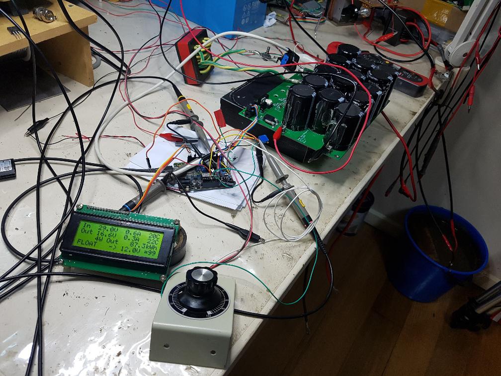 You can see The Blue Bucket Of Resistance, the Arduino Uno and DSO probes and everything. A close up of the Uno. Note that the Nano offers even more inputs useful for this project and that is why I use the Nano for the final brainboard. I just happen to have a Uno lying around.. 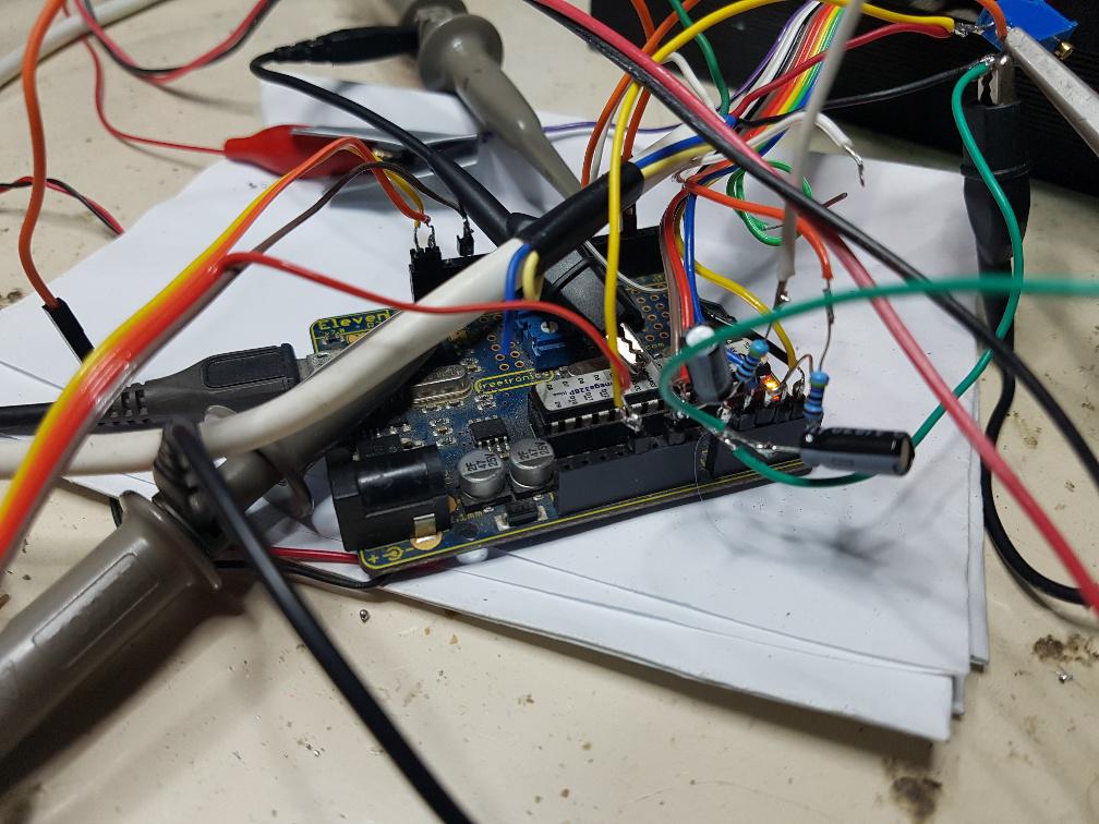 Don't knock it. If it works (and it works really well) then no problem-emo right? Things are looking good for the project. I think this will fly well. wronger than a phone book full of wrong phone numbers |
||||
Revlac Guru Joined: 31/12/2016 Location: AustraliaPosts: 961 |
That looks great, will be perfect for the FLA setup in the shed. Now, changing voltage set points will be easy enough and the comments will tell us which ones. For my lithium battery bank, currently I run 53.5v bulk and 53.3 float because the chargers are designed to use those modes, I can live with that, would it be possible to switch straight to float for this situation? It may go to float faster on a setup along side the existing chargers depending on the set points of each controller, will find out when they work together anyway. Also the last 2 nano's I have needed the Old Boot Loader because of the looping reset or something, there is another bunch that should arrive in 2 weeks, will see how they go. Nice work once again.  Cheers Aaron Off The Grid |
||||
| poida Guru Joined: 02/02/2017 Location: AustraliaPosts: 1387 |
I will probably never use float, so I will put a large ABSORB time in place. And just set the ABSORB voltage as the final bv I want to maintain. Just because there is FLOAT does not mean we have to use it. There are 2 types of Nanos. One type uses the Old bootloader. The other type uses the default bootloader. The only way to find out which one to use is to try one setting and if it fails use the other. Edited 2020-05-24 20:34 by poida wronger than a phone book full of wrong phone numbers |
||||
| poida Guru Joined: 02/02/2017 Location: AustraliaPosts: 1387 |
here is the firmware I am running now. There will be further changes and fixes to bugs and errors and omissions. It is not ready for production. This file is password protected so PM me for the password. v2.zip Edited 2020-05-25 10:40 by poida wronger than a phone book full of wrong phone numbers |
||||
| ryanm Senior Member Joined: 25/09/2015 Location: AustraliaPosts: 191 |
Got a new Rigol on route from out of country. Hopefully should turn up around the same time as the boards. Looking forward to it! |
||||
| SYM-1 Newbie Joined: 18/10/2019 Location: New ZealandPosts: 40 |
I am a firm believer in roll your own solutions. I am a bit of a latecomer to thus thread but I would like 2 sets of boards if there are still any spares available. Grant Persistence is the key |
||||
| poida Guru Joined: 02/02/2017 Location: AustraliaPosts: 1387 |
Hi Grant Kia ora I think there is 2 sets of boards remaining so they must be yours. wronger than a phone book full of wrong phone numbers |
||||
| poida Guru Joined: 02/02/2017 Location: AustraliaPosts: 1387 |
Today was a bit up and down. I hooked up a board running the latest code to the East facing array and then drove the resistive load. I wanted to see how the MPPT would work with a real solar panel array. It found the peak easily and every minute had another look to find the peak. This is as it should be. here is a video of the mppt scan with a solar panel array. Max. power at that time was about 800W. You can see it scan all the way from pwm = very small to max pwm and the inductor current (or power if you like) goes from low to high and back to low. I left the DSO display persistance on so we can see the range of values obtained during the scan. the video I have broken the two nice LEM current sensors with careless change over of boards while one board was still supplied with large input voltage. (we won't go into exactly how "large". That will lead to some embarrassment) Anyway, now I am using the VAC T60404-N4646-X662 15A (but actually +/- 51A) current sensors I pulled out of an Aerosharp a while ago. They of course work perfectly. I was changing things over so that I could feed a board with 100+ Volts. One board uses HY5110 MOSFETS and they are only good for 100V. I wanted to use the one that has 150V. Why? I have a current sensor on the inductor now that can go up to 122A before it clips the output. Before in an earlier post I showed the 49uH 1mm gapped inductor clearly saturated at high outputs with 100V input voltage. Here is exactly how high the current gets. Vin = 108V Pout = 2000W 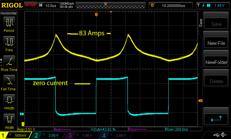 This is not as bad as I thought. Peak current is about 83 Amps and this current is switched by the 2 MOSFETS. I think we are in safe operating area for the MOSFETS, at least as far as peak current. wronger than a phone book full of wrong phone numbers |
||||
| nickskethisniks Guru Joined: 17/10/2017 Location: BelgiumPosts: 409 |
Hi Peter I've sent you a message for asking the password.  |
||||
wiretronics Newbie Joined: 26/04/2020 Location: NigeriaPosts: 5 |
Hi Peter, i've been following this topic as its progressing. Though I was working on a similar project before i joined, all thanks to everyone who has contributed to this. I've done some pcb on proteus. 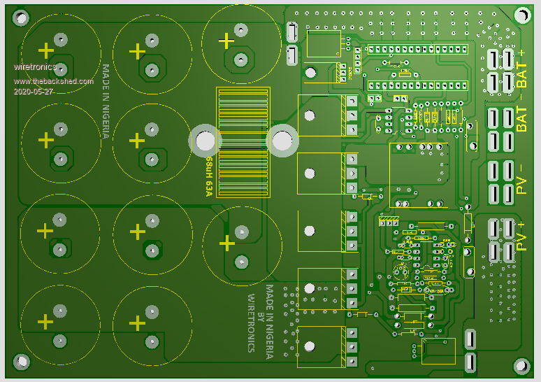 I added an smps that can handle 120vdc without frying the chips. Edited 2020-05-27 10:01 by wiretronics |
||||
| SYM-1 Newbie Joined: 18/10/2019 Location: New ZealandPosts: 40 |
Just let me know the cost and shipping cost. I am keen to try these out charging some lifepo4 batteries. I have a 48V pack and an 80V pack. I guess this might mean some playing around with software or maybe just setpoints. Persistence is the key |
||||
renewableMark Guru Joined: 09/12/2017 Location: AustraliaPosts: 1678 |
Just a heads up for people wanting to order chokes. This one is in stock. It has a 1mm gap, so when 2 are put together it gives a 2mm gap (might be too high.... dunno)?? God knows how they didn't come broken, the packing was terrible and these things are really brittle..... I'm buying a tatts ticket tonight. The 0.1mm, 0.2mm and 0.5mm are all discontinued. IF you have the other type (yes, it's great to have lots of spares) like here they do match up nicely size wise, so you can use one of each to get a 1mm gap. I also recovered some with a total of 4mm gap from some delta GTI's, they appear to be the same size. So ransack the gti's you come across, some have good bits inside. 2 sets of the 8850's might be a good option if enough wire will fit. BTW has anyone got one of these testers are they as precise as a railway nail? Edited 2020-05-28 16:56 by renewableMark Cheers Caveman Mark Off grid eastern Melb |
||||
| shallowal Regular Member Joined: 26/07/2018 Location: AustraliaPosts: 58 |
I've got an earlier version of one of these: https://www.ebay.com.au/itm/Mega328-LCR-T4-12846-LCD-Digital-Component-Tester-ESR-Meter-MOS-PNP-NPN-/322236608053?_trksid=p2385738.m4383.l4275.c10 Really great device for checking transistors/FETs/Diodes/Caps/Inductors and those infernal 4 band resistors. Allan  Allan Allan |
||||
| noneyabussiness Guru Joined: 31/07/2017 Location: AustraliaPosts: 506 |
transistor tester I use one of these, portable with battery included. Seems pretty accurate. Even test zener diodes.. I think it works !! |
||||
| Warpspeed Guru Joined: 09/08/2007 Location: AustraliaPosts: 4406 |
+2 I have one of those as well, highly recommended. Cheers, �Tony. |
||||
| renewableMark Guru Joined: 09/12/2017 Location: AustraliaPosts: 1678 |
I have one of those, I thought it was so crap it never crossed my mind to try and get a reliable result from doing an inductance test. Can't remember what it was, but some tests showed completely different parts to what was tested. Anyway never mind..... sorry getting this off topic again. Poida, can we have a parts list, so ordering can be done. I know you want to test the inductors, but the rest of the values is sorted yeah? Cheers Caveman Mark Off grid eastern Melb |
||||
| poida Guru Joined: 02/02/2017 Location: AustraliaPosts: 1387 |
Mark: Here is the parts list. It may be incomplete, have errors and omissions so I would expect some changes to be made to this. Mike, maybe you could check this? 45A parts.xls.zip wronger than a phone book full of wrong phone numbers |
||||
| Solar Mike Guru Joined: 08/02/2015 Location: New ZealandPosts: 1122 |
You could always use these Powdered Iron Core for your chokes, use 2 stacked with 15 Turns. Cheers Mike |
||||
| poida Guru Joined: 02/02/2017 Location: AustraliaPosts: 1387 |
I have 2 pairs of RS part no. 647-9367 coming (they say "dispatched" but we know better) The come with NO gaps. I have a diamond 4" cutting disc for the angle grinder. I figure slowly and think of Increased Saturation Current and it might just work. Only need one inner core to be cut down about 1mm and leave the other alone. Two of these core pairs with about 8 or 9 turns might do it. wronger than a phone book full of wrong phone numbers |
||||
| renewableMark Guru Joined: 09/12/2017 Location: AustraliaPosts: 1678 |
Just gap them with some ice cream container. You'll never get a consistent gap grinding it. Gapping the entire surface is fine yeah?? At least doing it with plastic will be even and repeatable, grinding will never be consistent. Edited 2020-05-30 18:23 by renewableMark Cheers Caveman Mark Off grid eastern Melb |
||||
