
|
|
Forum Index : Electronics : 150V 45A MPPT - roll your own
| Author | Message | ||||
| noneyabussiness Guru Joined: 31/07/2017 Location: AustraliaPosts: 506 |
pics of test bed... 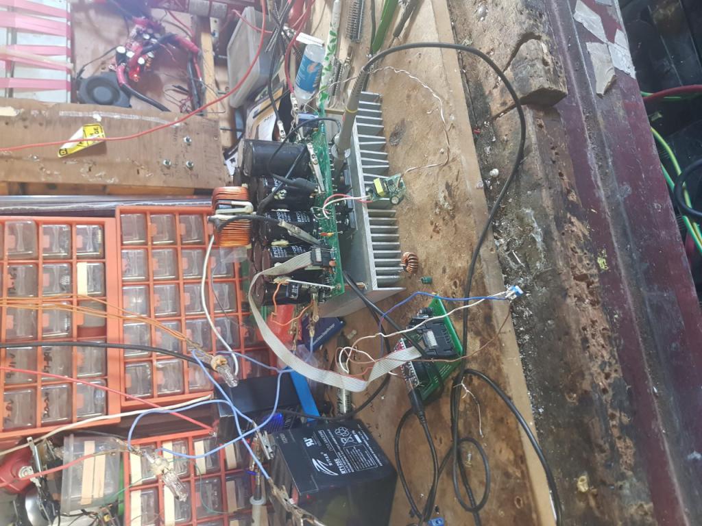 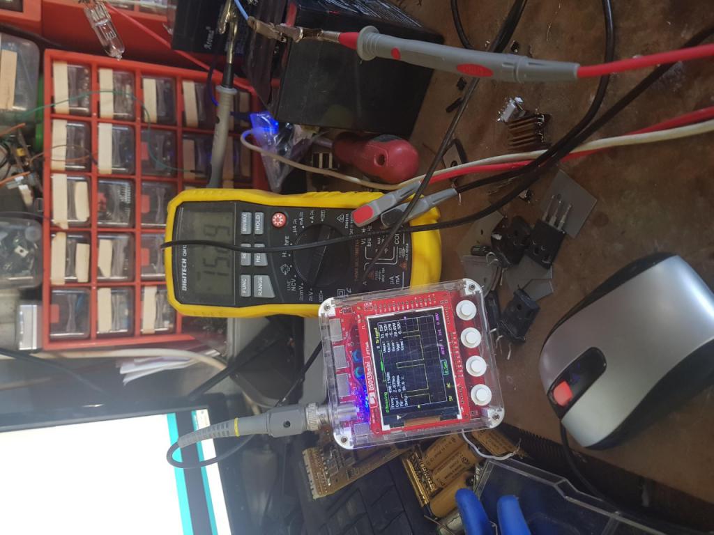 again, thx in advance I think it works !! |
||||
| wiseguy Guru Joined: 21/06/2018 Location: AustraliaPosts: 990 |
Noneya, software is not my forte but at first glance the output volts D - should that be 0.133 instead of 0.0133 - I am using the 54V & corresponding value in the line above as a reference ? I havent looked at a schematic either, just shooting from the hip. if its something I did wrong on the PCB I also apologise in advance ! If at first you dont succeed, I suggest you avoid sky diving.... Cheers Mike |
||||
| poida Guru Joined: 02/02/2017 Location: AustraliaPosts: 1387 |
Noneya: First, it's important that you have made a few changes to the design. This is probably going to be OK but I'll bet something will be overlooked that will be seen as important later. The 10 pin connector appears to be correct, the vital connections that MUST be CORRECT are the two ground pins, 12V and PWM. All the rest are going to analog inputs, 6 in total and we can change things in software to suit. So my first thought is "IS the 10 pin connector correct?" We can prove that with the oscilloscope showing pwm output from the brainboard and the gate drive, relative to ground as it goes into the TLP-250 inputs. Prove this first. Now we need to look at the inputs to the nano on the brainboard. Make sure the midpoint of the input voltage divider goes to "A0 -Vin" 1K resistor. Use the continuity function on the DMM Then prove the output voltage (as divided, on the power board) is going to "A2 - Vout" Then we look at the current sensor outputs. IN turn prove the input current sense output, AFTER R13 on the the powerboard, is going to the 1K resistor "A1 - Iin" and then prove the output current sense is correctly connected. We must be sure that the 4 analog inputs are what we think they are. Then use the DMM and see what voltage the 2 current sensors are putting out. If you used bipolar type sensors, you should see about 2.5V on the output at the sensor pin for zero current. Measure this and all things with respect to battery DC ground Then if all the above is in place my firmware will have a chance of running. wronger than a phone book full of wrong phone numbers |
||||
| poida Guru Joined: 02/02/2017 Location: AustraliaPosts: 1387 |
Noneya: I had a look at your "basic pwm" I prefer not to go there. I would use the code I posted before. I will post it again here. We need to alter things within the code to make the 4 important quantities be correct. This is easy. Connect a 10K pot with Ground and 5V on the outer terminals and the wiper going to A5 on the brainboard. This will be a good test rig for the powerboard. We will be able to see how all 4 values relate to reality. You use the test code in two stages. First is calibration. Apply known voltages to the input, see the LCD or serial console, adjust the code to suit to have it show the measured voltage. Again do this for output. Then apply a known current through the Input sensor, noting that they reflect the direction of flow. Have the positive on the input side of the sensor. Adjust the code to suit. I first set the zero offsets, then I set the gains. Once all 4 are showing correct values, then we hook up an inductor and load and give it a current limited input. Fiddle the pot, see the output change. It will be slow to change after the pot moves. This test program has been of uncountable value to me in developing an understanding of the mppt charge controller. I have many versions of this test code, all tailored for specific power boards and brainbaords. I built 3 power boards, all with different current sensors, and different input voltage dividers. So I have many versions of the test code. Here is a version I know works buck_converter_nics_1_b2_nano_sserial_bb.zip The bits you change when calibrating are: xVin = 0.1196; xVout = 0.0900; xIin = 0.121; xIout = 0.117; tIin = 0.00; tIout = 0.00; oIin = 511; oIout = 512; xVin = the factor to convert input voltage (pin A0) to volts. xVout the same, for output voltage on pin A2 tIin and tIout are offsets in calculations and can be ignored and leave them at zero. oIin needs to be set by you, so that the displayed input current = 0 same for OIout. Lots of builds will need different values. My sensors output about 2.5V and this corresponds to 511 or 512 counts xIin is the factor needed to show the applied current on the input And the same for xIout xIin is connected to pin A1 xIout is connected to pin A3 You can set these easily to suit your build. for instance, using the above values, you apply 30V on the input. You see the LCD or serial monitor show 25V. What to do.. multiply xVin x 30.0/25.0 so that means xVin needs to be 0.1196 x 30.0 / 25.0 or make xVin = 0.1435. Then upload the now changed firmware and check the results on the LCD. wronger than a phone book full of wrong phone numbers |
||||
| noneyabussiness Guru Joined: 31/07/2017 Location: AustraliaPosts: 506 |
thank you for your advice, i have checked it over vs the schematic, but ill go over it again with a fine tooth comb in the morning.. i did try your test code, the only change was the voltage on the serial console when I twiddled the pot, hence why i used that generic code off of google (pedestrian i know)... I've obviously made a boob of myself , i mean boo boo.. I think it works !! |
||||
| poida Guru Joined: 02/02/2017 Location: AustraliaPosts: 1387 |
Under the heading of "pics or it didn't happen" here is the low power mppt controller that is hooked up to the East facing array on the roof. It has run without any issue for a week (I fixed what I think is the last bug in the firmware last weekend) Today we had low cloud and near continuous drizzle. This must be Melbourne! Yes indeed. 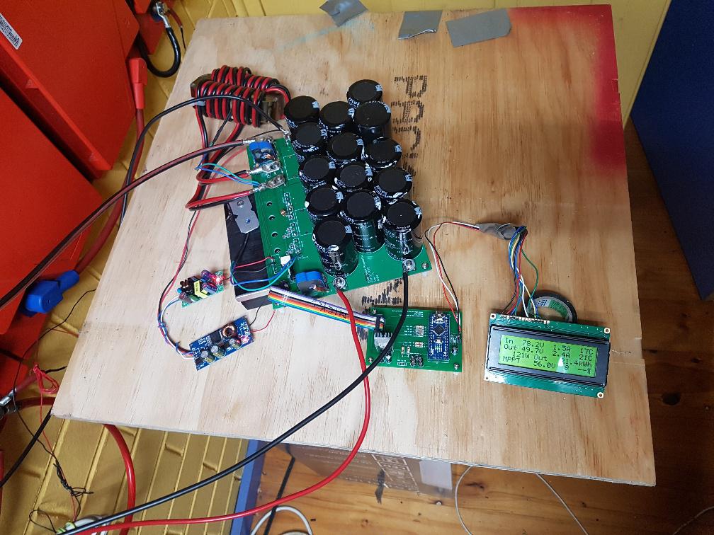 You can see 2 supplies. One is a a non-isolated dc-dc converter, this provides the 12V. The other is a floating output supply which is used for the gate drive of the MOSFETs And for those who say "yeah but I don't have one of them fancy digital oscilloscope thingies so how will I see anything?" My standard test of 20kHz, 110V, 2kW Here it is using the Tek 2235 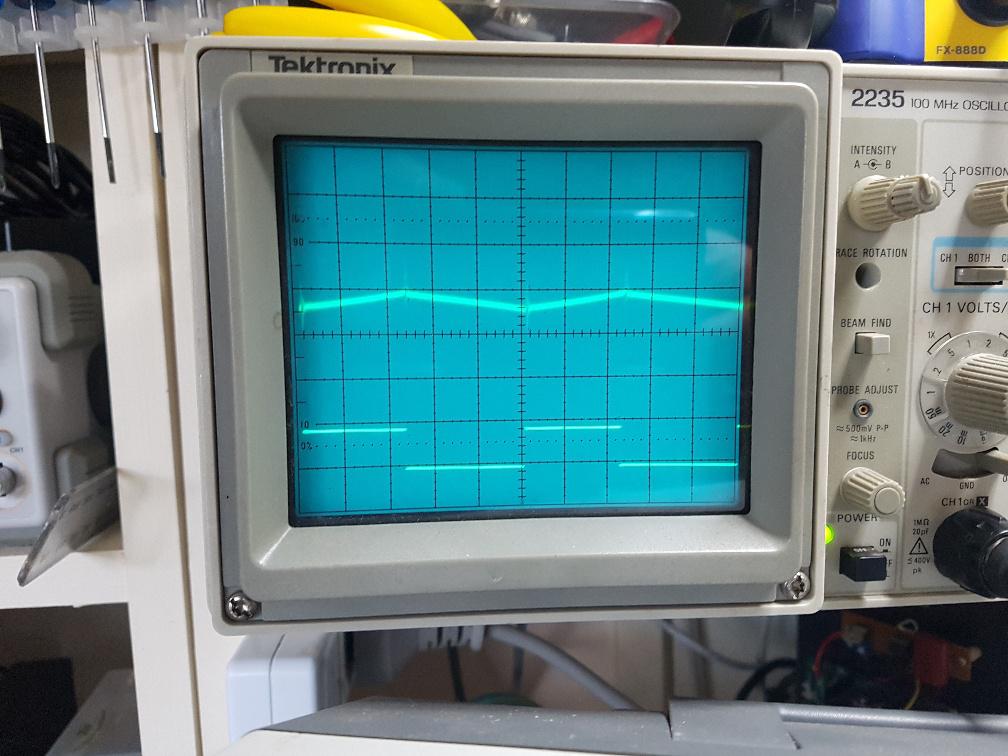 Let's build a few and see what they do. wronger than a phone book full of wrong phone numbers |
||||
| Warpspeed Guru Joined: 09/08/2007 Location: AustraliaPosts: 4406 |
Oh yes ! Looking really good there Peter  Cheers, ĀTony. |
||||
disco4now Guru Joined: 18/12/2014 Location: AustraliaPosts: 843 |
Is a 10K trimpot about the right value here? Could not see it anywhere when I read through. Also I have managed to get my hands on a 3K Aero-Sharp, so will the LEM sensor out of this be OK for the over current. Regards Gerry Latest F4 Latest H7 |
||||
| poida Guru Joined: 02/02/2017 Location: AustraliaPosts: 1387 |
I think a 10K trimpot would be fine. The sensors from a 3kW include the "15" nominal type. These go up to 50Amps. If you want a bit of headroom in the range, shunt the sensor's current sense wires with a bit of 4.5mm2 copper or something. If I recall, you should find 2 "15" types, good for +/50 Amps and one "6" type, good for +/20 Amps And the short circuit protection is not very good. I've blown a board when testing it. It offers some protection, and maybe that's better than nothing. But if also gives a false sense of security. My approach is Just Don't Short Circuit anything. Not input, not output, not inductor terminals. wronger than a phone book full of wrong phone numbers |
||||
| Warpspeed Guru Joined: 09/08/2007 Location: AustraliaPosts: 4406 |
You could perhaps try a low cost 50A fast blow automotive fuse ?  That may arc continuously if there is significant series inductance or at higher dc voltages. But with a bit of thought about where the fuse is located, it might offer some short circuit protection. Best chance might be after the final filter electrolytics. The stored energy is going to vaporize that fuse instantly before the current in the choke can begin to rise high enough to kill the mosfet. Cheers, ĀTony. |
||||
| poida Guru Joined: 02/02/2017 Location: AustraliaPosts: 1387 |
Yes Warp, I simple fuse will help. It would teach me not to do that thing that blows the fuse all the time! I have been thinking about other disaster scenarios. One is when the MOSFETS fail. They usually fail SHORT and so that will have the solar array connected to the battery, via the inductor. The battery voltage shall rise until night time or the human sees the fault. And then next day the voltage of the battery will rise well past damage point. I think I would like the fuse above, on the output. And have an SCR crowbar, with the gate set to about 60V, ready to blow the fuse. During the testing that I am doing with an underpowered solar array source, there is little chance a shorted/failed mppt converter would result in overcharged battery in my situation. It is Winter in Melbourne after all. Summer is another thing altogether. I think I sample the battery voltage, divide it down to trigger the SCR at 60V. And use an RC low pass filter on it to remove any weird spikes that may be present. This is something I would want on any future revision on the power board. I could make it ghetto style all wrapped up in shrink tubing, hanging off the battery terminals of the power board. For added convenience a socket for the fuse would be good. wronger than a phone book full of wrong phone numbers |
||||
| Warpspeed Guru Joined: 09/08/2007 Location: AustraliaPosts: 4406 |
A hardware over voltage crowbar would be the safest way to do it, I have used Motorola MC3425 with success in the past for similar tasks. I have tried simpler circuits, but these can result in false tripping from noise and at power up which can be a damned nuisance. https://datasheetspdf.com/pdf-file/500608/Motorola/MC3425/1 My own system uses a digital battery voltmeter that has under voltage and over voltage alarms, and the respective relay contact outputs activate a shunt trip coil on my battery circuit breaker/isolator. Battery protection does not need to be all that fast, under voltage and over voltage are things that creep up on you. Just a commercial voltmeter module, a shunt trip coil and a few wires makes for something very simple and reliable. Edited 2020-07-07 13:10 by Warpspeed Cheers, ĀTony. |
||||
| Murphy's friend Guru Joined: 04/10/2019 Location: AustraliaPosts: 580 |
Poida, just out of curiosity, on your picture the little display shows "17C & 21C" as the last item in the first two lines. what does that indicate? thanks. |
||||
| poida Guru Joined: 02/02/2017 Location: AustraliaPosts: 1387 |
Those two numbers are the temperatures of the heat sink and the inductor The when under any sort of load the inductor will be hotter. wronger than a phone book full of wrong phone numbers |
||||
mason Regular Member Joined: 07/11/2015 Location: CanadaPosts: 86 |
Peter, received the boards today thanks they all look great. now have to wait for all the parts.. I take it you got the coin for them? |
||||
| poida Guru Joined: 02/02/2017 Location: AustraliaPosts: 1387 |
Yes, I got it a few days ago. wronger than a phone book full of wrong phone numbers |
||||
| Solar Mike Guru Joined: 08/02/2015 Location: New ZealandPosts: 1122 |
Located these small low cost powder iron E220-52 Cores on AliExpress Link , that will work ok at 40 amps and 50% duty. ie 100v PV input, 50v out Stack of 2 cores 40 amps: 20 Khz PWM, 23 turns 6awg wire, Ripple current 10 amps, total loss 17w. 40 Khz PWM, 20 turns, Ripple current 5.6 amps, total loss 12.9w I have ordered 5 sets, will use 1 set on my small generic controller 64Khz PWM, @35 amps Cheers Mike |
||||
| SYM-1 Newbie Joined: 18/10/2019 Location: New ZealandPosts: 40 |
I haven't populated the boards yet and I only have 100 turns of 2.3mm dia on the -2 inductor. I am intending to increase this to 4 sets of parallel sets of 100 turns yet to get the resistance down. Losses are still quite high. Some of this is due to my slow gate switches using 2 sets of PC817 in a DCOI arrangement. I used 2 sets because if you one set you get inversion and the micromite I am using to produce the PWM signal defaults to ON if the program stops so I get full voltage across the output. I have been through a few fuses and $3 FET's. I am using a IRFB4115 FET for testing. The diode I am now using is a VS-UFB280FA20 from RS. It is 45ns and 1.1V drop at 120A. Two diodes in the package. So losses probably high due to 3 things -DCOI -losses in windings The DCOI is quite slow on the rise time but the upshot of this is I have no switching noise. I plan to try out the FET's everyone else is using plus one or two other FET's I have once I am happy the circuit is stable. I blew up my first pair of diodes - they were 10A diodes (2 of them) but they blew up at about 11A. The diode I am using now is rated at 175A and 200V. Here are some pictures of progress so far. 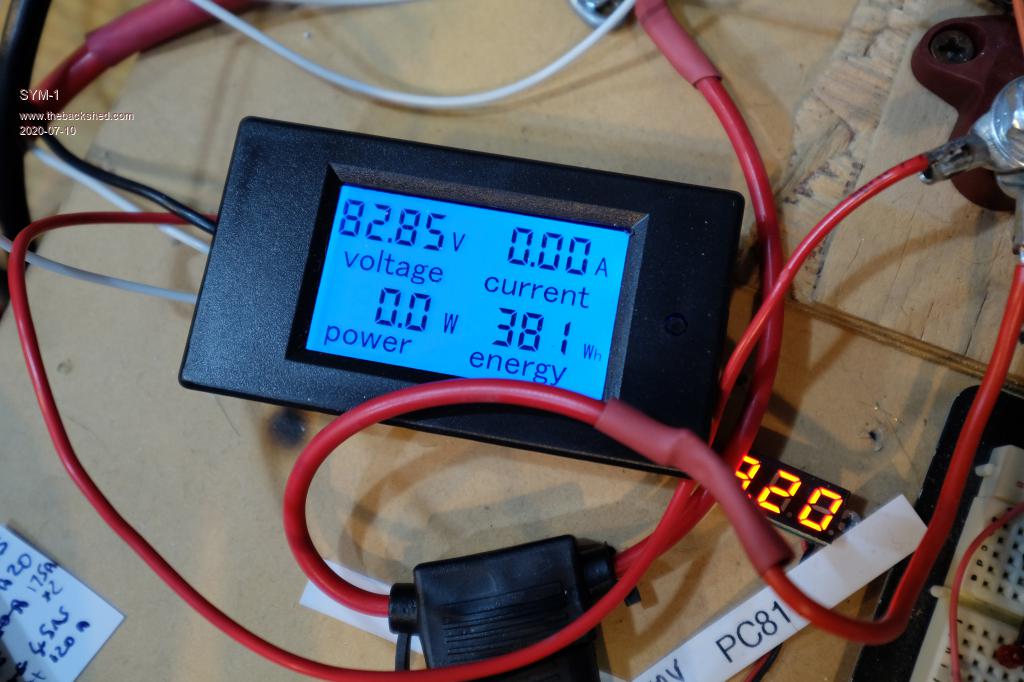 Voltage In Voltage in drops a bit because I have a 1 Ohm resistor to stop inrush at the moment. Here is a picture of the input pulling 1kw from my batteries. 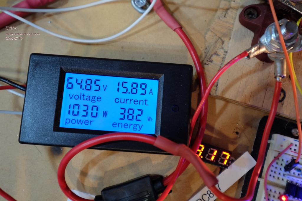 Here is the output 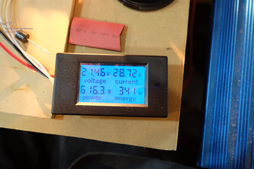 Here is the trace of the output voltage across 0.75 Ohms. I am getting about 5V swing - 6.6A 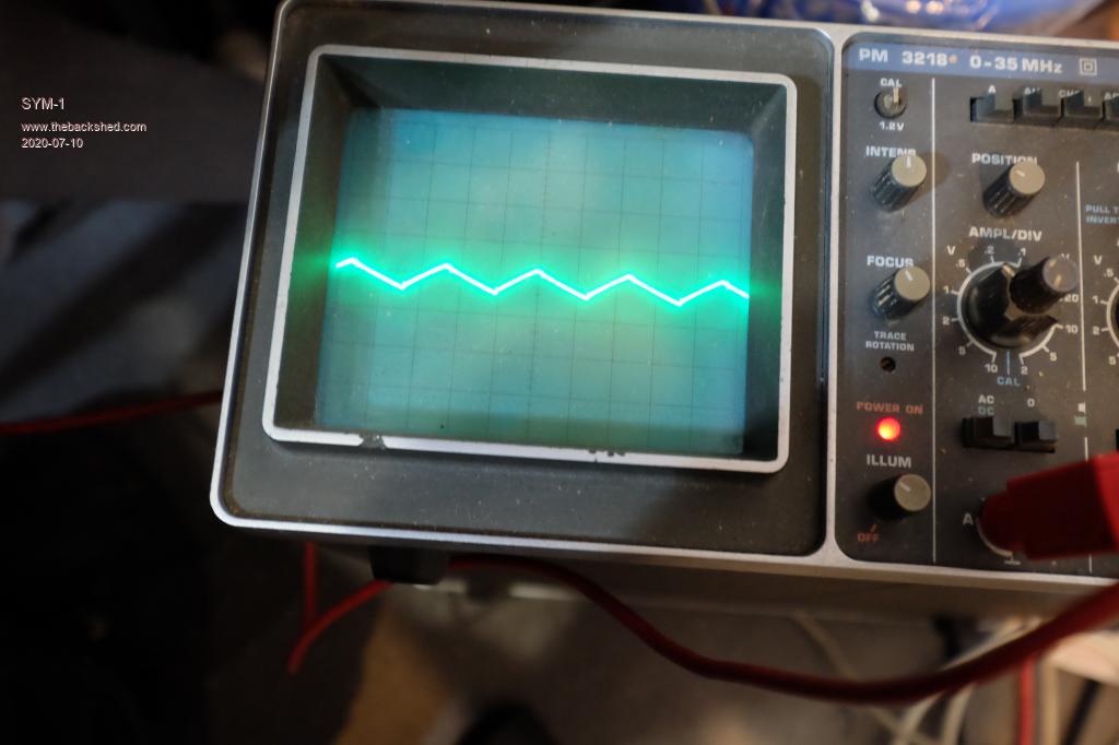 I am running at about 8kHz. At 20kHz I don't get as much transmitted energy. Maybe when I speed up my gate drive I will be able to increase the frequency. I get a bit better efficiency at higher frequencies. Here is a picture of the test bench. The FET is on the big heatsink. It does not get off cold. The lamp is a 24V lamp which is my highest target voltage at this stage and gives me a good idea how the circuit is running. 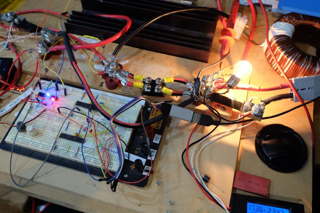 The micromite monitor 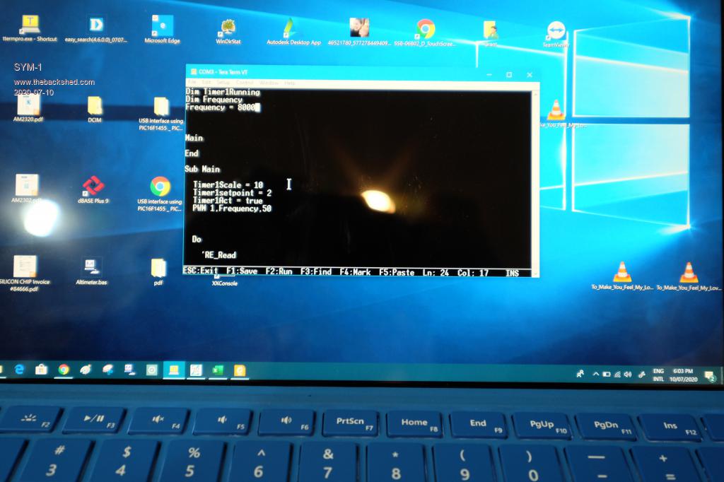 The load 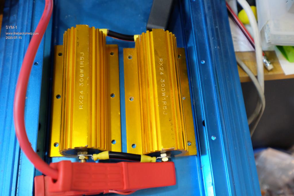 The DCOI driver using PC817's 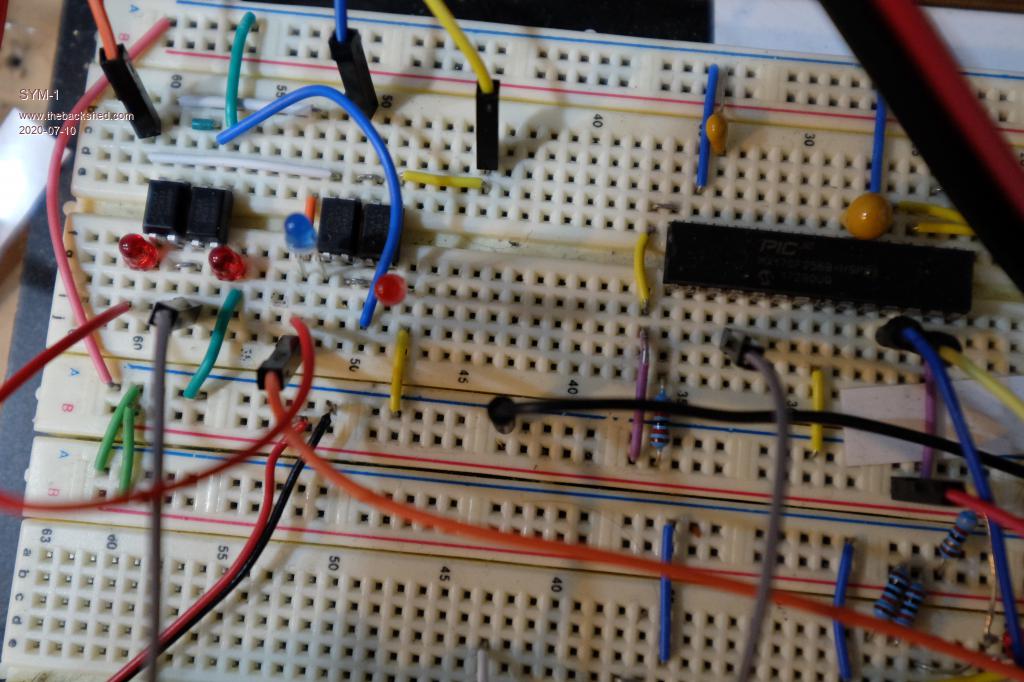 The 5.2 inch -2 inductor with 2.3mm dia windings 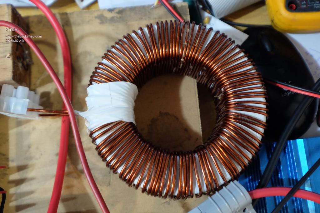 Here is the gate power supply. I think there is some advantage to limiting this 16.9V to 12V to speed up the gate. I will try that in the future. 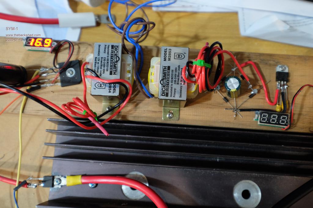 Persistence is the key |
||||
| SYM-1 Newbie Joined: 18/10/2019 Location: New ZealandPosts: 40 |
Here is the swing once the batteries are hooked up - 9A or 18A makes no difference to the voltage trace. When I hooked up a 33000uF 40V capacitor to the output the oscilloscope output was just flat. 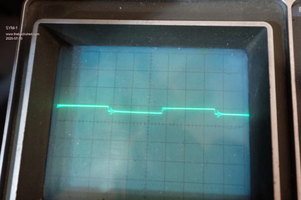 Edited 2020-07-10 17:10 by SYM-1 Persistence is the key |
||||
| wiseguy Guru Joined: 21/06/2018 Location: AustraliaPosts: 990 |
Ok finally found a few minutes to post some pictures of the bobbin I created for the triple stacked EE65 cores. The PCB design as it arrived. 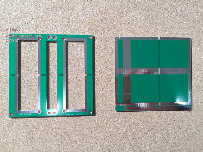 Cut up and assembled (soldered along joints). 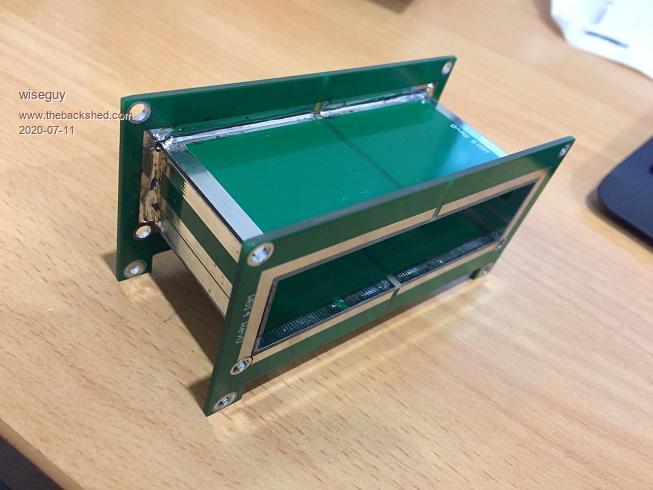 Against a bank note for size reference. 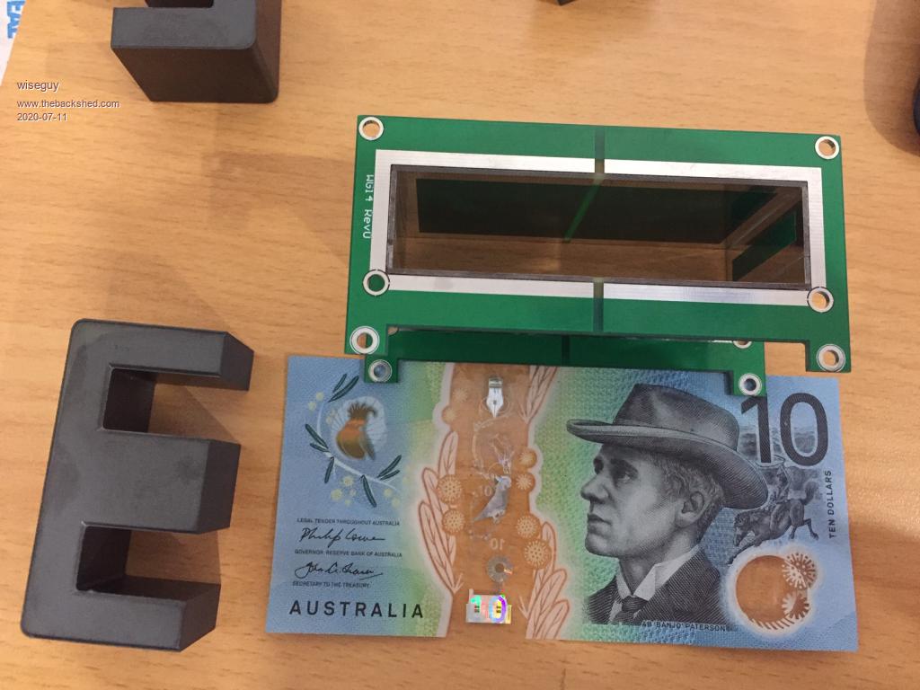 And with 3 x 1/2 cores on 1 side and 1 x 1/2 core other side for a cut away view. 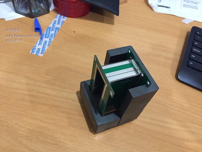 Funny email from PCB maker - Sir we think you have forgotten the drill file - er no there is no drill file. But Sir I dont think we ever made a pcb with no holes. Ok well theres a first time for everything I guess. Please make it as is - there are no holes. The material used is 1mm for the inner bobbin webbing, the two side pieces are 1.6mm thickness. ĀCost for each prototype order (10 pieces each) 2 x $7. I ordered it with another job so freight was free. Each bobbin cost to me $1.40 in pcb material. The finished assembly is seriously rigid/strong, I reckon I could stand on it without breaking it. I will need to file the sharp edges at the 90 degree bends though as they would cut into the wire. The astute will notice a gap in the copper along the centre of the bobbin - this was to avoid a shorted turn. Hopefully I can get some turns on it and have a play with the saturation tester soon. My FETs should arrive next week so I can finally build up a whole unit. If it works as expected and anyone wants one, they can be flat packed ikea style and posted in an envelope for ~ $1.10 no alan key required ! Edited 2020-07-11 19:14 by wiseguy If at first you dont succeed, I suggest you avoid sky diving.... Cheers Mike |
||||
