
|
|
Forum Index : Electronics : 150V 45A MPPT - roll your own
| Author | Message | ||||
| SYM-1 Newbie Joined: 18/10/2019 Location: New ZealandPosts: 40 |
I am having another look at my layout of my test rig as suggested. If you will excuse the combo *circuit diagram - layout diagram* this is what I have come up with. I am using a bit of copper bar to link the FET's with the diode and a bit of copper bar to link the diode with the shunts. This is more a thought experiment at the moment but I am getting some copper bar. What are the implications for stray inductance? Any suggestions for improvement? Yes I do intend to use the powerboard and the brainboard (that are waiting patiently for me on my workbench) but I want to take this opportunity to understand the circuit and try out different inductor possibilities. 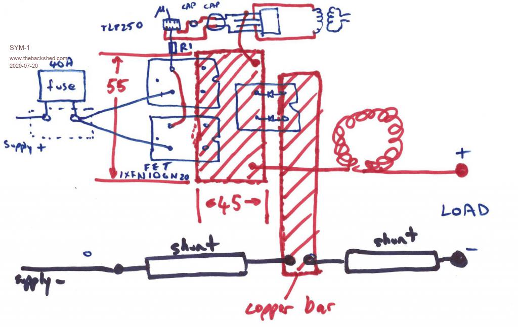 Persistence is the key |
||||
| Warpspeed Guru Joined: 09/08/2007 Location: AustraliaPosts: 4406 |
This also requires a pretty decent capacitor directly across the dc input. The output of a buck regulator is essentially steady dc plus a slight ripple component. The input will be pulsing very violently on and off at the full dc output current. The solar panels need a constant steady load current, so a big electrolytic is a vital part of the circuit. Cheers, ĀTony. |
||||
| SYM-1 Newbie Joined: 18/10/2019 Location: New ZealandPosts: 40 |
Thanks for that. I am testing with a LifePO4 battery bank as my source but I will add a capacitor. Persistence is the key |
||||
| wiseguy Guru Joined: 21/06/2018 Location: AustraliaPosts: 993 |
My advice for paralleling those Mosfets would be to use a separate resistor for each FET gate (main reason is to avoid spurious oscillations) I have had issues with Ixys FETs in the past. Suggest gate resistor values to start with ~ 4.7R. Not sure whether you have a CRO or not, any oscillations at around the + going transition of the gate drive can usually be fixed with one small ferrite bead slipped over one side of the gate drive resistors. Otherwise circuit implementation (with Warps added capacitors at input) (and a cap close to output wont go astray either) looks like a goer to me. If at first you dont succeed, I suggest you avoid sky diving.... Cheers Mike |
||||
| SYM-1 Newbie Joined: 18/10/2019 Location: New ZealandPosts: 40 |
I am a bit worried about the -ve going oscillations in this picture. How about RC networks across the diodes? Any idea of the values? 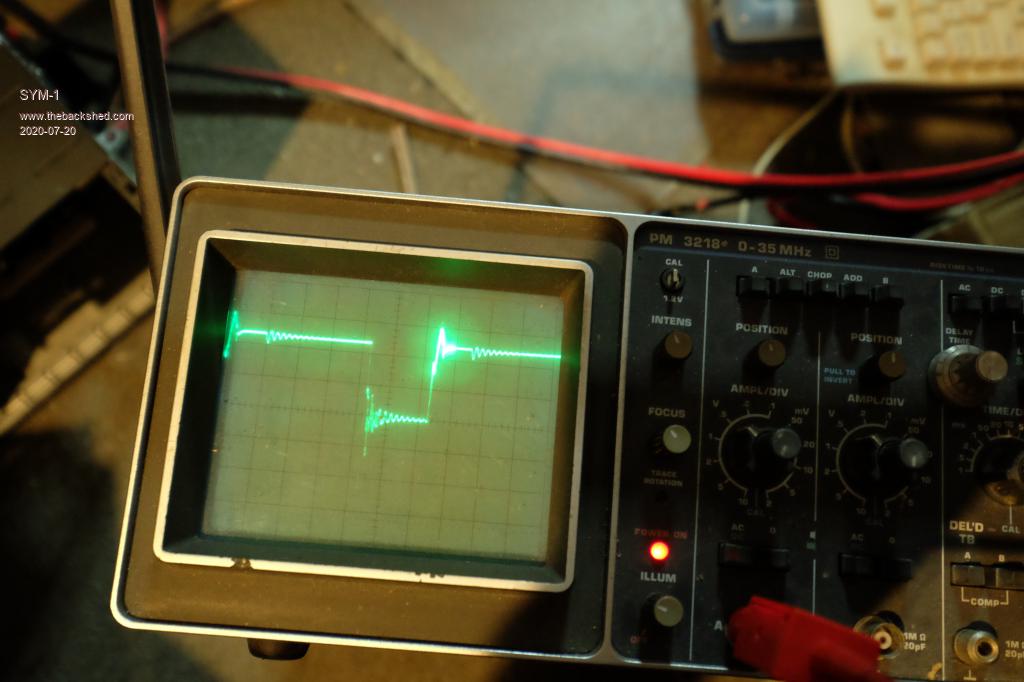 Persistence is the key |
||||
| wiseguy Guru Joined: 21/06/2018 Location: AustraliaPosts: 993 |
That appears to be ringing - a decaying oscillation which is quite normal. The voltages and currents we are working with usually means there is a not insignificant amount of energy in the ringing. ĀRinging is not really harmful usually except the first peak when added to the supply voltage can avalanche the FET causing heat if it exceeds the Max FET Drain voltage. ĀThe ringing can also be exacerbated by not having enough capacitance or and close enough to the input and output nodes. I am guessing the narrow neg peak is during the turn on time of the flywheel diode, a snubber should help to tame it . Typical values to try to snub out the ringing would be capacitors from 470pF to 10nF and resistors from 4R7 to 47R. When snubbed close to optimum, there will be a single peak rise followed by one smaller undershoot that then settles to a constant level. If the resistor gets hot or burns your fingers either the cap is too large or the resistor value should be reduced - looking at the CRO trace whilst carefully placing the temporary snubber values across the diode is a good way. ĀStart with 10R and a 470p capacitor and then vary the values to another increment whilst observing the CRO trace is heading in the right direction. Dont try for a perfect square-wave you will waste way too much energy achieving it. It is also important to follow good probing techniques - Poida described these a few times in some of his posts sometimes the ringing you are looking at is fake (not the Donald Trump type...) and caused by improper probing technique. Edited 2020-07-20 16:32 by wiseguy If at first you dont succeed, I suggest you avoid sky diving.... Cheers Mike |
||||
| poida Guru Joined: 02/02/2017 Location: AustraliaPosts: 1388 |
If I were you I would build both boards. I would use HY5110 MOSFETs as the diodes, not use the FDH055N15A. (The FDH055N15A are very good MOSFETS and I think we are best advised to use them as such.) Or find some large diodes to suit. Any dual TO-247 "fast" switching power supply diodes will do. Keep in mind the board is designed for 45 Amps output so the dual diodes need to be about 30A each at least. If you want to use HY5110, LCSC have them and I used theme before. They are reliable. https://lcsc.com/product-detail/MOSFET_HuaYi-Microelectronics-HY5110W_C128014.html Then after loading the most recent code I posted, you will have a good test setup for evaluating inductors. As far as probing the response of the circuit, I would always want to set up a probe with ground being DC ground and the signal on the inductor/MOSFET SOURCE/DIODE node. And not use long leads. Long leads when looking at sharp square wave signals at about 20kHz can be 4 inches. This is too long. Here is how I probe a powerboard at the above described node. 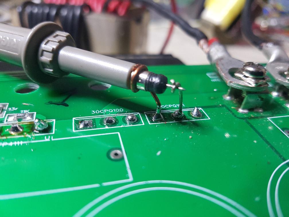 just solder the two wires on pins of the diode. You will find it easy to determine which pins are what. This probe technique gives a high quality signal to the CRO. What you see with this probe tech. is what is on the pin. (for frequencies up to 100MHz and that is all we need to care about anyway) wronger than a phone book full of wrong phone numbers |
||||
| poida Guru Joined: 02/02/2017 Location: AustraliaPosts: 1388 |
I added the current throttling due to heat sink temperature function to the firmware. You need to set it some value that means something to you. For me I have the heat sink maximum temp set to 75C and the new value "HS throttle low" set to 55C on the working prototype connected to the East facing array. This will have the controller reduce the maximum output current gradually, from 45A - the maximum current - at 55C to 0 Amps at 75C If the heat sink goes past 75C, the controller will switch off and show "overcurrent" on the LCD. When current is reduced due to throttling, an "!" will be shown on the LCD in the top right corner, where the heatsink temp is displayed. If throttling is not in effect, then there will be a 'C' instead. The "*" next to the temperature means the fan is switched on. here it is under test conditions with no throttling: 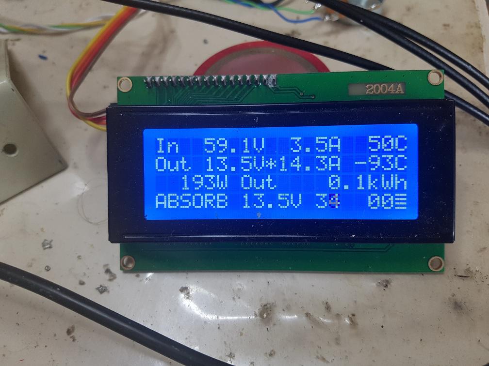 and when throttling is happening. I use different values during the testing (and photos). No NTC is connected to the toroid NCT input so it shows a nonsense value of -93C. 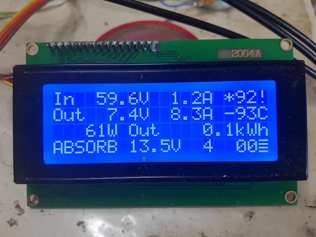 I had heatsink max = 100C and HS throttle low = 80C and a maximum output current of 20 Amps. This means a simple relation of throttled output current. up to 80C = 20A 85C = 15A 90C = 10A 95C = 5A 100C = 0A In the photo above we see HS temp is 92C so the output current limit is now set to 8 Amps. This is what is in effect. I think this will make the controller behave in a way it will not need a fan even if the heatsink is undersized. It will not overheat the MOSFETS. The LCD display is very useful to see what is going on. I probably need to write a book on how to build a controller and run it. Latest code with heatsink temp throttling: EDIT: minor change, put the 2 files into one directory mpptv5.zip The prototype mppt controller running the East facing roof array has now clocked up 54kWhr, averaging about 2 to 3kwHr per day for 3 weeks or so. This is to be expected with my system and is quite similar to that which was done with the Morningstar PWM controller over the past year. Edited 2020-07-22 20:50 by poida wronger than a phone book full of wrong phone numbers |
||||
| nickskethisniks Guru Joined: 17/10/2017 Location: BelgiumPosts: 409 |
Nice progress, I like the throttling back function! At the moment I'm on holiday in Switzerland for some hiking, so I can't do testing. I hope it rains a few days so I can do some research before ordering some extra components.  |
||||
| SYM-1 Newbie Joined: 18/10/2019 Location: New ZealandPosts: 40 |
I am busy at work for the next couple of weeks so I can't work on the MPPT. I really like the throttling. This enables the system to survive and keep working even if an essential fan wears out and stops (which can happen even in a matter of months if you are unlucky). Nice thoughtful design work that all engineers should employ. Persistence is the key |
||||
| Warpspeed Guru Joined: 09/08/2007 Location: AustraliaPosts: 4406 |
If something's very survival depends on a fan, it probably won't live very long. Fans are good for increasing reliability even further on something that is still safe if the fan stops. Throttling is a really nice feature. Cheers, ĀTony. |
||||
| nickskethisniks Guru Joined: 17/10/2017 Location: BelgiumPosts: 409 |
Hi Poida, I noticed you are using the same dcdc as I used in the past, IÆm using 2 in my ozzinverter, 1 for 5V the other for 15V. Last weeks I noticed a hot buck inductor in one of my other prototypes, my ōbattery monitorö that I use for disconnecting my solar panels as last protection when my solar controller would go short circuit. This Āōmoduleö also has 4 other mosfets for switching relays/ contactors, like the 3kw hot water element and the main contactor after my inverter. The board used to send data over wifi to thingspeak so I could monitor the battery over the internet. There are also some other icÆs but that was not my point to make. 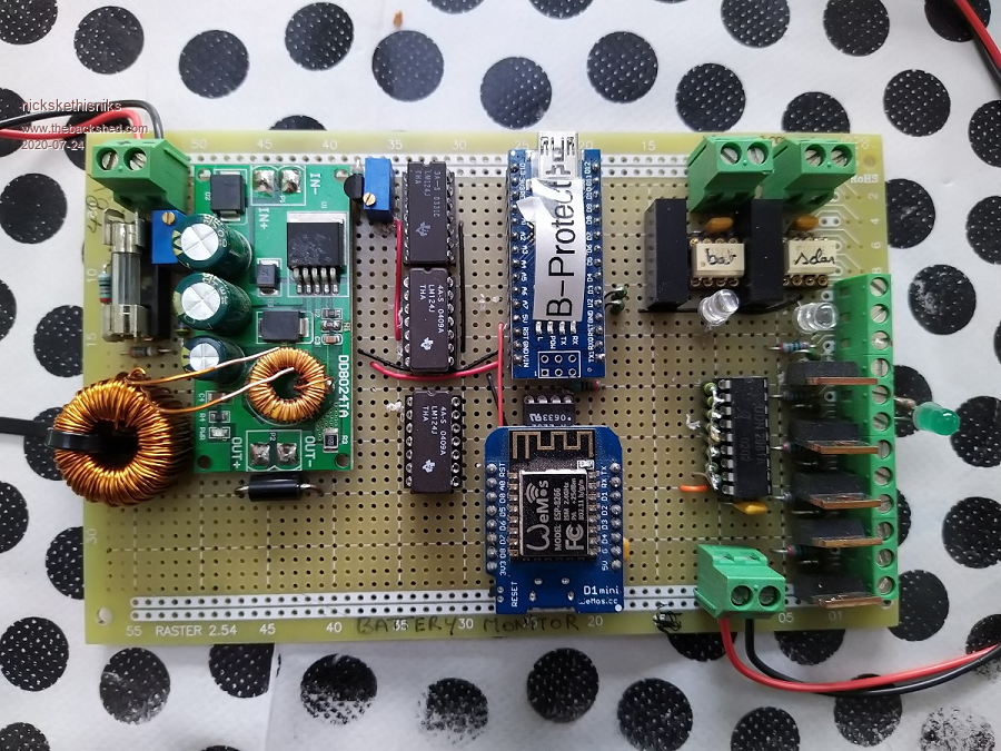 What I wanted to say was that the inductor was running hotter week after week, I decided to change the inductor with a self wound T90-26 core. Probably a little bit over kill, but hey why not spent one hour to make some +200turns for a ōprotectionö system. Ā  I also added a suppressor after the dcdc, if it goes bang it will safe the rest by blowing the glass fuse. I also added a suppressor after the dcdc, if it goes bang it will safe the rest by blowing the glass fuse. I may call it, thermal runaway, if you read the micrometals datasheet, those cores can degrade really fast under the right circumstances (a lot of heat). The original had 100ĄH, it now has 2mH and it runs fine without heating up. I think there is only 50mA power draw on 12V. My other boards are fine, I just wanted to let you know. 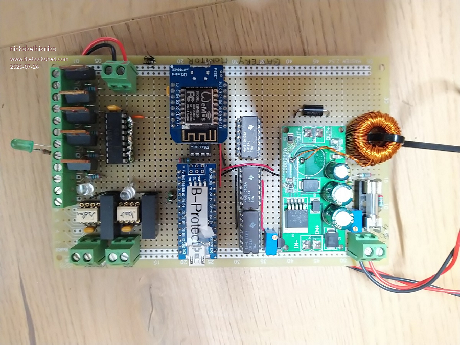 For disconect I use a Schaltbau contactor, they sometimes come on ebay: (don't know wich type from memory) Contactor Edited 2020-07-24 03:56 by nickskethisniks |
||||
| poida Guru Joined: 02/02/2017 Location: AustraliaPosts: 1388 |
I was working on the raspberry pi control/logger system, replacing the entire thing when I needed to isolate battery supply. This then lead to a little bang, fizzle and smoke from the mppt controller I just built and had running for 3 weeks. I was quite proud of it, see above pictures. oh no. what went wrong.. I replaced the board with a spare (I have 3 spare boards now.) and had a look at the broken one. Is there a fatal flaw in the design? Something we all overlooked? Will I need to call out to us all to say the design is flawed? I used a 16V Tantalum cap on the high side of the the 12V regulator. This cap receives 15V and fairly carefully regulated 15V too. This cap failed, went short as Tantalum caps do and brought down the mppt converter. No other problems with the board. This board has had 3 weeks running the East facing roof array that provides about 105V DC open circuit voltage as input. The board uses HY5110 MOSFETS and these are rated at 100V DC maximum Drain to Source. I thought I had fried them but no, it's all OK. I suspect the MOSFETS see only a Drain to Source voltage of (Vin - Vout) so that is about 50V but I could be wrong. See my sig below. Capacitors. You can't live with them and you can't live without them. I tried a bit of a hack with a mppt board that donated all the 470uF caps for the Wiseguy powerboard I built last week. Well, I need more caps for this board that donated it's caps for the new Wiseguy board build and there is a couple of 100V 10,000uF Chinese Electro caps looking for a use here. So I fitted one on the input side, which sees up to 108V DC, and one on the output that sees about 50V. I fired it up and less than than one minute later the input cap popped. So it seems a Chinese 100V 10,000uF cap does not like 108V. Not a lot of tolerence at all. I thought there would be some leeway, some wriggle room but no. Yesterday was the same. A 16V Tantalum 4.7uF SMD cap from Alltronics did not like 15V (and not even 15.5V, it was 15.0V) for 3 weeks. It smoked and went short circuit. I replaced the 4.7uF 16V Tant with a 0.1uF 50V ceramic, since that's about all you need to stabilse a 7812 regulator and I expect no more smoke. wronger than a phone book full of wrong phone numbers |
||||
| poida Guru Joined: 02/02/2017 Location: AustraliaPosts: 1388 |
Nicks: good to read about how you look after problems with dc-dc converters. I see the cheap Chinese converters as a very good starting point. We must feel free to modify them as we need for particular circumstances. They cost so little but bring all the basic requirements to the starting point. I needed 12V but had only a 15V converter. No problem, just put 4 slow 1N4007 diodes in series, give it a 2KR load and now it's a 12V supply for about 0.5A It's sort of like having a few tools in the toolbox. wronger than a phone book full of wrong phone numbers |
||||
| noneyabussiness Guru Joined: 31/07/2017 Location: AustraliaPosts: 506 |
poida, i've had so many issues with Tantalum caps i don't use them with intent.... good old electros if need bulk, else some form of ceramic... im sure they are valuable in certain areas but still hate them with a passion.. I think it works !! |
||||
| Warpspeed Guru Joined: 09/08/2007 Location: AustraliaPosts: 4406 |
I too am now convinced, those low cost dipped tantalums are an instrument of the devil. Some time ago, I bought bulk quantities of various assorted low ESR electrolytics, and now use those everywhere instead of tantalums. So far not a single explosion. Cheers, ĀTony. |
||||
| Solar Mike Guru Joined: 08/02/2015 Location: New ZealandPosts: 1123 |
Tant caps don't like voltage surges, eg applying power to a pcb with tant caps fitted; it is the fast rise time voltages that kill them. They are more suited after 3 term regulator outputs with slow rise times not before, or for low impedance decoupling around op amps etc. Definitely don't use them in mosfet drivers or boot-strapped circuits. I too have had them short out, but they do have their place. 10 - 20uf low voltage ceramics are now quite inexpensive, I tend to use them more often; you cannot beat electro's though for bulk charge storage. Mike |
||||
| poida Guru Joined: 02/02/2017 Location: AustraliaPosts: 1388 |
So, with the spare board that has no caps I put the 2 remaining 470uF 450V on the input and one 100V, 10,000uF on the output. I then give it the berries. Let's see what breaks. I drive it with 87.6V input, 2000W output into the bucket of Ohms which is right now 47.7V and 41.2 Amps. what gets hot and what does not? The two 4&0uF caps get quite warm. Not too hot to grip with the hand. The inductor gets warm too but not beyond the PCV insulation limits. The 10,000uF cap stays cold. The 2 oz PCB track joining the MOSFETs to the inductor gets nice and warm. The heatsink gets nice and warm. Next test is to see how the mppt firmware performs. This is interesting since we have 10,000uF on the output, instead of 5 x 470uF (2,350uF) Will the mppt scan function work at all? For background info, here is how it works. (by the way I have nearly boiled the 10 litre bucket of water that cools the nominal 1 Ohm resistor. I can hear a changed sound from the bubbling.) the mppt scan function ramps the dc-dc converter from 0V output to max in steps. I wait a little for things to settle and measure the output power at each step. This way we can find out what pwm duty width is the biggest power. The delay and waiting for things to settle bit is what will be effected by the change from 2,350uF to 10,000uF. I suspect the board will still be adjusting to the new pwm width before the firmware measures the output power and so we will get incorrect or meaningless results. Testing has shown that it's all good and a reasonably accurate measure of maximum output power is obtained when 10,000uF is on the output filter of the converter board. This means we do not have to be very careful with the capacitors we choose to use in the build of the mppt controller. I suppose we need to be reasonable with it. something like 3,000uF to about 10,000uF is going to be OK. I want to stress that the project needs to be "use what you have lying around" Not spend big $$$ and make it. We all must have accumulated various components over the years and so this project can use some of them. wronger than a phone book full of wrong phone numbers |
||||
Revlac Guru Joined: 31/12/2016 Location: AustraliaPosts: 961 |
Sounds good poida, I have gathered up a set of capacitors from various things, some PSU's give them up easily when threatened decent soldering ion, some 680uf, 820uf and a pair of 1200uf should workout nicely, haven't spent anything on caps yet.  Still waiting on a few parts to arrive. I think this charge controller will give me the opportunity to use one of those odd shaped one off heatsinks. Might put a fan in for summer, my other charge controllers went over 65c and ambient was temp 47c, will see how it turns out. Cheers Aaron Off The Grid |
||||
| poida Guru Joined: 02/02/2017 Location: AustraliaPosts: 1388 |
I thought I better see how the mppt will go with a hot heatsink. After designing a dc-dc converter, I was wondering if it would run OK when hot. But it would take ages to heat up enough when under load. So I had to preheat the heatsink with the 2 x IGBT variable DC load module to about 65C and put the converter to work. Test conditions: 110V in 51V out 2000W out 65C heat sink temperature The mppt board uses 2 x FDH055N15A MOSFETS and 2 x HY5110 as diodes. No problems, stable running from 15C water up to the point where the bucket of resistance starts to boil. Ā check out the video that's insane This gives us some guidance when setting a heatsink upper temperature limit. 2kW is OK at 65C, probably good even to 2.5kW or 50V @ 45A 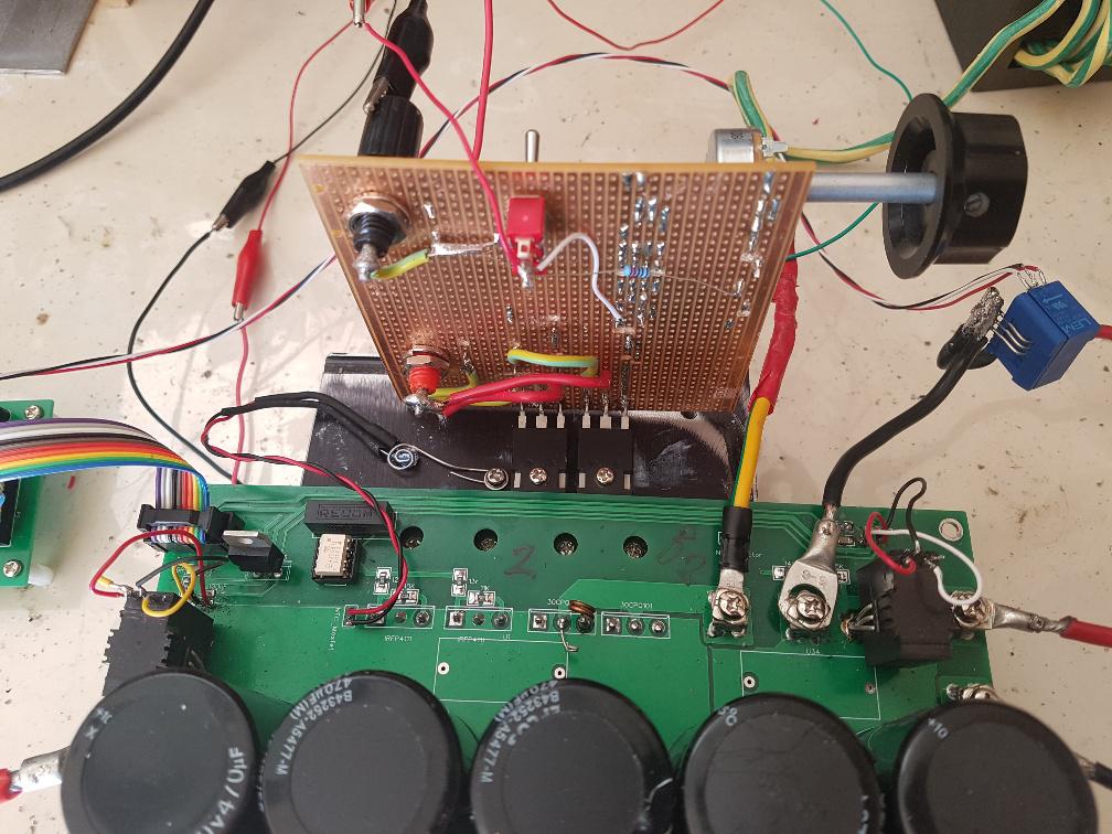 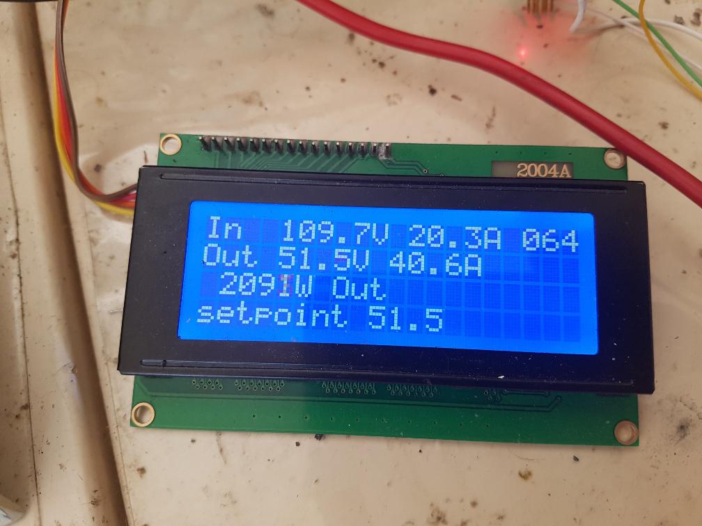 Edit: I just took it to 75C, no problems. Edited 2020-08-10 13:32 by poida wronger than a phone book full of wrong phone numbers |
||||
