Notice. New forum software under development. It's going to miss a few functions and look a bit ugly for a while, but I'm working on it full time now as the old forum was too unstable. Couple days, all good. If you notice any issues, please contact me.
poida Guru Joined: 02/02/2017 Location: AustraliaPosts: 1387
Posted: 11:15pm 22 Oct 2020
Copy link to clipboard
Print this post
400 kW.hr all good.
wronger than a phone book full of wrong phone numbers
poida Guru Joined: 02/02/2017 Location: AustraliaPosts: 1387
Posted: 09:29pm 12 Nov 2020
Copy link to clipboard
Print this post
Still running perfectly. 500kW.hr The only problem which remains unsolved is how to pack all this into an enclosure but keep the size of the box small.
wronger than a phone book full of wrong phone numbers
andymc70 Regular Member Joined: 30/06/2019 Location: AustraliaPosts: 42
Posted: 10:56pm 12 Nov 2020
Copy link to clipboard
Print this post
Hello Peter I would be happy to design something up and print/laser cut it for you to hold it all together. Just let me know if that something you would like to happen. Andy
Revlac Guru Joined: 31/12/2016 Location: AustraliaPosts: 961
Posted: 08:57am 14 Nov 2020
Copy link to clipboard
Print this post
Andy, Would be great to see your case design ideas for this charge controller. I was also thinking of making one, I have done a lot of laser cut ply wood and some perspex, I find the perspex a little hard to get at a good price, using scrap off cuts,
The 3d printed circuit board standoff's could be done with a screw hole buttress on one side and a nut insert on top for the circuit board, push the nut in the top of the PLA printed standoff with a soldering iron and the nut holds in really well.Cheers Aaron Off The Grid
andymc70 Regular Member Joined: 30/06/2019 Location: AustraliaPosts: 42
Posted: 10:01am 14 Nov 2020
Copy link to clipboard
Print this post
If your in Melbourne, AB Plastics in HALLAM has good prices on perspex.
I have used that technique to insert fastners before it is a good technique.
nickskethisniks Guru Joined: 17/10/2017 Location: BelgiumPosts: 409
Posted: 09:19pm 18 Nov 2020
Copy link to clipboard
Print this post
It's been a long time since I had some motivation to work on this (not only this...) project again, I've got one controller and it's really working great. It�s more then a year in service and it�s has seen some serious overcurrent (and +5000kWh!), it was only intended for a third the current it is now handling.
My protocol was just reading the panel voltage, and make sure it stays at 62V all the time, It is a very stable and simple solution. The output was read to fold back the duty cycle to prevent overcharging. But it�s becoming winter and I�m convinced Peter�s tracking software could give me some extra % energy gain.
So today I did a small test on the bench, and since I�m not having the right hardware at this moment, it was all about calibration. I don�t know how much people this controller are using at the moment, but I guess it�s only me and Peter, forgive me if I�m wrong, then I�m heavily underestimating you! I�m going to be honest, even for me it was a little bit frustrating to set everything up. But I think Peter explained it very well in a previous post.
But here are my struggles I hope you can use these thoughts/tips:
So calibration is needed to have good measurements, �for calibration you need laptop/pc. The nano �C is powered by the usb cable and external circuit. So I did the calibration and then when disconnecting my calibration was not good anymore. Somehow the internal voltage reference is influenced, did you have problems Peter or know how to solve this issue? �Don�t really know what is going on here. I will do this again with and without external power to see if there is any difference. The voltage was of by 10%...
--SOLVED!-- for the LM7805 I�m using the switched mode replacements, the problem occurs when I�m only powering the nano with usb during calibration. If you have a strong usb voltage then there will probably no problem. But because I have a weak usb voltage and 2m programming cable, my reference voltage was only 4.6V. The switched regulators wont kick in if there is already some voltage applied on the output. So I needed to power them first and then plug in the usb cable. Then reference voltage is 5,01V. So my advice is to check the reference voltage, make sure it�s �close to 5V. �The electronics, 2 nano�s ( 1 for the serial to lcd conversion) + LCD are asking 90mA 12V in my situation. So not bad.
--HARDWARE:-- Design, you could use several types of mosfetdrivers, for me the most common are TLP250 and FOD3182. I use both and both are fine, I recommend TLP250 for 20khz use and FOD3182 for both 20 an 40khz, the last one can handle higher frequencies. In my first design there was no 10uF capacitor for the mosfetdriver, only 100nF, with the TLP250 this was not a real problem, with the FOD3182 this caused instability problems in the gate drive and gave rubbish in the �C.
Keep the ribbon cable as short as possible, the shorter the less noise it will pick up.
Be careful when using a power supply and oscilloscope and laptop,�. I had grounding problems� An isolation transformer should prevent that, be careful during troubleshooting and taking measurements, you are working on some dangerous voltages. I tried a variety of inductors, and there was one that was producing some noise picked up by my �C.
My display gets upset when I touch it, my display gets upset when I touch my inductor, it could be the long straight wires. That� a problem for later.
Be careful, capacitors charged to 50V or higher can give some nasty large sparks! Guess how I found out :p.
For my first version I had to place the ribbon connector 180� twisted, not a problem. I don�t know how it is with Peters and Wiseguy�s version?
The brainbord is good as it is but I�m going to design a new pcb brainboard with some extra interfaces and maybe supply, but that will take some time and probably for next year.
I hope to implement this brainbord to my main controller this week and see how it behaves, but on my bench I was impressed Peter, I like your code very much!
Thanks Peter! Edited 2020-11-19 07:19 by nickskethisniks
nickskethisniks Guru Joined: 17/10/2017 Location: BelgiumPosts: 409
Posted: 07:42pm 20 Nov 2020
Copy link to clipboard
Print this post
So today I had a little time to test Peter�s brainbord on my main solar controller. Exciting�. :p
Because I took another power pcb, so other component tolerances I had to do the calibration all over again, but I�m trained now. It�s actually going verry smooth now I know all things I need to think about now. Even when full solar and battery were connected I could set all the parameters without things blowing up.
Yesterday I had problems with my LCD screen, very sensitive. But as expected my wires were to long between my lcd and pcf8574, added 100nF to the 5V line on the LCD, and 100nF + 1�F close to the pcf8574, all problems solved.
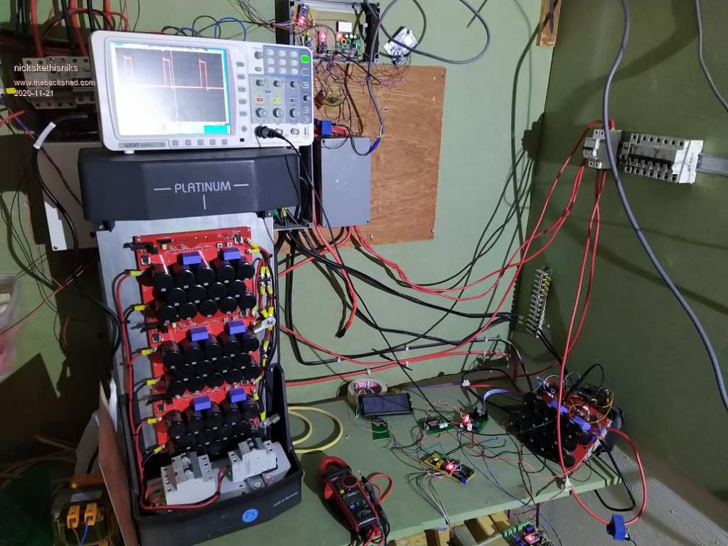
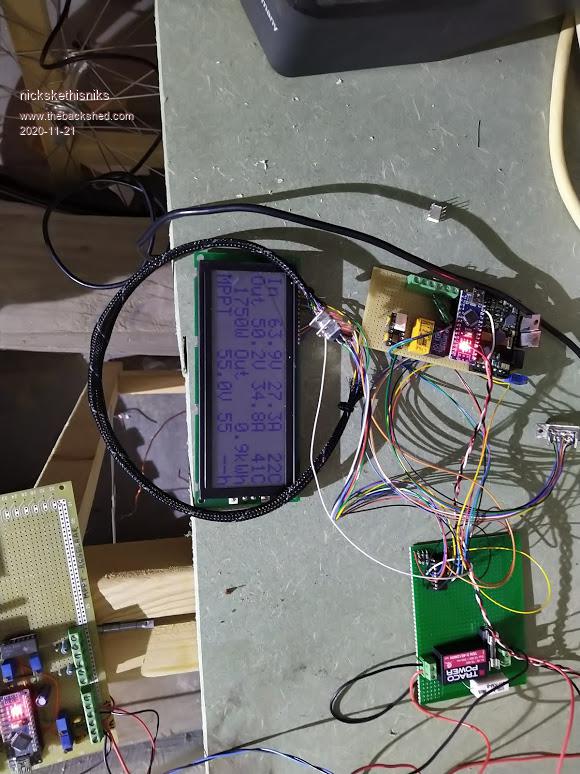
You see a few boards but it's because I reused a board from another project.
This is my testing setup, yes there is some work left to make everything a bit euhh... :p
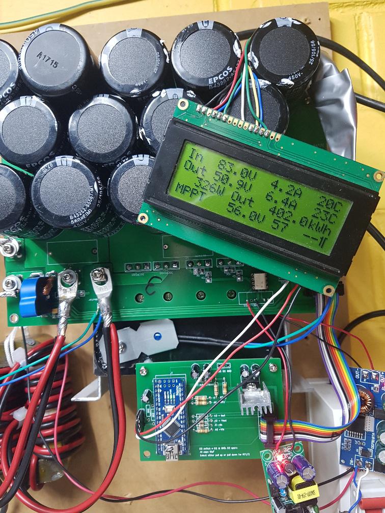
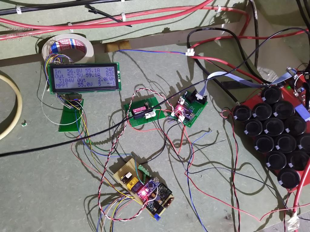
Early morning testing with low battery, here an mppt controller makes a lot of sense, 10A in almost 14A out...
1700W going in the battery:
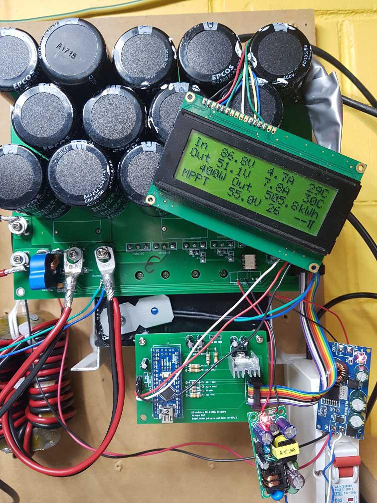
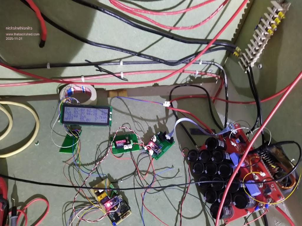
Power keeps climbing, temperature of inductor was climbing under those currents so I switched on the fan. I need to figure this out.
This was about maximum power level for today, that is for a +-6700Wp array.
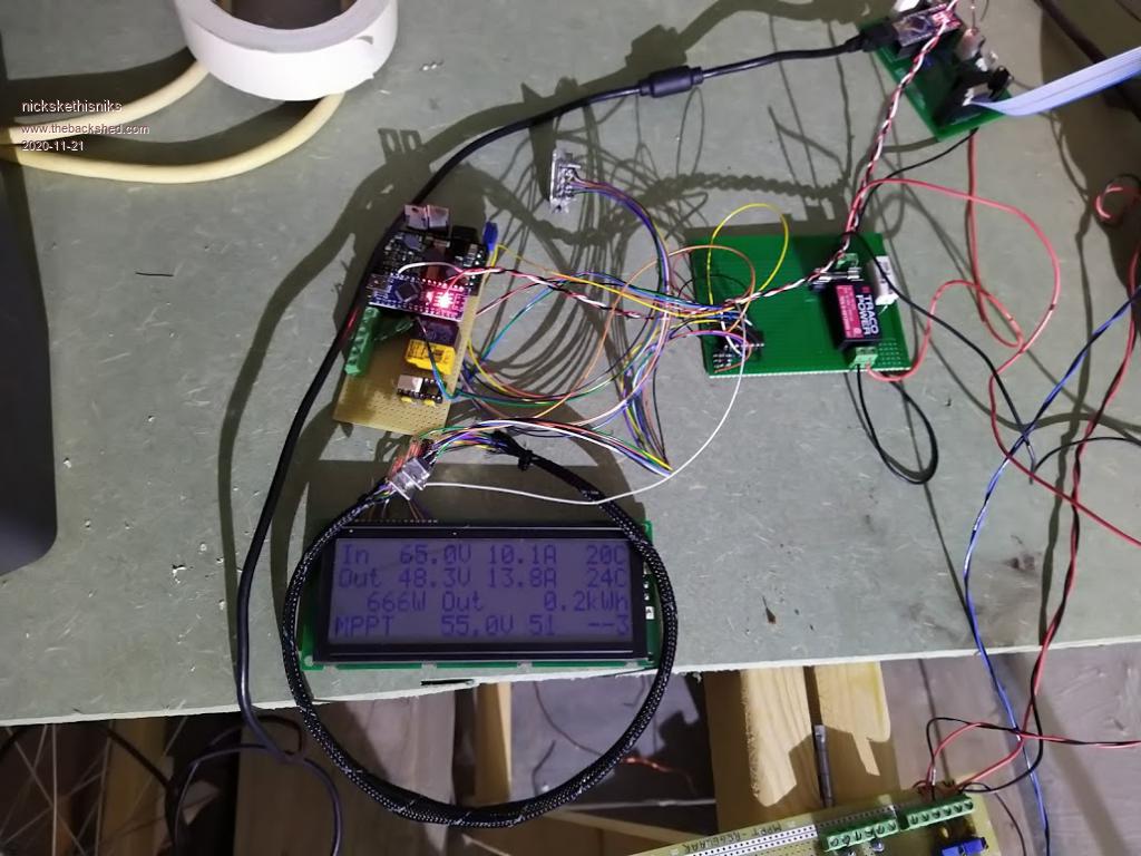
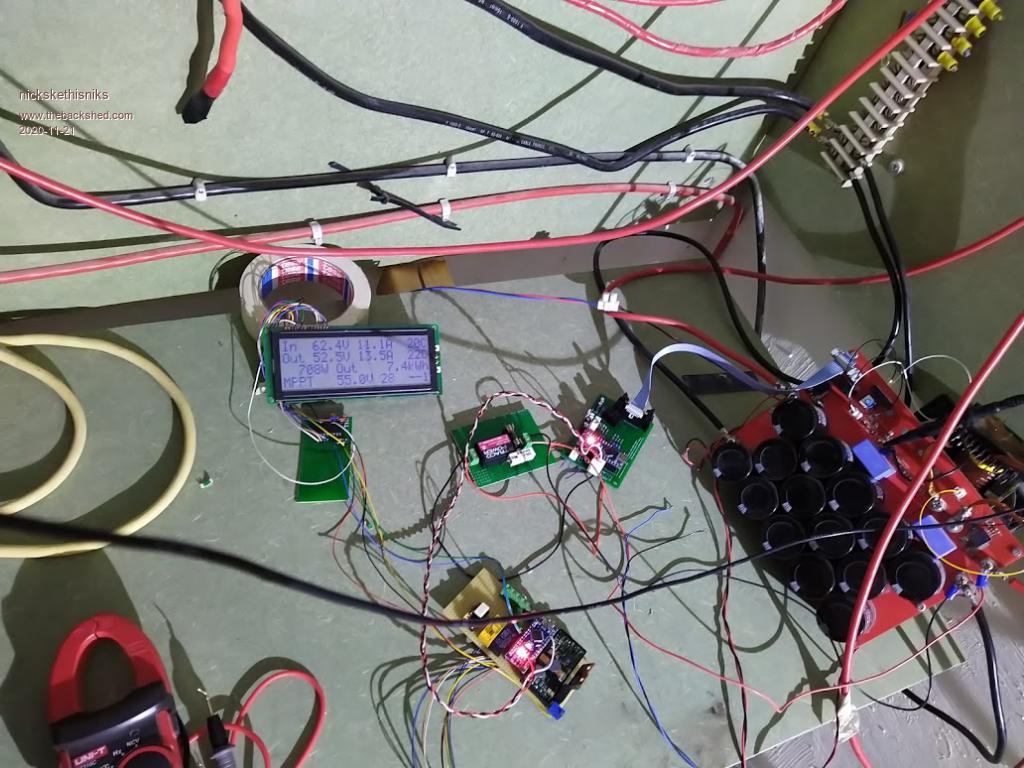
Evening energy harvest:
One thing I noticed was that the voltage-in was dropping under high power, I think this has to do with some things:
--> voltage drop in the cables + brakers, my testsetup is not well dimensioned --> there is a lot of 100hz voltage ripple in my system, there is also the backfeeding and loads that are creating voltage ripple and maybe upset the program. --> the inductor is not really designed for more then 30A, so it's probably saturating at this point. --> There is some ringing around the mosfet, about 15V-20V at high power levels on top of the input voltage. --> the driver power supply is providing more then 15V, so I probably need to adjust the gate resistors or lower this voltage. --> I need to check the resistor before my gatedriver, 1100R is to high, should be more like 390R for the FOD3182 --> the inductor is making a bit of noise when looking for the mpp, but I guess that's something physically. --> There is little time during the day my panels are not shaded, that's why I will use 3 controllers for the roof of my house.
Votage and current readings were verry stable, and the acs sensors were consistent, and need a stable voltage, I think there will be some drift under temperature changes, but it wont matter for the algorithm.
For the record I'm using 1000uF capacitors, I know the program was written and based on other parameters but it's really working great. I'm using a traco TEN-3-4812WIN power supply powered by my battery, it has 18-75V input range and 12V 250mA out, it's not cheap (12.5�) but should be reliable.
But the brainbord is realy a great thing, this makes my powerboard a very powerfull and programmable device, I'm verry verry satisfied with the performance! Edited 2020-11-21 06:24 by nickskethisniks
poida Guru Joined: 02/02/2017 Location: AustraliaPosts: 1387
Posted: 12:08am 21 Nov 2020
Copy link to clipboard
Print this post
Hi Nicks!
I'll try to answer some questions and comment on things. This is a big post of yours.
Yes, that is the way it is. For those of us using Wiseguy's board, the ribbon cable is located normally with the notches as indicated on the silkscreen. You and I Nick need to rotate one end 180 deg.
not a problem, I put 4.7uF cap across the TLP250 supply anyway. SMD sometimes allows piggyback components so it's easy to do on your board.
The 5V supply needs to be strong enough to do all the jobs needed: power uC power LCD and nano for LCD and give a repeatable and reliable 5V reference for ADC channel conversion.
I always calibrate with the external power supply via the 12V input of the brainboard present. This ensures 5V reference is available and good.
It's great to see you using the brainboard software. I am not surprised the LCD is unhappy with all the long wires and strong EMI.
The reason Voltage-in was dropping is due to the power verses voltage curve of solar panels. When taking small levels of power from a panel or array, the panel voltage will be nearly as high as open circuit. Once we take a lot more power from it, the panel voltage will drop to near maximum power point for that array.
As the sun changes angle to the array, this power/voltage curve changes too So early in the day, max power is found with higher panel voltages (65V) for these low levels of power available. Midday is max power so things change and max power voltage for the panel is lower.
I do not think is has much to do with the things in your list above but then the truth will be come evident in the fullness of time.
I do not like the 85C inductor temperature. That is a lot of waste energy heating the inductor.
Lastly I am very pleased to see that the program is working well. It appears this design has a large scope for varying key components and still operating well.
Feel free to alter the firmware to suit. In your case I would do tests for both heatsink and inductor temps and run a fan when limits are exceeded.
The ticking noise during the MPPT scan is when the firmware ramps up the PWM in steps from 5% to 95%. The step changes are sudden which excites a bit of high freq. oscillation of bits. Edited 2020-11-22 08:45 by poidawronger than a phone book full of wrong phone numbers
nickskethisniks Guru Joined: 17/10/2017 Location: BelgiumPosts: 409
Posted: 10:53am 22 Nov 2020
Copy link to clipboard
Print this post
Hi Peter, like I said my inductor is only rated for 30A maybe less, the newer inductors are better. And this is my main controller, but actually it's only the test version I like to abuse it verry heavily to be sure everything is bullet proof.
The final current will be shared between 3 controllers, they will each control a different string of panels, can you explain the "night power" to me? Is it to shut off the pwm?
Will imax reduce the output current to the battery, I think it is when I'm going thru your code?
poida Guru Joined: 02/02/2017 Location: AustraliaPosts: 1387
Posted: 11:01am 22 Nov 2020
Copy link to clipboard
Print this post
imax setting in the menu is a software limit which will be used to limit output current (by reducing PWM duty width until limit is no longer exceed)
I have found this limit is strongly followed. It is rarely exceeded, and if so only by a few percent for a second or two.wronger than a phone book full of wrong phone numbers
poida Guru Joined: 02/02/2017 Location: AustraliaPosts: 1387
Posted: 11:13am 22 Nov 2020
Copy link to clipboard
Print this post
Night mode is a shutdown of PWM.
During night mode once a minute a mppt scan is done, to see if it's worthwhile starting up the converter. If Vin is less than Vout (or battery voltage, same thing) then night mode is asserted and PWM is stopped. If Vin > Vout after a mppt scan then the converter keeps running.
WHEN RUNNING: It will run one of the 4 charge states (mppt, absorb, float or equalisation) depending on the user's settings and past run states.
It might take 2 mppt scans to start up from night mode in the morning. This is no issue at all. Edited 2020-11-22 21:19 by poidawronger than a phone book full of wrong phone numbers
renewableMark Guru Joined: 09/12/2017 Location: AustraliaPosts: 1678
Posted: 11:24pm 28 Nov 2020
Copy link to clipboard
Print this post
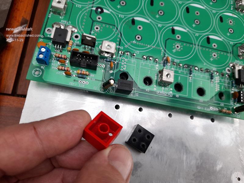
Finally putting this together. I found 2x2 lego blocks with the interlocking studs cut off make a nice stand off. They have an inner cylindrical sleeve too. Cheers Caveman Mark Off grid eastern Melb
renewableMark Guru Joined: 09/12/2017 Location: AustraliaPosts: 1678
Posted: 11:36pm 28 Nov 2020
Copy link to clipboard
Print this post
Lego is probably a good idea as you can make up whatever height you want too.Cheers Caveman Mark Off grid eastern Melb
Warpspeed Guru Joined: 09/08/2007 Location: AustraliaPosts: 4406
Posted: 12:15am 29 Nov 2020
Copy link to clipboard
Print this post
Now that is really clever !Cheers, �Tony.
renewableMark Guru Joined: 09/12/2017 Location: AustraliaPosts: 1678
Posted: 03:13am 29 Nov 2020
Copy link to clipboard
Print this post
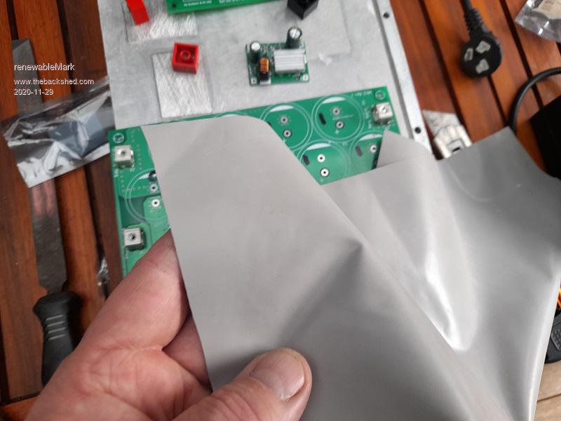
Peter, I gave you some of this stuff, is it OK to use for isolation?Cheers Caveman Mark Off grid eastern Melb
poida Guru Joined: 02/02/2017 Location: AustraliaPosts: 1387
Posted: 09:31pm 29 Nov 2020
Copy link to clipboard
Print this post
I used it for isolation of the 2 FETs and the two FET/diodes. It worked fine.wronger than a phone book full of wrong phone numbers
renewableMark Guru Joined: 09/12/2017 Location: AustraliaPosts: 1678
Posted: 09:15am 30 Nov 2020
Copy link to clipboard
Print this post
Cheers mate, so no need for a copper bar?
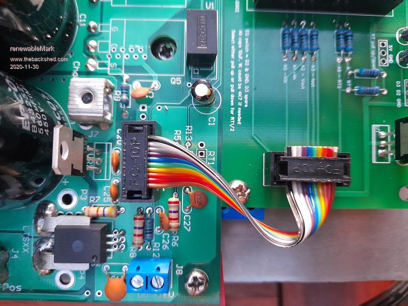
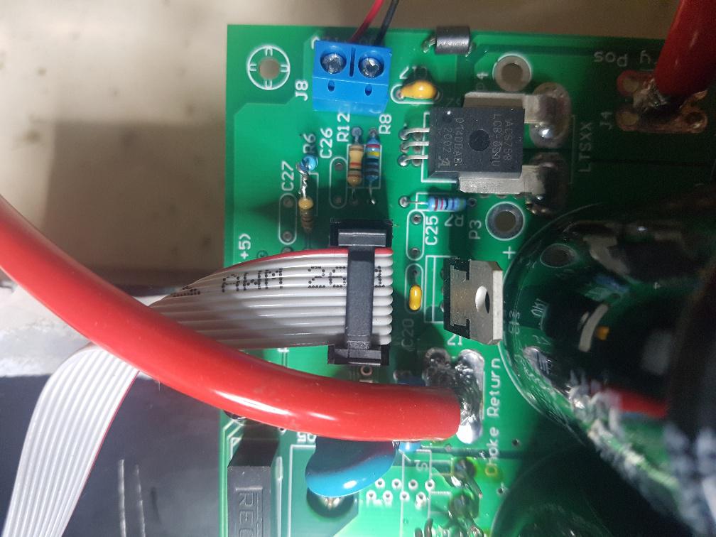
I'm getting closer to finishing, is that cable oriented the right way? I kept the same colour where the arrow goes on the plug when you make it up.
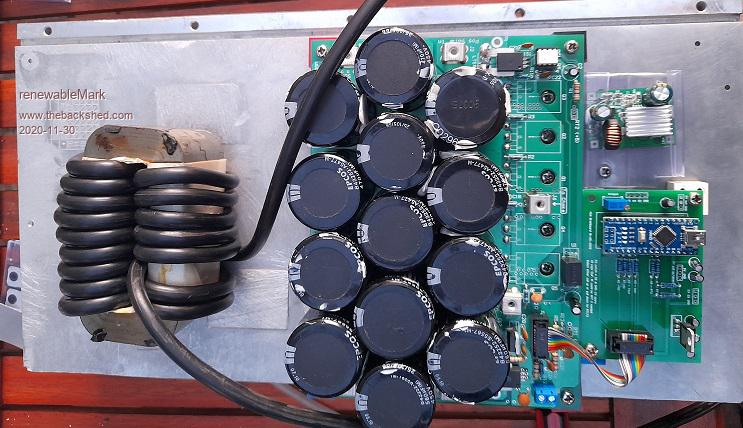
I found some 6 B&S or 13.5mm2, and got 17 turns, I can't find my inductance tester though. That size cable should be fine yeah?
Cheers Caveman Mark Off grid eastern Melb
renewableMark Guru Joined: 09/12/2017 Location: AustraliaPosts: 1678
Posted: 09:23am 30 Nov 2020
Copy link to clipboard
Print this post
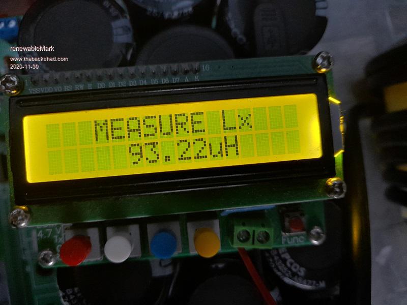
Found it.
I squeezed in one more turn and got 102uh Edited 2020-11-30 19:42 by renewableMarkCheers Caveman Mark Off grid eastern Melb
poida Guru Joined: 02/02/2017 Location: AustraliaPosts: 1387
Posted: 10:17am 30 Nov 2020
Copy link to clipboard
Print this post
when using wiseguy's boards, as you are Mark:
make a 10 pin IDC cable. Pin 1 goes to one end, as does pin 1 go to the other.
Note how the locating notch fits on the powerboard and the brainboard.
On the power board, the red wire is pin 1 and on the right. The locating notch faces LEFT in the photo.
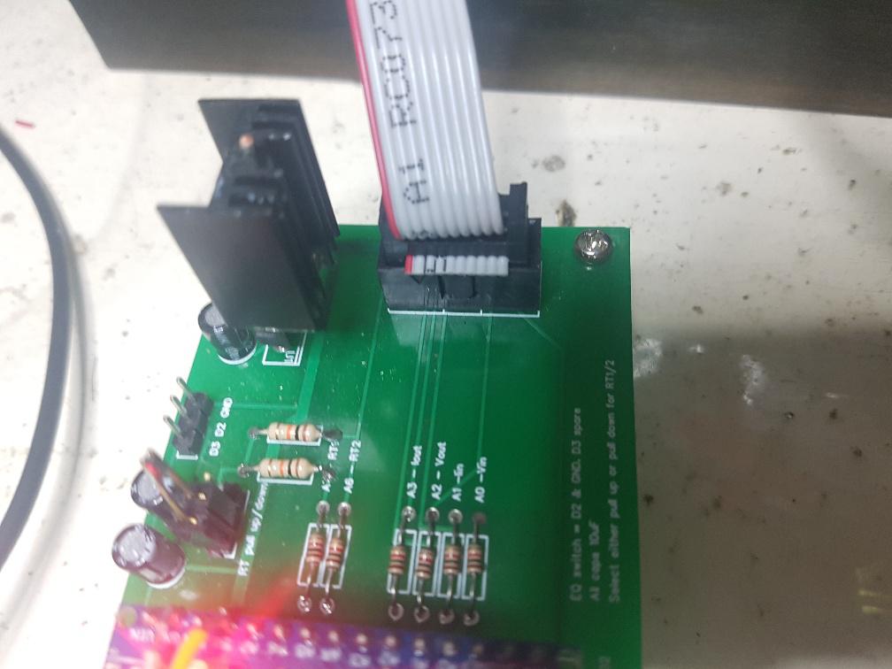
cable is now illustrated connecting to the brainboard. See how the notch is on the side leading to the nano.
It appears you have the cable orientated correctly.
If there is any doubt, use the multimeter and determine 12V and ground pins and see which pins are 12 and ground for both brainboard and powerboard. Getting 12V pins correct is all that is needed to get all the others correct.
No need for copper bar. Things do not get stupid hot, just warm. Edited 2020-11-30 20:26 by poidawronger than a phone book full of wrong phone numbers
renewableMark Guru Joined: 09/12/2017 Location: AustraliaPosts: 1678
Posted: 10:18pm 30 Nov 2020
Copy link to clipboard
Print this post
Hey Peter, I'm a bit confused. Earlier you tested a large aerosharp core with 16 turns and got 133uh.
I wound 18 turns and got 102uh.
So either my POS chinese meter is in fact a POS, or we are referring to turns a different way. I have been defining it as one pass through the centre.
Is that how you define a turn?Cheers Caveman Mark Off grid eastern Melb