
|
|
Forum Index : Electronics : 150V 45A MPPT - roll your own
| Author | Message | ||||
| flyingfishfinger Senior Member Joined: 12/09/2020 Location: United StatesPosts: 102 |
After some research, I have reason to believe that these chokes will not work as inductors here as Nick suggested. They're designed to handle the rated current for differential mode, not for common-mode use (I think, I might have gotten this backwards). However, I'm unclear whether there will be some improvement in the common-mode saturation current if I wire them such that the coils they are wound the same way, not opposite each other so the currents don't cancel - I'll try it out and see. R |
||||
| Warpspeed Guru Joined: 09/08/2007 Location: AustraliaPosts: 4406 |
Yes indeed. Noise suppression chokes are only made to work with a very few volts of high frequency ripple at the most, across them. Core loss will be negligible under conditions like that. They tend to burn up if you place several tens or hundreds of high frequency volts across them. If you know what the core material is, the data sheet should give some core loss figures. If its a salvaged unknown mongrel core, some testing will quickly tell you. For example, a 20 amp powdered iron filter choke salvaged from a large +5v dc computer power supply will probably not be terribly happy running in a 100+ volt solar buck regulator. Cheers, �Tony. |
||||
| flyingfishfinger Senior Member Joined: 12/09/2020 Location: United StatesPosts: 102 |
No worries, I wound a choke based on previous posts. Two questions for poida: 1) How does the software behave if the input voltage at MPPT is lower than the required battery charge voltage? Will it back off to charge at a sub-optimal higher voltage point, or will it stop charging altogether? 2) Do you have a version of the software handy which uses the I2C LCD in the main controller's Nano, not the "LCD interface" Nano? The MPPT code I downloaded (from the file 2020-09-08_101119_mpptv5_BV_tempco.zip) uses the UART buffer to feed the 2nd Nano. Cheers, R |
||||
| poida Guru Joined: 02/02/2017 Location: AustraliaPosts: 1388 |
mpptv5_BV_tempco_I2C.zip untested. It might work. the I2C address for the 20x4 LCD is 0x27 in the code. need to alter this if yours differs. wronger than a phone book full of wrong phone numbers |
||||
| poida Guru Joined: 02/02/2017 Location: AustraliaPosts: 1388 |
Once the input voltage is less than the battery's charge voltage setpoint the buck converter is stopped. The mppt IS a buck type dc-dc converter and so it can only convert a higher voltage to a lower one. It can not do anything if the input voltage is below it's required output voltage. It's not a boost converter, nor a buck-boost type. All mppt charge controllers I have looked at and built have a buck dc-dc converter design. Looking at a solar array's output For example, it might be 3 250W 35V open circuit panels in series. This gives about 105V DC output in strong light. And a battery could be a 48V nominal lead acid battery. WE need to convert the 105V to 54V for a reasonable charge voltage for the battery. The buck converter is ideal for that task at the power levels found with home built systems. The sun has set now and the array is making only 60 V. and with little current too. The buck converter can not do it's job without some voltage drop. I estimate about 1 volt. This places a lower limit on the input voltage for a given output voltage. For the 54V setpoint, I would see no point in even running the mppt controller if the input is less than 60V. Maybe you could get a few more Watts, maybe 10 Watts out of the 3 panels in series when illuminated with such low light levels. So I disable the converter and wait until the next day. The firmware checks for input voltage greater than setpoint every 60 seconds. If it's stopped in NIGHT mode and now greater, it starts up, usually in MPPT mode. If it was running in MPPT or ABSORB, and input drops below setpoint, it goes to NIGHT mode and stops the converter So that's the long story wronger than a phone book full of wrong phone numbers |
||||
| flyingfishfinger Senior Member Joined: 12/09/2020 Location: United StatesPosts: 102 |
Thanks for the files, I'll give it a try! For the other question - yes, buck converters only work when Vin > Vout + Vdropout - that's clear. That's pretty good from an electrical engineering perspective for something homebuilt / discrete, nice. What I was wondering about though, and your answer doesn't quite make clear to me yet is this: . If the device is running in MPPT mode and find the MPP is lower than the set point, it enters night mode, okay. However, then we're no longer drawing a load from the cells, so the voltage rises as we travel up the IV curve. Then we exit night mode.... wouldn't we then oscillate in and out of night mode? I must be missing something here, or is the above the accepted operating mode when conditions are marginal? R Edited 2021-09-03 09:17 by flyingfishfinger |
||||
| Warpspeed Guru Joined: 09/08/2007 Location: AustraliaPosts: 4406 |
What happens is the maximum power voltage never changes much from dark to mid day. What does change is the panels ability as a current source to supply current. What the MPPT software does is to increase/decrease the loading on the panels to hold the voltage at the max power point (whatever that voltage happens to be). As sun power diminishes at dusk the MPPT finds that to hold the voltage up, less and lass current is available. Eventually the duty cycle falls to zero. As it gets even darker, the voltage falls further, even though there is zero load current on the panels. It cannot cycle, it just slowly fades away and shuts down for the night. Cheers, �Tony. |
||||
| flyingfishfinger Senior Member Joined: 12/09/2020 Location: United StatesPosts: 102 |
Ok, that was the missing piece. So if the max power point is below the set point, I'm hosed either way. Thanks for the clarification! R |
||||
| tinyt Guru Joined: 12/11/2017 Location: United StatesPosts: 431 |
I had a project that has to communicate with I2C device. I only know a little C or C++ but more familiar with assembler. So I attempted to translate Atmel Appnote 315 and was able to use it. It uses interrupt mode which caused me to loose some of my side hair, top are gone way back. Here is I2C master write in polling mode. I don't know if this will help or create confusion. But here it is. .def mpr1 =r16 ; Multipurpose Register 1 /************************* From Atmel App note AVR315 **************************/ ;; General TWI Master status codes .equ TWI_START = 0x08 ;; START has been transmitted .equ TWI_REP_START = 0x10 ;; Repeated START has been transmitted .equ TWI_ARB_LOST = 0x38 ;; Arbitration lost ;; TWI Master Transmitter status codes .equ TWI_MTX_ADR_ACK = 0x18 ;; SLA+W has been tramsmitted and ACK received .equ TWI_MTX_ADR_NACK = 0x20 ;; SLA+W has been tramsmitted and NACK received .equ TWI_MTX_DATA_ACK = 0x28 ;; Data byte has been tramsmitted and ACK received .equ TWI_MTX_DATA_NACK = 0x30 ;; Data byte has been tramsmitted and NACK received ; ****vvvvv Main Code Section vvvvv****** ; etc. call TWI_Master_Initialise ; 100KHz clock call TWI_POLL_W ; Writes to I2C in hex (90 06 80 00 00 00 00 00 00 00) ; etc. ; ****^^^^^^^^^^^^^^^^^^^^^^^****** ;********************************************************* .equ SLA_W = 0x90 ; .equ SLA_R = 0x91 .equ CMD1 =0x06 .equ CMD2 =0x80 .equ CMDN =0x00 TWI_POll_W: ldi mpr1,(1<<TWINT)|(1<<TWSTA)|(1<<TWEN) sts TWCR,mpr1 wait00W: lds mpr1,TWCR sbrs mpr1,TWINT jmp wait00W lds mpr1,TWSR andi mpr1,0xF8 ; remove un-used bits cpi mpr1,TWI_START ; must be 0x08 breq TWI_POLL_SLA_W ; branch if yes jmp error_retW ; else error ;----------------------------------------- TWI_POLL_SLA_W: ldi mpr1,SLA_W sts TWDR,mpr1 ldi mpr1,(1<<TWINT)|(1<<TWEN) sts TWCR,mpr1 wait0W: lds mpr1,TWCR ; loops sbrs mpr1,TWINT ; till hardware makes jmp wait0W ; TWINT = 1 (see datasheet) lds mpr1,TWSR andi mpr1,0xF8 cpi mpr1,TWI_MTX_ADR_ACK breq TWI_POLL_CMD1 jmp error_retW ;-----------Fixed 06 ----------------------- TWI_POLL_CMD1: ldi mpr1,CMD1 sts TWDR,mpr1 ldi mpr1,(1<<TWINT)|(1<<TWEN) sts TWCR,mpr1 wait1W: lds mpr1,TWCR sbrs mpr1,TWINT jmp wait1W lds mpr1,TWSR andi mpr1,0xF8 cpi mpr1,TWI_MTX_DATA_ACK breq TWI_POLL_CMD2 jmp error_retW ;---------------Operation Mode --------------------- TWI_POLL_CMD2: ldi mpr1,CMD2 sts TWDR,mpr1 ldi mpr1,(1<<TWINT)|(1<<TWEN) sts TWCR,mpr1 wait2W: lds mpr1,TWCR sbrs mpr1,TWINT jmp wait2W lds mpr1,TWSR andi mpr1,0xF8 cpi mpr1,TWI_MTX_DATA_ACK breq TWI_POLL_CMD3 jmp error_retW ;---------------CMD3 (Reserved) --------------------- TWI_POLL_CMD3: ldi mpr1,CMDN sts TWDR,mpr1 ldi mpr1,(1<<TWINT)|(1<<TWEN) sts TWCR,mpr1 wait3W: lds mpr1,TWCR sbrs mpr1,TWINT jmp wait3W lds mpr1,TWSR andi mpr1,0xF8 cpi mpr1,TWI_MTX_DATA_ACK breq TWI_POLL_CMD4 jmp error_retW ;---------------CMD4 (Reserved) --------------------- TWI_POLL_CMD4: ldi mpr1,CMDN sts TWDR,mpr1 ldi mpr1,(1<<TWINT)|(1<<TWEN) sts TWCR,mpr1 wait4W: lds mpr1,TWCR sbrs mpr1,TWINT jmp wait4W lds mpr1,TWSR andi mpr1,0xF8 cpi mpr1,TWI_MTX_DATA_ACK breq TWI_POLL_CMD5 jmp error_retW ;---------------CMD5 (Reserved) --------------------- TWI_POLL_CMD5: ldi mpr1,CMDN sts TWDR,mpr1 ldi mpr1,(1<<TWINT)|(1<<TWEN) sts TWCR,mpr1 wait5W: lds mpr1,TWCR sbrs mpr1,TWINT jmp wait5W lds mpr1,TWSR andi mpr1,0xF8 cpi mpr1,TWI_MTX_DATA_ACK breq TWI_POLL_CMD6 jmp error_retW ;---------------CMD6 (Reserved) --------------------- TWI_POLL_CMD6: ldi mpr1,CMDN sts TWDR,mpr1 ldi mpr1,(1<<TWINT)|(1<<TWEN) sts TWCR,mpr1 wait6W: lds mpr1,TWCR sbrs mpr1,TWINT jmp wait6W lds mpr1,TWSR andi mpr1,0xF8 cpi mpr1,TWI_MTX_DATA_ACK brne error_retW ;---------------CMD7 (Reserved) --------------------- ldi mpr1,CMDN sts TWDR,mpr1 ldi mpr1,(1<<TWINT)|(1<<TWEN) sts TWCR,mpr1 wait7W: lds mpr1,TWCR sbrs mpr1,TWINT jmp wait7W lds mpr1,TWSR andi mpr1,0xF8 cpi mpr1,TWI_MTX_DATA_ACK brne error_retW ;---------------CMD8 (Reserved) --------------------- ldi mpr1,CMDN sts TWDR,mpr1 ldi mpr1,(1<<TWINT)|(1<<TWEN) sts TWCR,mpr1 wait8W: lds mpr1,TWCR sbrs mpr1,TWINT jmp wait8W lds mpr1,TWSR andi mpr1,0xF8 cpi mpr1,TWI_MTX_DATA_ACK brne error_retW ;---------------CMD9 (Reserved) --------------------- ldi mpr1,CMDN sts TWDR,mpr1 ldi mpr1,(1<<TWINT)|(1<<TWEN) sts TWCR,mpr1 wait9W: lds mpr1,TWCR sbrs mpr1,TWINT jmp wait9W lds mpr1,TWSR andi mpr1,0xF8 cpi mpr1,TWI_MTX_DATA_ACK brne error_retW ;--------------------------------------------------- ldi mpr1,(1<<TWINT)|(1<<TWEN)|(1<<TWSTO) sts TWCR,mpr1 ret ;-------------------------------------------------------- error_retW: ; does nothing ret ;-------------------------------------------------------- ;********************************************************* /**** The following is Atmel Appnote AVR315 re-coded in assembler ************* Call this function to set up the TWI master to its initial standby state. Remember to enable interrupts from the main application after initializing the TWI. ****************************************************************************/ ;-------------------------------------------------------------------------------- .equ TWI_TWBR = 84 ; Makes SCL = 100 KHz @ 18.432 MHz CLK: Division factor = (16+2*92*4^0) .equ TWI_TWPS = 0 ; should always be zero ;---------------------------------------------------------- TWI_Master_Initialise: ldi mpr1,TWI_TWBR ; Set bit rate (84) sts TWBR,mpr1 ; register for 100KHz SCL ldi mpr1,TWI_TWPS ; Pre-scaler should sts TWSR,mpr1 ; always be zero ldi mpr1,0xFF ; Default content = sts TWDR,mpr1 ; SDA released. ; /Enable TWI-interface and release TWI pins / Disable Interupt/No Signal requests. ldi mpr1,(1<<TWEN)|(0<<TWIE)|(0<<TWINT)|(0<<TWEA)|(0<<TWSTA)|(0<<TWSTO)|(0<<TWWC); sts TWCR,mpr1 ; do it. ; ; ret ;------------------------------------------------------------- Edit: added definition for mpr1 Edited 2021-09-03 10:11 by tinyt |
||||
| Warpspeed Guru Joined: 09/08/2007 Location: AustraliaPosts: 4406 |
O/k assume its sunrise, max power voltage is 100v, and the voltage across the solar panels is slowly increasing. Its risen to maybe 35 volts and the electronics is alive. MPPT takes its first tentative step and increases the duty cycle from 0% to 1% and measures the power. ts a whopping 50 milliwatts. MPPT takes another step and increases the duty cycle to 2%, power falls to 40mW. Opps, overloaded the panels, return to 0% and try again. It then cycles as the sun rises and power increases, but every time it tries to increase the duty cycle and the load, power decreases. Eventually this cycling continues until the panel voltage reaches 100v, loading up to this point will be negligible, and power output almost zero. Once we get to the magic 100v, the MPPT finds it can actually start seeing a power increase as the duty cycle increases further, not a decrease. So it rocks the duty cycle back and forth. If power increases, increase duty cycle up a notch, if power decreases, reduce duty cycle. So it zigs and zags up to solar noon. Pretty much the reverse happens in the afternoon, and duty cycle slowly reduces keeping the voltage at close to the magic 100v, the peak in the power hump. At dusk duty cycle will essentially fall to zero with the voltage still up near 100v. Beyond that power will be zero and the voltage falls away as the sky darkens. Cheers, �Tony. |
||||
| Warpspeed Guru Joined: 09/08/2007 Location: AustraliaPosts: 4406 |
At any panel voltage below the rated max power voltage, any extra loading reduces power. At any panel voltage above the rated max power voltage, any extra load will produce a measured power increase. MPPT software is constantly seeking that hump in the curve, and it will allow the voltage to rise to the top of the hump BEFORE it tries to draw any power at all. The maximum power voltage absolutely must be higher than the maximum battery voltage. You cannot charge a 48v battery from a 12v panel. And you cannot charge a 48v battery when a 48v panel is well below its full voltage. Edited 2021-09-03 10:32 by Warpspeed Cheers, �Tony. |
||||
| phil99 Guru Joined: 11/02/2018 Location: AustraliaPosts: 1776 |
There were some cheap MPPT chargers that didn't actually track the peak, but estimated it based on the panel manufacturers specified I and V at max. power. With less than maximum solar input they would simply adjust the pulse width to maintain the same ratio of actual V / I to that of Vmax.p / Imax.p. With most panels this is a reasonable approximation. |
||||
| Warpspeed Guru Joined: 09/08/2007 Location: AustraliaPosts: 4406 |
That actually works very well. Its rather like having a shunt voltage regulator across the solar panels, it draws whatever current is available, maintaing a constant panel voltage. Peak power voltage is not a sharp peak, but a very broad wide hump. For that reason, you will lose very little recoverable power if the voltage set point is not exact. The voltage on the panel rating plate will be very close to optimum. Cheers, �Tony. |
||||
| poida Guru Joined: 02/02/2017 Location: AustraliaPosts: 1388 |
The firmware searches for max power output going into the battery using the range of PWM duty % from 5% to 95%. The search notes which duty width gave the highest power output on the battery terminals and call it maxpwm. The search is done once a minute. Since there is always less power with PWM widths that are smaller than maxpwm and power levels LESS than max power at PWM widths > maxpwm the control code is simple. This search is not performed while Vin < Vout There is no point. The buck converter will only give an output voltage of Vout which is the battery voltage. We will see on Vin a voltage no less than the MOSFET body diode Vforward voltage subtracted from Vout (battery). Since Vin is hooked up to panels, and those almost certainly have diodes to prevent reverse conduction, then the voltage at Vin is going to be (Vout - MOSFET Vf) and I ignore the panel diodes leakage current. So Vin < Vout means no mppt search. Probably nighttime or something or I opened the solar array contact breaker. As far as V/I curves of panels when output voltages are low due to darkness or low light, for sure, there might be small current flowing into the controller, enough to charge the input caps above Vout and so on occasions the controller will do a search. Since there is only a small current input at panel voltage, the input caps will discharge far faster than the small current can sustain during the scan and so Vin will drop during the mppt scan. The controller might startup and run, but a timeout will trigger the Vin < Vout condition and so stop the converter and call it NIGHT again. This is not much of a problem for me in practice. here is data from the MorningStar 60A MPPT controller I had first before the home built mppts. I show what it calls Sweep Vmp and Sweep Voc (V max power and V open circuit) They use a different scale than battery voltage. They are also maximum values found during the mppt sweep. So it's likely Voc was maximum at the start of the sweep when very little power was sent out to the battery. But once the dc-dc converter starts, the input voltage surely drops to BV - MOSFET/diode drops During the early morning Voc was 53.17V, battery was 48.46V so let's rock and roll and make power! The power generated then was 10W. I think you are examining these borderline conditions, am I correct? 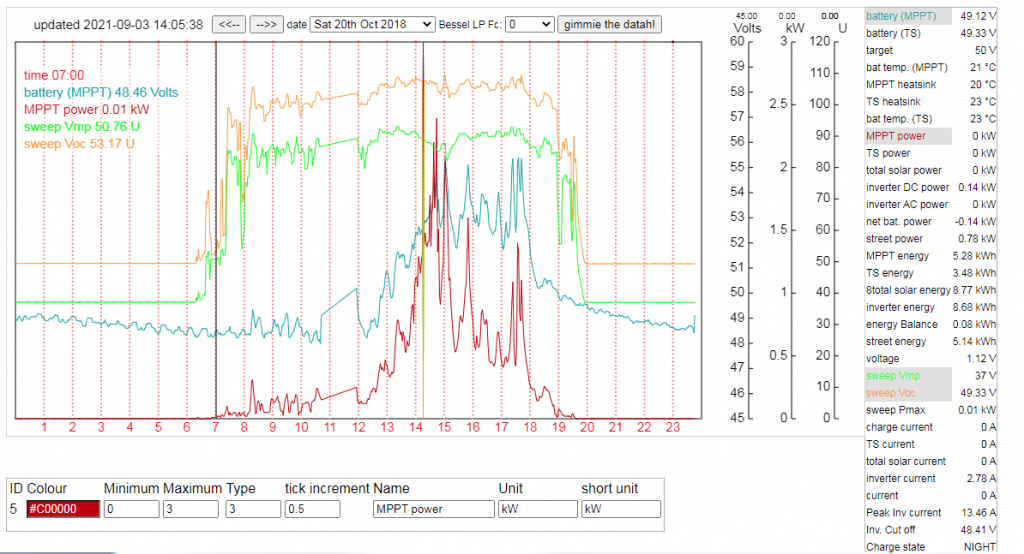 Similarly, data for my mppts is below: 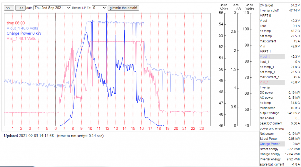 we can see Vin is about 0.5V less than Vout (or battery, same thing) at 6am when it is still rather dark here. Note again different voltage scales. The vertical line is at 6am and the exact values are shown on the left side at that time. Please ignore the charge power curve. It is the sum of two 3kW arrays, one not making any power, the other doing most of the work. I can explain what's going on with this curve but that will be a long story and we can't have much interest in that right now... My mppts will be checking every minute at all times if Vin > Vout. IF so, do the mppt scan and run the converter If not, wait a minute. wronger than a phone book full of wrong phone numbers |
||||
| paulina1 Newbie Joined: 30/09/2018 Location: RomaniaPosts: 2 |
Hello, I'm a beginner, I would like this project too, but I would like for 24 volts, how could I program this MPPT. |
||||
| poida Guru Joined: 02/02/2017 Location: AustraliaPosts: 1388 |
Hi Paulina1 This will work fine with 24 V output. For good efficiency I would want to design the solar array to give no more than about 2 times your desired output voltage. e.g. for my system the 48V battery needs up to 55V maximum output and my panels are wired to give about 100V open circuit and about 80V at maximum power. For the panels I have I needed to have 3 panels in series. Using only 2 panels in series would give a too low output voltage. The mppt firmware is easy to change to 24V. Connect to the serial console and input the required values.. wronger than a phone book full of wrong phone numbers |
||||
| paulina1 Newbie Joined: 30/09/2018 Location: RomaniaPosts: 2 |
thank you very much |
||||
| poida Guru Joined: 02/02/2017 Location: AustraliaPosts: 1388 |
So, I busted my back yesterday and then that means time laying on your back with nothing to do. While there I worked out a lurk to make the mppt protected against short circuit on it's output. As you probably know I played with OC protection in the earlier versions and discarded it since it did not work very well. It looked for a high current signal from a current sensor placed on the lead coming from the MOSFET Source pin going to the inductor. This is where you must measure the MOSFET current. The sensor output was put into the Nano's comparator input and at the start of each PWM pulse, I would check the comparator bit and disable PWM output if the current sense signal was larger than a setpoint. It worked, sometimes. Other times it blew the two MOSFETs. The new idea is to disable the PWM signal using analog means. I have the same current sensor in the same location. This time the output goes into an IRFZ44 MOSFET that is across the PWM output from the Nano. If it's gate goes above about 3.2V then the FET shorts the PWM output to ground. It is fast. I have shorted the output of the mppt board many times, ripping holes in the screwdriver in the process. I use a LEM 25 Amp bipolar sensor. This means the signal is 2.5V with zero current. In the location it's fitted, it only sees positive current so the signal is always above 2.5V. At about 25 Amps the IRFZ44 switches on enough to shunt the PWM drive to ground. So, 2 components. A trimpot and the LEM current sensor. I shunt the PWM output at the Nano's output (it can handle a short on 1 digital pin but not shorts on ALL digital pins at the same time.) This work was done not for the mppt project but it can apply to this. It was for a home brew charger for the electric bike. I want something that can do 54.3V at 10 Amps and be immune to inadvertent shorts and other dumb things. The mppt board is ideal for this, when fed via a large IE tranformer and diode bridge, both of which I have at hand in the workshop. Or just get something from Aliexpress. Anyway, the over current protection works really well. Probably work fine with Allegro sensors too. wronger than a phone book full of wrong phone numbers |
||||
| Warpspeed Guru Joined: 09/08/2007 Location: AustraliaPosts: 4406 |
That is excellent Peter. The LEM is definitely fast enough, and the galvanic isolation will go a long way towards isolating noise pickup that might otherwise cause false tripping. Cheers, �Tony. |
||||
| poida Guru Joined: 02/02/2017 Location: AustraliaPosts: 1388 |
ta Warp. Here is some more info. First, the current sensor outputs a voltage, maybe able to drive 20mA that ranges from 0 to 5V. For zero current, voltage is 2.5V I use a pot to divide this voltage down to where the FET Gate threshold is starting to be reached by the current sensor output voltage. So now the Gate is getting a small fraction of the 20mA and this means the Gate now takes time to charge (due to Gate capacitance). It's not ideal but it still works.. Should I do this for a proper project I would find a fast opamp to buffer the current. Here are some DSO captures of the short on the output event. Yellow is PWM signal going to the TLP-250 input diode Purple is the current sensor output after the trimpot divider, which is also FET gate voltage. Light Blue is not connected. This is the event before & during the short. The graph is not nice to see due to the huge time compression. No idea why the current is constant during transition period. Would it not increase steadily? (edit: this is due to the time taken for the "switching" of the screwdriver short-out. Sometimes there is no transition 'cos I was much faster with the screwdriver) 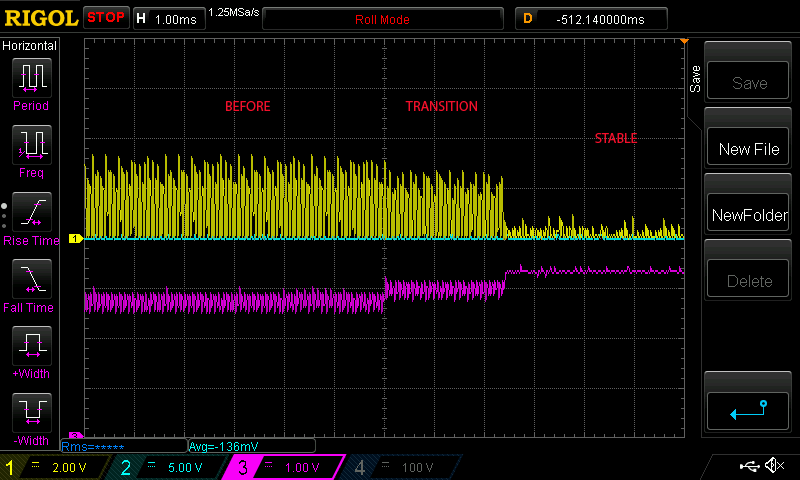 Close up of before short. 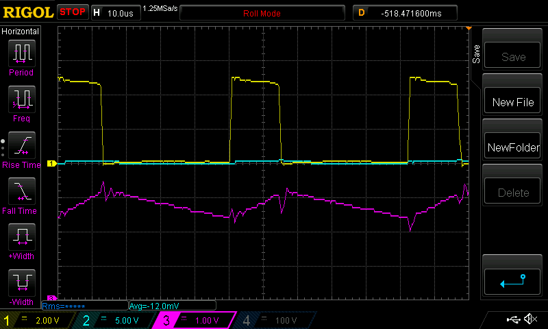 Transition. 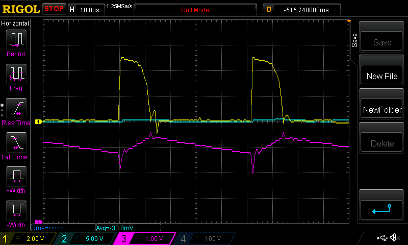 Close up when things are stable. It's alternating a short pulse then a nearly nothing pulse. 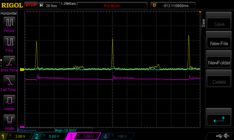 You can see the current sensor output/Gate voltage rise to the required voltage for the IRFZ44N to conduct the 5V PWM drive This voltage appears to be 3.3V or thereabouts. The specs say 2.0 to 4.0 V. Ok that's a wide range.. It's satisfying to see the LCD show correct output voltage and current during the short. It shows 0.0V output, which is correct. IT might be something like 0.01V but that's not important. And it shows 24.5A as output current. This is good info for the PWM control loop code, I think I can detect a short by looking for this combination of values (0V and Lots of Amps) Finally here is a capture of when the screwdriver made contact. (the Gate voltage now shows effects of too low drive current thanks to the trimpot's setting. I had it set at about 35 Amps max current) 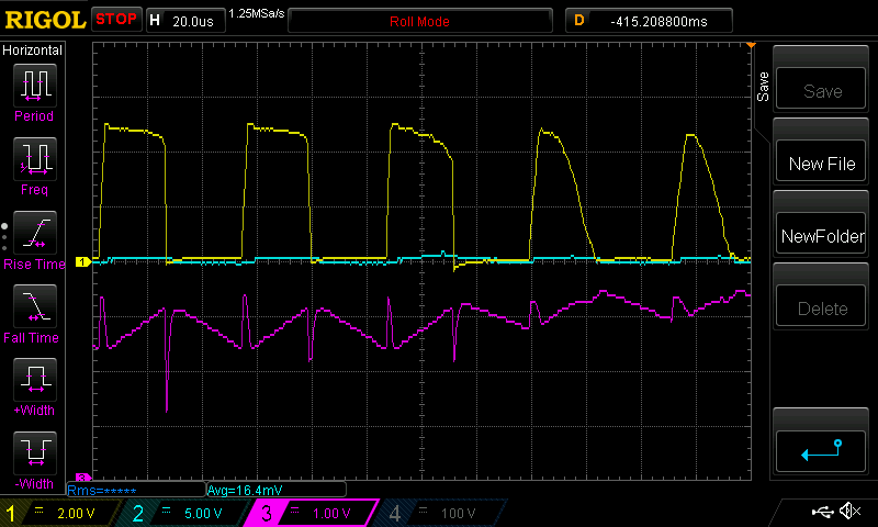 The left most pulses are when inductor current is below 35 Amps The middle pulse is the first to be altered by the FET And the last 2 are clearly getting smaller. (For those who may not know, pulse width is proportional to inductor current. Longer pulses means higher current) Since the Gate voltage trace is 1V/div, and the threshold is about 3.3V the equivalent current is 10 Amps/div approx. We can see the current rise rise from about 25A to 35A over 5 pulses or 250 uS The combined response time of the LEM sensor and the FET seem to be more than fast enough for this task. I feel this scheme can be used in our inverter, mppt and other switching power designs to protect against short circuit or overloads. I see no reason why the LEM sensors must be used either. So we can use cheaper parts. Here is is again with output voltage in Light Blue. This was a faster switch event. Output voltage was 18V. 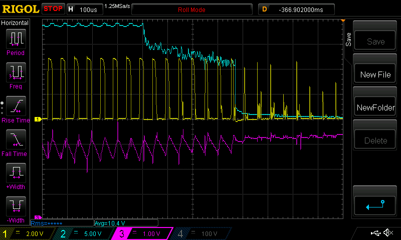 Edited 2021-10-11 11:21 by poida wronger than a phone book full of wrong phone numbers |
||||
