Notice. New forum software under development. It's going to miss a few functions and look a bit ugly for a while, but I'm working on it full time now as the old forum was too unstable. Couple days, all good. If you notice any issues, please contact me.
Warpspeed Guru Joined: 09/08/2007 Location: AustraliaPosts: 4406
Posted: 01:20am 11 Oct 2021
Copy link to clipboard
Print this post
How's the back Peter ?Cheers, �Tony.
poida Guru Joined: 02/02/2017 Location: AustraliaPosts: 1387
Posted: 02:49am 11 Oct 2021
Copy link to clipboard
Print this post
Better each day. I need to be able to work tomorrow. And fold in 1/2 to get in the MX5 to drive to work. I don't think it was a disk, I think only muscle strain.wronger than a phone book full of wrong phone numbers
Warpspeed Guru Joined: 09/08/2007 Location: AustraliaPosts: 4406
Posted: 02:54am 11 Oct 2021
Copy link to clipboard
Print this post
A soak in really hot bath usually works for me for those types of problems. What MX5 do you drive ? I have a a white 99' NB1Cheers, �Tony.
poida Guru Joined: 02/02/2017 Location: AustraliaPosts: 1387
Posted: 10:11am 11 Oct 2021
Copy link to clipboard
Print this post
Warp: A 99 NB with 310,000km on it, broken everything but it runs. And leaks a bit of oil out of all ends. Busted bodywork but that suits me nicely. I get free fuel from work and I have had the car since 2005 so it costs me not much more than $1K per year. I am now thinking of a KTM RC390 motorbike. Already I have a 900 Superlight Ducati but the KTM seems a good fit for getting to work.
Anyway, back to the subject at hand..
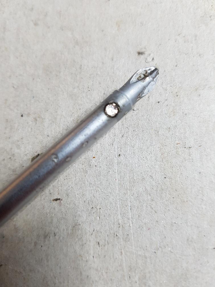
The damage to the screwdriver:
All in the name of science. (as Photinicinduction would say)
Code changes now look for a short and modify the PID loop whilst shorted. This prevents voltage overshoot when the short is removed. This is a great start for a home brew big current, big voltage power supply for the bench and ebike charger. I want well over 60V and 20 Amps and for it to be indestructible.wronger than a phone book full of wrong phone numbers
noneyabussiness Guru Joined: 31/07/2017 Location: AustraliaPosts: 506
Posted: 09:42pm 13 Oct 2021
Copy link to clipboard
Print this post
reminds me of the time I dropped a screwdriver on a 48v bus bar before the fuses... literally made the section between contact points disappear, never found it..
and it was a big screwdriver...
lesson learned, moved + and - much further apart..I think it works !!
poida Guru Joined: 02/02/2017 Location: AustraliaPosts: 1387
Posted: 06:33am 14 Oct 2021
Copy link to clipboard
Print this post
Noneya, big current can be impressive. And when it's DC, it is even a better show. My only, so far, mistake was to let a nice 13mm ring spanner short a + and - on a 4 x 200AH SLA bank at 24V. It only just chewed a little off the side of the handle.
During testing of the above, I had the firmware not looking for short circuit and just trying to attain the voltage setpoint, while the FET/current sensor thing was doing it's thing. I could set the OC protection to about 35 Amps and let the screwdriver graze a conductor and nearly maintain an arc. 35 Amps at less than 0.5V is not impressive but it still bites a hole in the metal.
All this and not blowing up 2x nice MOSFETs. Maybe I could adapt this to be a TIG welder..probably not.wronger than a phone book full of wrong phone numbers
poida Guru Joined: 02/02/2017 Location: AustraliaPosts: 1387
Posted: 10:57am 01 Nov 2021
Copy link to clipboard
Print this post
Milestone time again. I must again thank you all here for your help in developing this project.
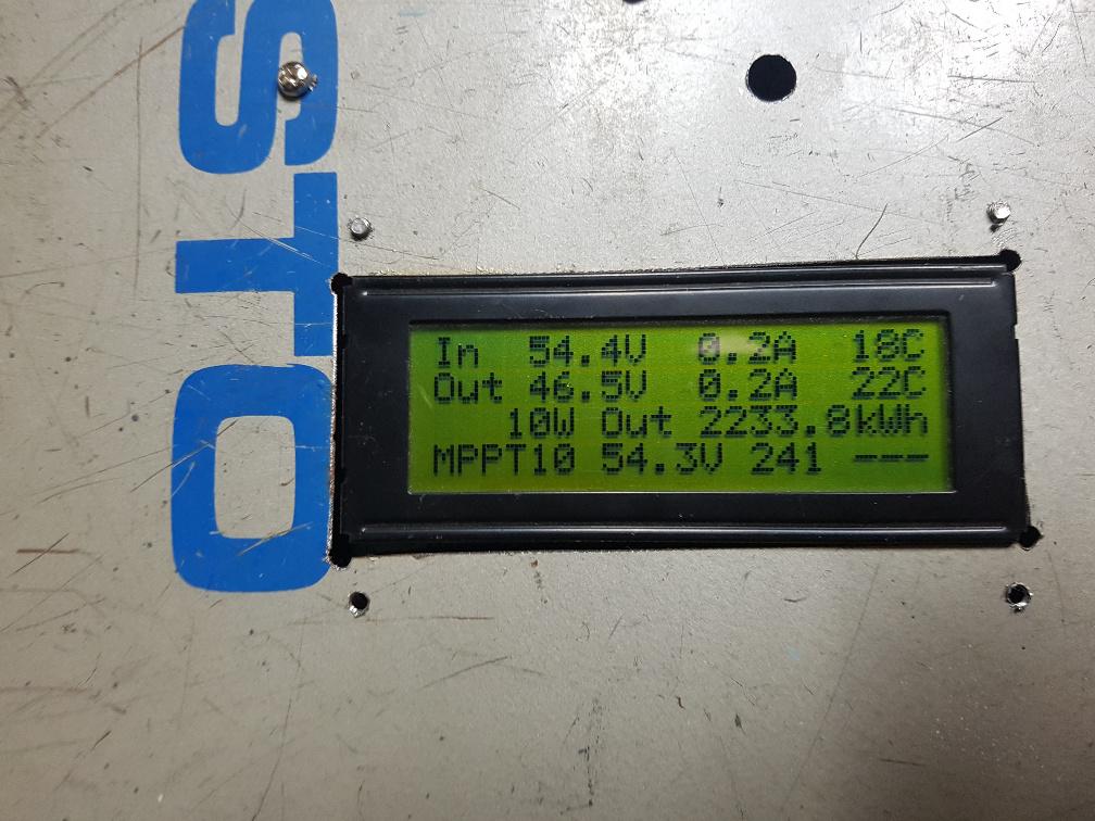
I run two of these mppt controllers. One has a 3kW array facing East One is 3kW facing North.
The East facing array:
and the North facing array:
They just work and work well.
3 MW.hr of energy has passed through them. And with an efficiency better than 92%, frequently in the 95%.
Heat sink temps never more than 35 - 40 C The North array mppt controller gets to 45 Amp limiting conditions often, but for short periods of time now it's nearly Summer.wronger than a phone book full of wrong phone numbers
poida Guru Joined: 02/02/2017 Location: AustraliaPosts: 1387
Posted: 04:10am 26 Jan 2022
Copy link to clipboard
Print this post
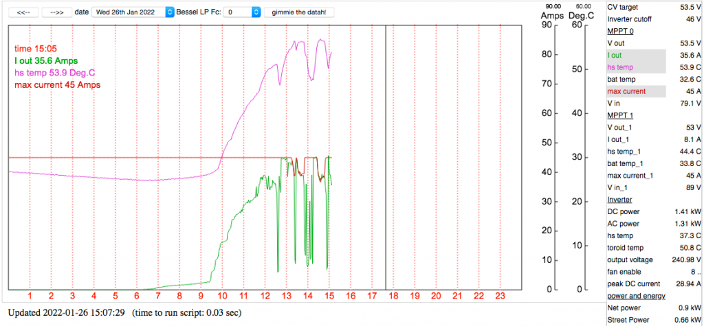
Today it is hot. the mppts are working well and I have one doing a lot of work and so the heat sink is getting hot. I have the output current throttle setting to start at 55 DegC to reduce output current limit from 45 Amps to zero Amps at 65 degC
It works well. We can see the output limit become lower as the HS temp exceeds 55 degC and the output current flow suit, never exceeding it. It's also a bit cloudy so there is not enough power some times.
data from today so far: output current is Green Heat sink temp is Purple Output current limit is Orange
wronger than a phone book full of wrong phone numbers
poida Guru Joined: 02/02/2017 Location: AustraliaPosts: 1387
Posted: 07:39am 30 Apr 2022
Copy link to clipboard
Print this post
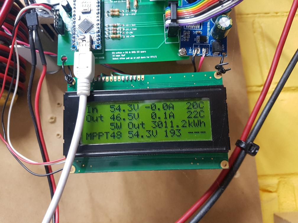
milestone time again
5 MW.Hr from the two mppt controllers. Both working without any issue So pleased to see this
I can reconfigure them while they are running via the serial ports that are connected to the raspberryPi and I did this remotely from work.
It's 5:40pm here in Melbourne and it's early evening light levels.
wronger than a phone book full of wrong phone numbers
Murphy's friend Guru Joined: 04/10/2019 Location: AustraliaPosts: 580
Posted: 08:31am 30 Apr 2022
Copy link to clipboard
Print this post
HaHa, funny typo, one would think you have a personal power station there .
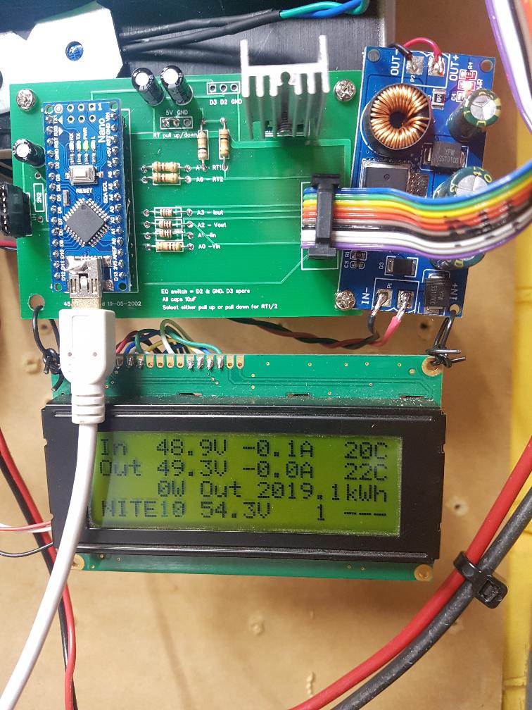
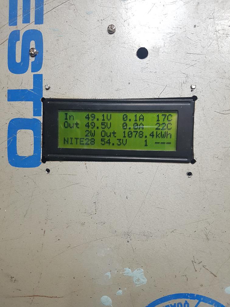
Your two MPPT's are a lot busier than my single one. It just passed 1100KWh, running with no problems. Back when we had those really hot days the fan came on a few times but had no trouble cooling it while it was charging at 50Amps.
This project was a lot quicker to get going than my inverters were .
ryanm Senior Member Joined: 25/09/2015 Location: AustraliaPosts: 191
Posted: 11:12pm 30 Apr 2022
Copy link to clipboard
Print this post
Not a typo. A thousand kilowatt hours is a megawatt hour.
flyingfishfinger Senior Member Joined: 12/09/2020 Location: United StatesPosts: 102
Posted: 06:22pm 12 May 2022
Copy link to clipboard
Print this post
So I finally got around to firing up some test code. First off, it works! Yay!!! But I have some questions.
I'm using the code that was posted for testing, the DCDC converter code (buck_converter_nics_1_b4_nano_pwmserial_bb), but I modified it for use with my Nanocontroller with I2C LCD.
Upon running it, I found that both the input and output voltages read by the Nano do NOT correspond to the actual voltages. The input voltage seems to read a good ~10V higher than it actually is. Also, the current readings are negative.
I've checked my input (and output) voltage dividers, they're correct according to the Powerboard BOM & schematic I have (R5 & R7 are 47k, R6 and R8 are 2.7k).
But that means the scaling coefficients in the code are wrong (also, if the voltage dividers for Vin and Vout are the same, why are the scaling coefficients different?). For xVin the code has 0.1564 and for xVout it has 0.102. The latter is NEARLY right, it results in the reading being about 1V too high.
Then I saw one post where you said it should be 1k and 47k to get a higher input voltage range, but the xVin coefficient doesn't work for that either.
So I "fixed" the coefficients and put in xVin=0.234 (using the 1k resistor) and xVout=0.09 (using the 2.7k resistor).
For the current sensors, the coefficients are also odd. The offset should be 0.6V, but is set in the code (oIin and oIout) to 127, which is a bit higher than 0.6, so the "zero" current reading is negative. I reduced it to 122. Then, the scaling seems a bit off as well: An ACS758 which I have used puts out 60mV/A over a 5V range, so the scaling should be 0.0816 instead of 0.792...I think.
These are better, but I think I can dial them in even closer.
Question: Were these values meant for different current sensors or a different setup?
I tested this up to 120W for the moment, since my benchtop power supply will only put out 5A.
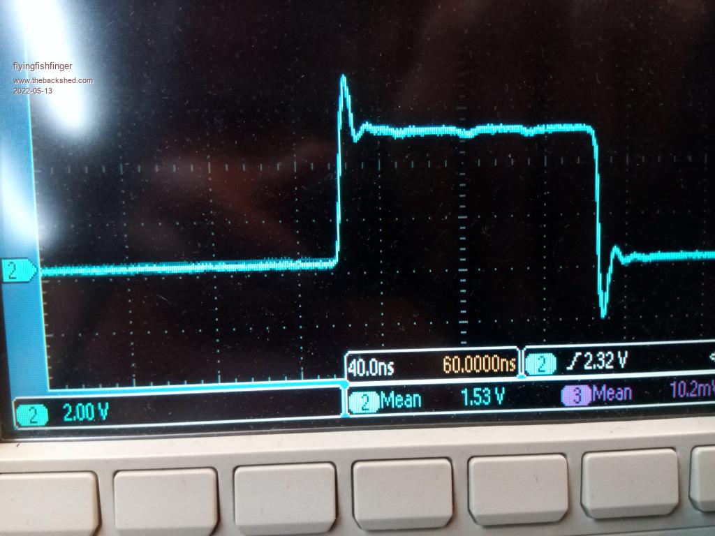
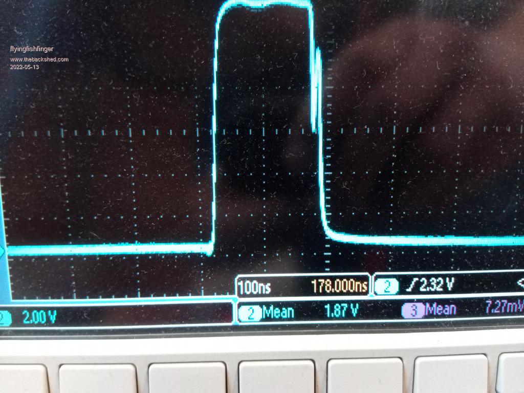
I checked out the PWM waveforms. Out of the Nano:
Output of the optocoupler before series resistor (note different time scale):
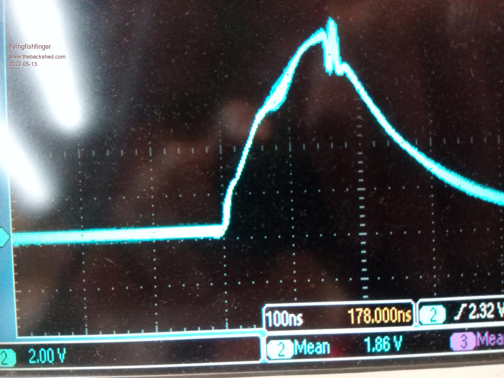
Gate of the MOSFETS (after series resistor). This one looks odd, but after reading the datasheet for the FDH055N15A, it's actually not that bad. The normal turn-on delay is 35ns and the turn-on time is supposed to be 67ns....which is about what we see here.
Question: 100ns on time seems very short for this MOSFET. But these screenshots might have been measured with NO load, so having basically 0% duty cycle makes sense for this case. Am I right there?
How do you characterize inductor saturation? Shunt / clip current probe? Will look at it again under load.
Thanks, Rafael Edited 2022-05-13 11:57 by flyingfishfinger
poida Guru Joined: 02/02/2017 Location: AustraliaPosts: 1387
Posted: 10:46am 13 May 2022
Copy link to clipboard
Print this post
you need to change the calibration factors within the code to suit. eg: Vin reading is 50V but measures 40V so you alter factor for Vin by 40/50 X existing value
I have done this numerous times for the 4 different board I built.wronger than a phone book full of wrong phone numbers
poida Guru Joined: 02/02/2017 Location: AustraliaPosts: 1387
Posted: 11:00am 13 May 2022
Copy link to clipboard
Print this post
the values were for my particular boards. they are not meant for anything in particalur.
I figured others who might use this would use actual volt meters on input and output and current sensors etc and measure what they find. This is what you have done already and it's the way to go.
The 100ns on time is not meant to do anything at all just keep running as it were. This is a minimum PWM width and probably generates very little output voltage.
Typical PWM widths can be calculated from your DCV input and DCV output. It is the ratio of Vin and Vout eg. 60V in 30V out PWM will be 30V/60V or 50% or about 400 clocks or 10us approx. This is a reasonable working value for PWM In my case it's more like 75V in, 50V out so it's 50/70 or about 570 clocks (I've had a few drinks and so the maths could well be RONG)
the waveforms look fine and include some inductance from the CRO lead earth clips I think. This is not a problem.wronger than a phone book full of wrong phone numbers
flyingfishfinger Senior Member Joined: 12/09/2020 Location: United StatesPosts: 102
Posted: 12:24am 17 May 2022
Copy link to clipboard
Print this post
Cheers! Thanks for the feedback / confirmation. Still need to find a good heatsink, ugh.
How much power do you reckon will go through a well-wound inductor? I'm about to install (theoretical max) 3.6kW of solar and really hoping I can get away with one of these.
R
poida Guru Joined: 02/02/2017 Location: AustraliaPosts: 1387
Posted: 03:27am 17 May 2022
Copy link to clipboard
Print this post
how much power? no idea
but you can find out how your inductor is going to go at different power levels though. That is what I did in some earlier posts in this thread.
The test code (buck_converter or something )takes the voltage from A5 which is the set point for output voltage and drives the pwm to produce that output voltage.
I started with low voltages output into an approx 1 Ohm resistor and used a current sensor to see inductor current.
Just playing with the pot. gave great insight into what power levels and what Vin did to saturation. I suggest you do the same. After an hour of playing with high power levels you will see how hot the heatsink gets and how hot the choke gets.
The resistor was 3 lengths of 6 foot long 0.8mm stainless steel MIG welding wire, wrapped around a bit of wood in a 20 litre bucket of water. This could take 3kW with ease for 1/2 an hour
The final version of the mppt code will throttle back the output power as the heatsink reaches and exceeds some max temp. I use 55C as start of throttle and if it gets to 65C then it's completely stopped. This makes it bullet proofwronger than a phone book full of wrong phone numbers
flyingfishfinger Senior Member Joined: 12/09/2020 Location: United StatesPosts: 102
Posted: 05:30pm 05 Jun 2022
Copy link to clipboard
Print this post
Hi, Got my setup running! Will post pictures later, it's been raining the past two days so I haven't been able to put much wattage through the thing.
I do have questions about the voltage levels though. In your presets, you have absorb set to 13.5V and float at 13V.
From what I understand, absorb should be around 14.4V for lead acids and float back down around 13.5-13.8V.
Second, why does the charger switch to absorb at (tolerance) BEFORE the absorb set point? Shouldn't it only do that to get back to MPPT, not to get into absorb initially?
For example, in your default settings, absorb will start at 12.9V and taper off all the way until 13.5V, but with the absorb time it will only do this for an hour. That may not fill the battery.
Shouldn't lead acids be charged at full current all the way until the 13.5V, then taper off the current like in this diagram:
Cheers, R Edited 2022-06-06 03:35 by flyingfishfinger
poida Guru Joined: 02/02/2017 Location: AustraliaPosts: 1387
Posted: 06:36am 06 Jun 2022
Copy link to clipboard
Print this post
first, I need to have some values, anything, just to give you the idea of what it is.
Clearly, you need to change things from the default values, which are no use to you nor anyone. My system is 48V so the defaults are rubbish for me.
I have a tolerance value for both absorb and float since it is easy for a cloud or something to reset the absorb or float timer unnecessarily
my intentions for the firmare are: starting from a discharged battery and enough solar the mppt will first run at MPPT mode until battery gets to (ABSORB - tolerance)
And then the controller will keep the battery at (ABSORB - tolerance) if it can for the period defined at ABSORB TIME. IF not enough sun, then the abosrb timer is reset to zero when the battery drops below (ABSORB-tolerance)
so MPPT is only used when there is not enough sun to get to (ABSORB-tolerance)
Float will happen once the battery stays at or above (ABSORB - tolerance) for ABSORB TIME with no dropouts. The controller will keep it at (FLOAT - float tolerance) for ever. But we will always run out of sun so the battery drops below (FLOAT - tolerance) so triggering MPPT mode which may or may not bring it back to absorb But since this is night time it doesn't matter if a bit of time is again spent at ABSORB.
We discharge the battery overnight and it all starts again.
Set your values to suit your battery and situation.
I have something like 3 hours for ABSORB time It does not get to float very often, only when we holiday and nobody is in the house.
Since the battery is SLA, no need for equalise, absorb will be enough
I could modify the code to switch from absorb to float when battery is at ABSORB Volts and charge current is 1/100 C (eg 400AH battery means 4Amps charge) and it's been like that for an hour. May as well go to float.
The firmware is for my use case where there is never enough sun except for 3 months Edited 2022-06-06 16:41 by poidawronger than a phone book full of wrong phone numbers
rogerdw Guru Joined: 22/10/2019 Location: AustraliaPosts: 792
Posted: 02:18pm 08 Jun 2022
Copy link to clipboard
Print this post
Hi guys, I thought I'd just mention in this thread that I'm getting some boards made for this MPPT using Wiseguy's board design that he's very kindly allowed me to use.
I'll be sending off an order fairly shortly, so please yell out if you need a board and I'll get an appropriate number.
Once here, and I have your delivery address I can let know an exact cost along with postage.Cheers, Roger
poida Guru Joined: 02/02/2017 Location: AustraliaPosts: 1387
Posted: 01:15am 09 Jun 2022
Copy link to clipboard
Print this post
this is great newswronger than a phone book full of wrong phone numbers


 .
.  .
.