
|
|
Forum Index : Microcontroller and PC projects : CMM interfacing with 5V CMOS
| Author | Message | ||||
| Turbo46 Guru Joined: 24/12/2017 Location: AustraliaPosts: 1593 |
Hi Phil, Tom is trying to use the 5 volt tolerant I/O pins as open collector (open source?) outputs of a Colour Maximite to interface with a 5 volt device. His arrangement should be OK. Bill Keep safe. Live long and prosper. |
||||
Quazee137 Guru Joined: 07/08/2016 Location: United StatesPosts: 522 |
Have a look NES Controller Interface I programed like they did there but with a Z80 it was asm but went something like this Set result to all highs latch loop clock read data map into result clear clock repeat until all are read clear latch any lows show button/s pressed Later had to go the other way making a keyboard send combinations to consul for a girl with one hand. |
||||
| PeterB Guru Joined: 05/02/2015 Location: AustraliaPosts: 639 |
G'Day Quarzee I have been sitting here wondering what an NES controller is/was and thinking it is probably some very clever complicated esoteric thing. Thanks for that.  Peter |
||||
| flip Senior Member Joined: 18/07/2016 Location: AustraliaPosts: 114 |
Hi Bill, Sorry that was my first post for many months and I may be a bit rusty �  Can you refer to the OP's circuit along with his code (a few posts up) It shows a) 2 pins (11&12) set as outputs. b) 1 pin (13) set as an input (i.e receiving data from the 5V device) sorry I didn't spell this out in so many words. When the device sends 5V to the uM, it will connect it's 5V supply to the data line via the high-side FET. Using the OP's circuit this 5V current source will be presented to the uM Pin 13 (which is set as an INPUT). The uM's protection diode will attempt to shunt this over-positive current to it's 3V3 rail. The FET, the wire and the protection diode will together be the only limiter to the current. It may be fine, but I was just suggesting it's better design to cater for this within the normal operating specs of both devices. (Of course I repeat assuming Pin 13 should be set an input) Hope you get the point I'm trying to make  (Edit) Sorry I also had Pin numbers wrong - Tom's using 11,12 & 13 (corrected in this post just now) (2nd Edit) Geoff's article specifically mentions potential lockup if using an Input of 5V on the CMM ( refer http://geoffg.net/MaximiteDesign.html )..(sorry I'm having trouble with hyperlinks at the moment). Therefore I stand by my previous post (apart from the fact I may have mentioned Pin3 when I should have mentioned 13) Regards Phil Edited 2020-04-05 15:49 by flip |
||||
| Turbo46 Guru Joined: 24/12/2017 Location: AustraliaPosts: 1593 |
Sorry Phil, But I can't find that reference on that page. Is it somewhere else? Does it refer to 5 volt tolerant pins? Bill Keep safe. Live long and prosper. |
||||
| thwill Guru Joined: 16/09/2019 Location: United KingdomPosts: 3845 |
And the winner is Bill  After I've had a chance to fiddle some more later I'll reply to other comments. Thanks, Tom Game*Mite, CMM2 Welcome Tape, Creaky old text adventures |
||||
| flip Senior Member Joined: 18/07/2016 Location: AustraliaPosts: 114 |
No worries Tom, Glad you got it going. But do refer to that page and the following Some HCMOS device outputs can easily source over 20mA so it could cause some random issues / failures if you are relying on the protection diodes to protect the Maximite's Inputs. Regards Phil |
||||
| flip Senior Member Joined: 18/07/2016 Location: AustraliaPosts: 114 |
Hi all sorry...I just checked original Maximite articles and it clearly says 5V tolerant inputs are capable of having 5V presented without voltage divider. Please ignore all my posts and humblest apologies... I'll go away and hide now  Good luck with your project... Regards Phil |
||||
| PeterB Guru Joined: 05/02/2015 Location: AustraliaPosts: 639 |
G'Day Phil I would invite you to hide under my bed but I'm still under there. Just remember, the person who never made a mistake never made anything.  Peter |
||||
| thwill Guru Joined: 16/09/2019 Location: United KingdomPosts: 3845 |
Time for a full reply now ... Thank's Bill, I did mean that. I don't. That's the next step. - Using 1K pull-ups worked. - Using 2.2K pull-ups didn't work. - Lengthening the CLOCK and LATCH pulses seemed to have no effect. OK, but why? Both seem to achieve the same result. In your version you are relying on the delay due to the BASIC interpreter whereas in mine it is the delay built into the C/Assembler implementation of the Pulse() command. Thanks Quazee137, that is actually the reference I was using. I'm not sure that holding the LATCH high whilst pulsing the CLOCK is how the CD4021 is supposed to be used ... but I'm a newbie and maybe misunderstanding. Good job! No worries Phil, I'm just glad you were wrong as it was beginning to sound like Voodoo. Game*Mite, CMM2 Welcome Tape, Creaky old text adventures |
||||
| Turbo46 Guru Joined: 24/12/2017 Location: AustraliaPosts: 1593 |
The data is available after the rising edge of the clock so using a pulse seems to be wasting time - that is nothing is happening during the pulse time. I know your clock pulse length is only 12uS but I have seen a lot longer pulse lengths used - maybe to cure the problem you have? Maybe my version may be too fast also, I don't know but it is similar to Quazee137's method. It does add an extra command (and time) to the loop though. Using your method, I would find a pulse length that works with 2K2 pullup resistors and go with that plus the 1K pullup resistors just to be sure. I do realise that you want to read the controller ASAP so as not to interfere with the matrixing though. Bill Keep safe. Live long and prosper. |
||||
| thwill Guru Joined: 16/09/2019 Location: United KingdomPosts: 3845 |
Hey Bill, I haven't been able to let this lie, perhaps I should? Increasing the pulse length doesn't seem to have any effect, and looking at the datasheet for a CD4021B (assuming I read it correctly) the minimum clock pulse width at 5V is 180 ns, comfortably less than the 12 us I am using. Incidentally my DSO shows that the pulse width for: Pin(CLOCK) = 1 : Pin(CLOCK) = 0 Is ~60 us on my Colour Maximite. This is however presumably hardware dependent which might be a good reason to consider using Pulse instead since that should presumably have hardware independent behaviour. In the absence of a better explanation I'm wondering whether the problem is the pulse shape (presumably the gradient of the rising edge). As the shots I've grabbed below (apologies for the quality I only have a rudimentary DSO) the pulse definition becomes worse as the resistor value increases. That said the difference in gradient doesn't look significantly different and even at 4k7 the clock rise time still looks less than the 15 us the datasheet specifies ... again assuming I'm looking at the correct thing. 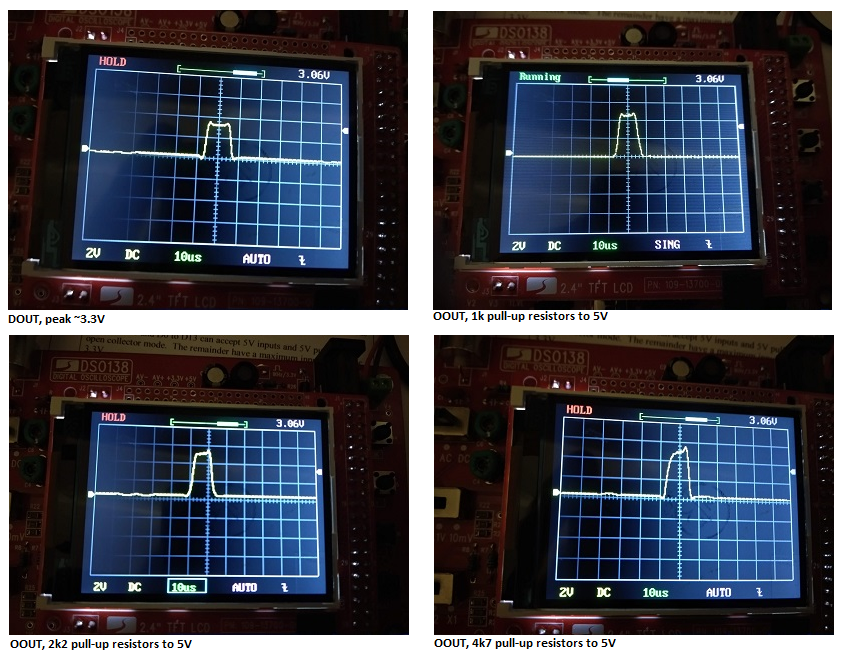 Regards, Tom Game*Mite, CMM2 Welcome Tape, Creaky old text adventures |
||||
| Turbo46 Guru Joined: 24/12/2017 Location: AustraliaPosts: 1593 |
Hi Tom, It seems clear that it is not the pulse length that is the problem. I think you are right and the problem is the rise time of the pulse although all examples of your traces look well withing the 15us rise time and the required logic levels. You don't say where your traces are taken from? They may not be much different at the Maximite end but could be different at the CD4021 end after the capacitance of the cable and that of the input gate has it's effect on the edge of the pulse. I would be checking the cable resistance from the Maximite to the CD4021 including the connector and checking that there is no difference between the 0v at the Maximite and the controller. Or I might just say blow it, 1K works so I'll use 470R just to be sure and leave it at that. Keep Safe Bill Keep safe. Live long and prosper. |
||||
| Turbo46 Guru Joined: 24/12/2017 Location: AustraliaPosts: 1593 |
Hi Tom, When I woke up this morning with your problem on my mind something occurred to me and I had to check this page again. There are NO capacitors on the controller board! It is pretty much standard practice to have an electrolytic or tantalum capacitor to filter the power supply where it enters a board - especially at the end of a cable. Also most circuits will include at least one 100nF monolithic capacitor per IC mounted as close a possible to the IC power supply pins to reduce the effects of switching transients within the IC. The Maximite has 9 of these. I would find a way to add a 10uF or more electrolytic capacitor near where the power supply enters the controller and a 100nF monolithic capacitor to the back of the IC across the supply pins. Being mindful of ESD and short circuits. I wish I could say that would fix your problem but I can't. I know it's working with 1K pullup resistors now but it shouldn't be that critical and the DSO traces don't show why it is. Bill Keep safe. Live long and prosper. |
||||
| thwill Guru Joined: 16/09/2019 Location: United KingdomPosts: 3845 |
Hi Bill, I'm flattered that you are still thinking about my little problem. If I'm understanding you correctly the capacitors you are referring to (at least the 0.1 uF ones) are the despiking/decoupling/bypassing capacitors that Don Lancaster refers to in his TTL and CMOS Cookbooks. Assuming by "controller board" you mean the NES controller board* then I would expect they are already present if required (and perhaps just missing from the referenced article); those Japanese fellows have a reputation for knowing a thing or two about electronics In any case I don't particularly want to "butcher" the controller by trying to fit additional capacitors to it.* The controller I'm actually using is a (Fami)clone and the board just contains some button contact tracks and a single black epoxy blob about 1 cm in diameter. There is no guarantee it actually contains a 4021 (like an original NES) �it may actually be a 74C615 or other functionally equivalent package. Should I have a 10 uF capacitor on my breadboard for the 5V supply from my Maximite? ... or from my linear benchtop power supply? I haven't had the opportunity to poke the signals further. The traces I photographed were measured at the "4021" end ... though the scopes ground was attached near the power supply - would that matter of all the grounds were connected? The scope only has a single probe so I can't measure the clock pulse near the Maximite and near the "4021" simultaneously. I note that in the CMOS Cookbook it says "The rise and fall times on the clock input of clocked blocks must be faster than 5 us. Otherwise, erratic operation caused by clock skew can result." I'm not entirely certain how to interpret that, but the rise time is certainly in the 5 us ballpark. Best wishes, Tom Edited 2020-04-12 08:07 by thwill Game*Mite, CMM2 Welcome Tape, Creaky old text adventures |
||||
| Turbo46 Guru Joined: 24/12/2017 Location: AustraliaPosts: 1593 |
Good evening Tom, It's sad but things like that consume me. Yes those are the 0.1uF capacitors I mean although I don't have the books. There is no visible sign of a capacitor in the pictures of the NES controller board on that site. I have used the 74HC165 for a very similar purpose for a Micromite project and they will run quite happily at 3.3v. This blob must include pullup resistors for the switch inputs then? Maybe it's a custom IC. Yes, a capacitor on the breadboard would be a good idea. I understand your reluctance to "butcher" the board but I would still add the capacitors if there are none visible. They really should be mandatory. Most things these days are made to a price, it may work well for the intended application but as soon as you try something different... Bill PS I'll grudgingly admit that using a pulse may be the quicker method. Keep safe. Live long and prosper. |
||||
Grogster Admin Group Joined: 31/12/2012 Location: New ZealandPosts: 9063 |
I was waiting for someone to mention those things! I have used those once or twice, and they work great for 3v3 pins. Matherp's OC output on 5v pins is fine for 5v pins, but if you don't have any 5v rated pins left and still need to interface bidirectionally between 3v3 and 5v, these little things are just the ticket, and cheap at about $1 each little 4-channel board. Smoke makes things work. When the smoke gets out, it stops! |
||||
| Turbo46 Guru Joined: 24/12/2017 Location: AustraliaPosts: 1593 |
I looked at them when Bill suggested them but they were out of stock and still are. They may be available elsewhere but I didn't look. The trouble with Banggood is their stuff takes sooo looong to arrive. I'd like to known what the chip is too. Bill Keep safe. Live long and prosper. |
||||
| PeterB Guru Joined: 05/02/2015 Location: AustraliaPosts: 639 |
Bill Grogster et al Those level converters use a simple FET in a clever configuration. I will now try to remember the circuit. Peter edit. So I googled FET level converter and circuits popped up. P Edited 2020-04-12 14:07 by PeterB |
||||
| Turbo46 Guru Joined: 24/12/2017 Location: AustraliaPosts: 1593 |
Ah, thanks Peter. I Googled 'FET level shifter' and there are lots of them like this. 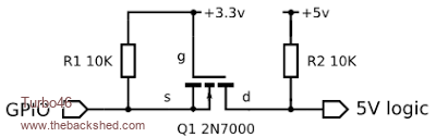 Bill Keep safe. Live long and prosper. |
||||
