
|
|
Forum Index : Microcontroller and PC projects : Feedback from a continuous rotation servo
| Author | Message | ||||
| Volhout Guru Joined: 05/03/2018 Location: NetherlandsPosts: 5931 |
For small robots the movement across the floor is often implemented by stepper motors. These provide an acceptable ammount of torque (to move the robot) and provide position feedback (the number of steps). Alternatively DC motors are used, with optical encoders at motor shaft (often the gearbox output). Bot solutions require additional motor controllers, and position can be determined better than 1 degree of motor shaft angle. For cheap robots in student robot competitions, such as a sumo bot, these solutions are expensive. In these robots continuous rotation servo's are used. Continuous rotation servo's are RC servo's, that normally provide position feedback, that are modified. The position feedback potentiometer is replaced by fixed resistors, the mechanical angle limiters removed. What remains is a motor, gearbox, and motor controller. The motor controller can be controlled by sending a PWM signal (as in RC). But the unit does not provide any feedback signal. This article describes a method I use to implement feedback to the continuous rotation servo, as an elementary method to determine the robots progress and position. This is done using an optical reflection sensor. 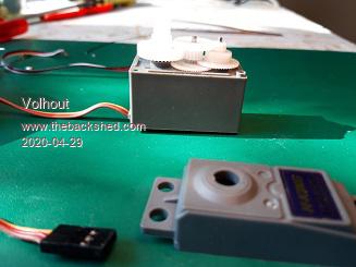 This picture shows a cheap RC servo, when the gearbox is opened. 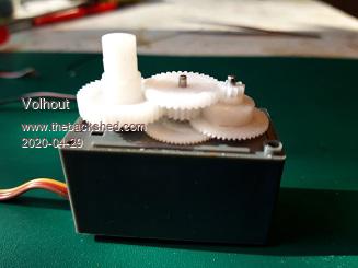 A close up of the gearbox. This gear arrangement is typical for many RC servo's. 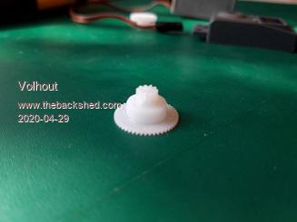 This gear is the one that is key to this implementation. It is dome shaped. 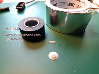 We need these materials of change the gear into an optical encoder wheel. 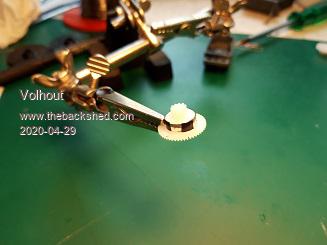 First we put a strip of reflective aluminum tape around the dome, and then apply small pieces of black isolation tape in a regular pattern. I applied 4 at 90 degrees angle, but 8 or 16 can also be done. 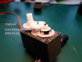 Then we mount the gear back into the gearbox. 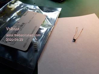 The optical reflection sensor used has a focal distance of 0.5mm. This one is a SMT part, and I had to add wires. There exist similar sensors with pins. That makes life easier. 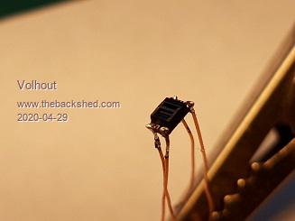 4 wires soldered to the sensor 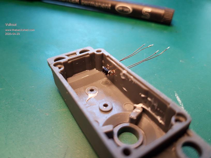 in the gearbox cover 4 small holes (0.8mm) are drilled and the wires are pulled through. The sensor is roughly positioned, but can be moved through the wires. Put the gearbox cover back on and push the wires inward until the sensor touches the dome gear (the encode wheel), mark the position, and pull the wires out 0.5mm. Then apply glue to the wires/housing to fix them. 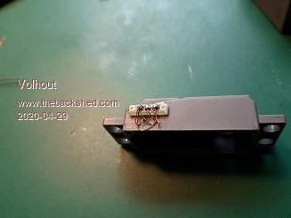 Glue a piece of veroboard to the servo cover as a strain relief, and solder the 4 wires to that. 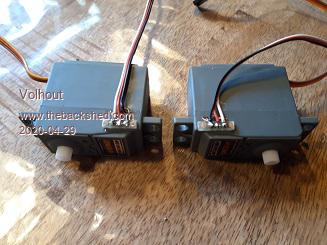 2 servo's modified, note that one is mirrored, so the servo's can be used to drive wheels of a robot without the sensor wires being exposed. The reflection sensor is connected similar of all optical sensors. The LED is continuously drive from 3.3V through a 330 ohm resistor. The sensor has a 220k pullup resistor and directly drive a MX170 pin. The 220k was the best value for this sensor, with this configuration. Maybe this of use to someone. I just wanted to share, just in case someone can make use of it. Volhout PicomiteVGA PETSCII ROBOTS |
||||
mikeb Senior Member Joined: 10/04/2016 Location: AustraliaPosts: 178 |
Where there is a will there is a way. Well done.  Mike B. There are 10 kinds of people in the world. Those that understand binary and those that don't. |
||||
| Paul_L Guru Joined: 03/03/2016 Location: United StatesPosts: 769 |
MAGNIFICENTLY IGENIOUS!!! Rube Goldberg would be proud. Paul in NY |
||||
| The Back Shed's forum code is written, and hosted, in Australia. | © JAQ Software 2026 |
