
|
|
Forum Index : Electronics : aerosharp rewind help
| Page 1 of 2 |
|||||
| Author | Message | ||||
| stockleys Regular Member Joined: 21/06/2019 Location: United KingdomPosts: 54 |
hello good people i hope you are all safe and well in these strange times. i am looking for a little advice if i may. i have read as many posts as i can regarding the ozinverter etc and rewinding the aerosharp transformer. i have acquired a single unit. i cannot get my hands on a second to make a 6kw transformer,. so i have decided i will go with a single. can the original secondary (230v) be left in place and used as is. just rewind the secondary (now primary) if so, what size primary would i need and how many turns for 24v? i am guessing 14 turns and 50mm. (9:1 ration or there abouts. i am hoping i can leave the 230v winding as is. i plan to use the wire from the 250v winding to make my primary just unsure how many in hand i would need to make 50mm. with a sufficiant sized board, could the transformer do short bursts of 4kw? many thanks guys stay safe |
||||
| Warpspeed Guru Joined: 09/08/2007 Location: AustraliaPosts: 4406 |
Yes that is quite possible. To know for certain, connect up the 230v winding to the 230v grid supply, and measure the no load idling power. That will give you a pretty fair idea of how much idling power your inverter will ultimately have. �Something like 20 to 25 watts might be a reasonable expectation for a single toroid. If its much higher, like 30 to 50 watts, add extra turns to bring it down to something you feel more comfortable with. Now if you are using a 24v battery, you need to decide how far you are going to discharge the battery. In other words the MINIMUM dc voltage the inverter will ever see. That might be 20 volts for example, but it will depend on the type of battery chemistry and how hard you plan to punish the battery. Again that is a value judgement, and entirely up to you. Anyhow, suppose you decide 20v battery minimum is your design goal. The best your inverter will ever be able to do is generate a 20v peak voltage across the primary, or 20 x 0.7071 = 14.142 volts rms. So the transformer ratio would need to be 14.142v/230v or roughly 16:1 Now as the number of turns on the existing 230v winding is unknown, try adding a temporary winding as a dummy primary of thin wire, and see how that goes. See how many turns are needed to achieve roughly 14 volts with the toroid powered from 230v grid power. Your guess of 14 turns will probably come pretty close, but do the test anyway to be more certain. Next step is to measure the hole in the toroid and work out the thickest wire that will fit into that space. �Here is a handy calculator: https://www.engineeringtoolbox.com/smaller-circles-in-larger-circle-d_1849.html As flexible fine stranded welding cable can be expensive, try it first with some rope of a convenient size to find out what sort of length you will need to buy. The power rating of just the transformer is limited only by safe temperature rise. At some stage its going to get so hot it fails. But its large and heavy with a very high thermal mass, so short bursts of very high power will be perfectly o/k. Edited 2020-05-27 10:52 by Warpspeed Cheers, �Tony. |
||||
| ryanm Senior Member Joined: 25/09/2015 Location: AustraliaPosts: 191 |
From memory if you look through this huge thread... https://www.thebackshed.com/forum/ViewTopic.php?FID=4&TID=10348 There is a bit of a dicussion half way through about using single cores with the primary still on. Madness even made some special half sized power boards, think he was putting a 4KW nominal rating on them. |
||||
| noneyabussiness Guru Joined: 31/07/2017 Location: AustraliaPosts: 506 |
A suggestion, use the " 250v " winding, add turns to the 230v winding to match the voltage and parallel them.. gives you a little more capacity and loweres idle current... then do as above... I think it works !! |
||||
| stockleys Regular Member Joined: 21/06/2019 Location: United KingdomPosts: 54 |
thanks warpspeed. i have tested the idle current, my grid voltage is 240v i had an idle current of 13.8w �  im guessing thats really good. i ran only 2 turns of secondary 2.5mm wire and got 2.47v (only wire i had to hand as i wasnt planning to do that test tonight. that makes me think i will only need 12 turns of primary to get a little over 14v. with regards to low voltage shutdown. �i was thinking 22v � what would my primary voltage aim be for the voltage? i plan to have a 900ah 24v battery bank. my current inverter (12v 3000w high frequency) has not seen loads over 2.4kw so i suspect it will be rare for this toroidal to see anything more than that. maybe microwave and vacuum cleaner at the same time (guess 3.2kw) Edited 2020-05-28 08:19 by stockleys |
||||
| Warpspeed Guru Joined: 09/08/2007 Location: AustraliaPosts: 4406 |
Great stuff, 13.8 watts magnetizing power is excellent. A bit of extra power will be required to run the circuit board, but the finished inverter should I expect, finally idle at just under one amp dc. Minimum design dc voltage 22v, so a 15.56v ac primary would be the thing to aim for. As you measured 1.235 volts per turn with 240v input, that works out to about 12.6 turns. Twelve turns should work out very nicely. Here are some specifications for good Aussie double insulated orange welding cable: https://www.tycab.com.au/wp-content/uploads/2018/04/Tycab_Power_Brochure_2016_web.pdf Probably 25mm sq rated at 121 amps continuous with 11.8mm outside diameter. But if it will fit, 35mm sq rated at 150 amps continuous with 13.1mm outside diameter ? Cheers, �Tony. |
||||
| stockleys Regular Member Joined: 21/06/2019 Location: United KingdomPosts: 54 |
thanks warpspeed thats great news. im hoping to reuse the wire from the 250v winding. (there is certainly plenty of it) i think i read somewhere that 35 of 1.6mm would equate to roughly 70mm (overkill for my needs) so could i used 18-20 of 1.6mm wires and come up with just over 35mm2 equivalent primary? im confident it will take 12 turns of 35mm |
||||
| Warpspeed Guru Joined: 09/08/2007 Location: AustraliaPosts: 4406 |
1.6mm diameter is equal to 2.0mm square copper area. A typical rating for current density in transformers might be 4 amps per mm squared, so each strand of that 1.6 diameter wire would normally carry about 8 continuous amps. If that wire came from the original 250v winding, that would suggest the transformer may have originally been rated at something like 250v x 8 amps = 2.0Kw at a guess. The primary now needs to be 15v and for 2Kw, that would be 133 amps which may require about 16 strands at 8 amps per strand. Another way of looking at this, would be the turns ratio would be 240v/15v or 16:1. So the voltage ratio is 16:1 and the current ratio also 16:1, therefore the primary needs 16 strands and the secondary 1 strand to have equal copper losses both sides. You may also discover that when you put all that wire back on in the same place, the total length of wire used might work out to be pretty close to being the same as well. Cheers, �Tony. |
||||
| Warpspeed Guru Joined: 09/08/2007 Location: AustraliaPosts: 4406 |
That estimated 2Kw rating would be a conservative commercial rating for running at constant full load 24 hours forever. The toroid is large and heavy, slow to heat up and slow to cool down. I would think it should do 3Kw for half an hour easily without breaking into a sweat. Pretty ideal size for a typical home inverter that will be running very low average power with only the occasional peaks. Sixteen strands would be 32mm squared. Twelve turns of 35mm welding cable will be a lot less work if it will fit. You will probably need to get some of that for the battery cables anyway. Cheers, �Tony. |
||||
| stockleys Regular Member Joined: 21/06/2019 Location: United KingdomPosts: 54 |
The unit the transformer came from was rated for 3kw. The 250v winding was 1.6mm 3 in hand. So 25amps by your reasoning. I was looking to run at 230v Although my mains at the time was 240V, it�s often as low as 230v. (It was late at night when I tested so little load on in the street and our house so less voltage sag) Am I right I�m thinking these transformers are normally 1.6mm 3in hand for the 230v winding? If so, does that still mean a 16:1 ration is needed? |
||||
| Warpspeed Guru Joined: 09/08/2007 Location: AustraliaPosts: 4406 |
Three strands of 1.6 diameter would indeed normally be capable of 24 amps continuous, which seems rather a lot. Ratio will still be 16:1 with the same number of turns. Getting back to design current density in the wire. The higher the current density the hotter the wire will run, but how hot it actually gets depends on the available cooling. A very large transformer will have turns buried very deep below many other layers and will run hotter. A smaller transformer will not suffer so much from the "hot spot" problem. So there are no hard and fast rules, a lot depends on experience and the geometry of the transformer. I have always used 4 amps per mm square and had good results with large toroids. Wikipedia also suggests that as a common design figure. Scroll down to "in practice" https://en.wikipedia.org/wiki/Current_density Now this guy recommends 2.3 amps per mm squared. http://engineerexperiences.com/design-calculations.html In which case 1.6 mm wire (2.0 mm sq) would be rated for 4.6 amps per strand, and three strands 13.8 amps or 3.174 Kw at 230v. The more you search, you will find a lot of variation of what various designers consider appropriate current density for different kinds and sizes of transformer. If you look up 14 gauge in the following Wire table, its the same stuff. 1.6mm diameter, 2.0 mm squared. https://www.powerstream.com/Wire_Size.htm They suggest that 14 gauge wire can carry 32 amps for "chassis wiring" and 5.9 amps for "power transmission" over long distances. So the same wire can have very different current ratings depending on what it is being used for. Cheers, �Tony. |
||||
| stockleys Regular Member Joined: 21/06/2019 Location: United KingdomPosts: 54 |
Ok so based on your own 8amps continues for the 1.6mm wire, I have decided to go with 20 strands of 1.6mm. I have measure enough to do 16 turns plus a 12 inches either end for connection plus another 6 inches for a choke. I calculated that should be 160 amps continuous. Or 3.6kw Does that sound correct? |
||||
| Warpspeed Guru Joined: 09/08/2007 Location: AustraliaPosts: 4406 |
Should work fine. Toroids have a very open exposed winding with a large exposed surface area and fewer layers. That gives much better cooling potential than an E and I type transformer where the steel core encloses much of the winding trapping the heat. So we can be a bit more adventurous with our current density. I have helped quite a few people here with their magnetics design, and there have never been any problems. Cheers, �Tony. |
||||
| stockleys Regular Member Joined: 21/06/2019 Location: United KingdomPosts: 54 |
thankyou. i did a full primary test today with 14 turns with 232v in, i got 14.9v tomorrow, i will start winding the new primary. just trying to find a pcb that will handle 4kw at 24v that will fit inside the aerosharp case alongside the toroid. i like the look of madness's 12 fet board, would that do 4kw at 24v? |
||||
| Warpspeed Guru Joined: 09/08/2007 Location: AustraliaPosts: 4406 |
Just remember that 4Kw at 24v will need to run at similar peak current as 8Kw at 48v. That will require a lot of mosfets and very large heatsinks. Cheers, �Tony. |
||||
| brucedownunder2 Guru Joined: 14/09/2005 Location: AustraliaPosts: 1548 |
Doing well there stocky... Here's a pic of my rewound Torodial, with 25mm Aussie earth wire. It's the hard drawn copper 7strand stuff that is very stiff on the fingers to wind to the tight corners. I think I managed 31 turns on the Inspire core, would not try it again . I'd go multi strand ,like welding cable or many strands of enallemed transformer wire. Mine is 48 volt, I think I ended up with around 20 something watts idle. 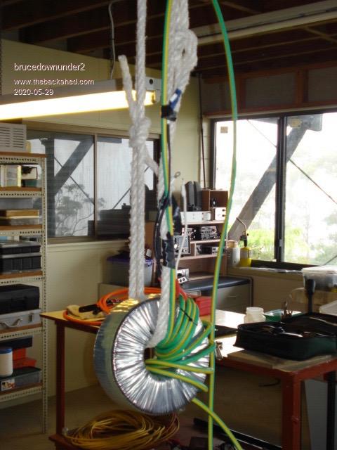 Bushboy |
||||
| Warpspeed Guru Joined: 09/08/2007 Location: AustraliaPosts: 4406 |
Yes you need a good setup for winding toroids.  Cheers, �Tony. |
||||
| brucedownunder2 Guru Joined: 14/09/2005 Location: AustraliaPosts: 1548 |
Stocky. and Tony,plus others,, I gutted an inspire case ,, but decided it was going to be too tight a fit for the Inspire Toroidal wound tranny ,pictured above. I had to gut a Erisson 20Amp charger case ,lucky I had. I was going to position the Torodial alongside the Inspire case, but decided to keep all the works within the one case. Probably a good decision ,because of the switches, fuses,Choke,Caps and AC ,DC wiring will really bulk up the insides.. I'll fit meters, switches,Etc on a top front panel designed fro this stuff. Getting there, long slog ,but I love doing this stuff. Bottom pic is the latest(Ericsson case) Bruce 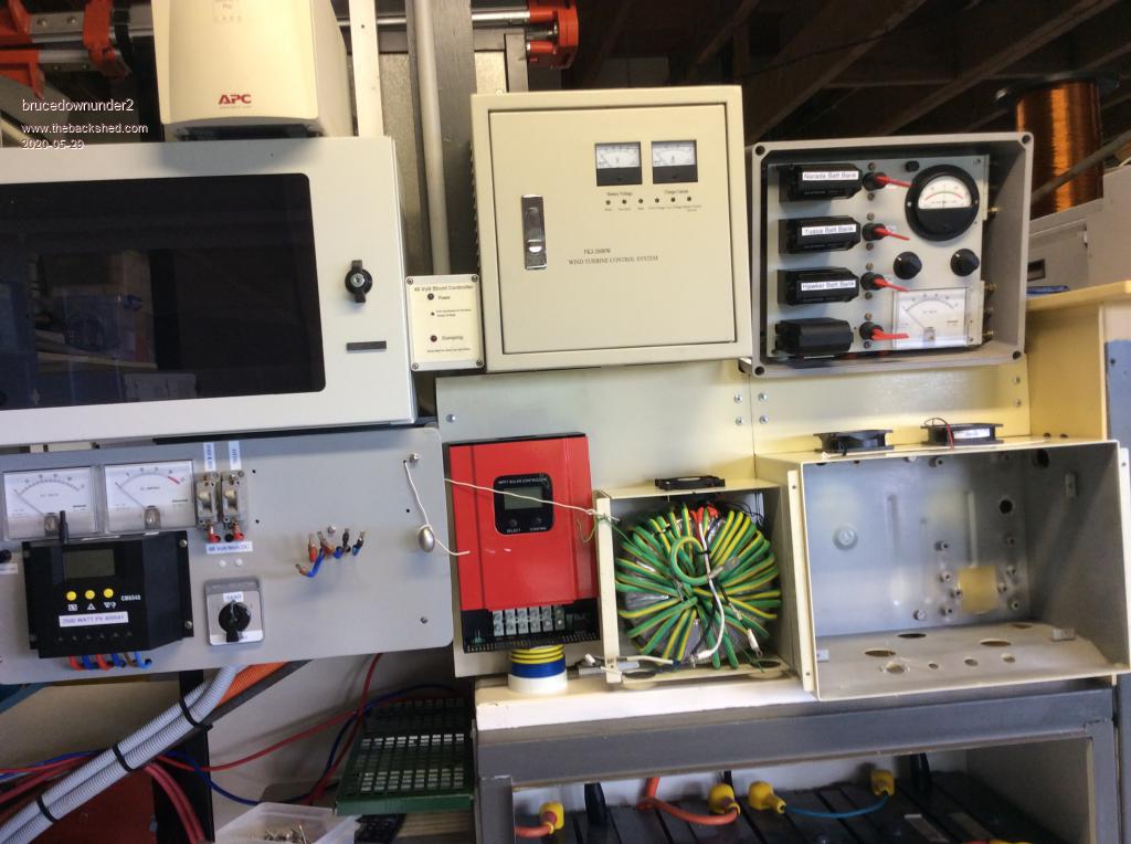 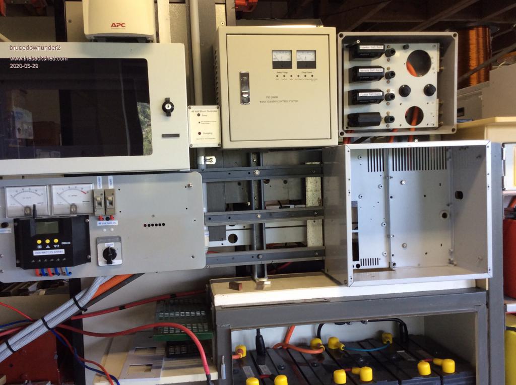 Bushboy |
||||
| stockleys Regular Member Joined: 21/06/2019 Location: United KingdomPosts: 54 |
can anyone point me in the direction of where i can download the gerbers for either a nanoverter or a madverter? i have searched and search, cannot find. also, with either of these board, is it possible to use them at 24v? thankyou. |
||||
renewableMark Guru Joined: 09/12/2017 Location: AustraliaPosts: 1678 |
Madness designed his power and control boards and he sells them direct. He hasn't made the gerbers public. It's his design and he figures he should profit from his design work...... fair enough. They don't cost a fortune, so buying a proven design is smart. The nanoverter was a collaboration and is open to the public. Poida may have a spare board. Just did a quick search, I couldn't find the gerbers, someone will point you to them, they are on here somewhere. Cheers Caveman Mark Off grid eastern Melb |
||||
| Page 1 of 2 |
|||||
