
|
|
Forum Index : Microcontroller and PC projects : Any ideas about limiting inrush current starting BIG ac motors?
| Page 1 of 3 |
|||||
| Author | Message | ||||
| Paul_L Guru Joined: 03/03/2016 Location: United StatesPosts: 769 |
Starting freon compressors from a local generator is a pain. I have a 6 KW 240 volt compressor here which draws a running current of 26A but has an inrush current of 144A. It works fine from the power company main, but it trips my natural gas powered 10KW generator. Hyper Engineering in North Wollongong makes a soft starter which triggers a Triac for an increasing percentage of each succeeding mains half cycle until it gets the motor up to speed, then it pulls in a mechanical relay. Has anyone down under ever run into a Hyper Engineering soft starter and do you know anything about this gadget? I wonder if there would be any way to have a microcontroller running MMbasic trigger a Triac appropriately. I suspect that, with a 60Hz line frequency, a first attempt might be to switch on the Triac for 10 ms at the end of the first half cycle, then increase the on time by 10 ms for each subsequent half cycle. This would reach a 100% on state of the Triac after 100 half cycles or about 833 ms. after which a mechanical relay could be energized. Does this sound doable? The first problem would be to precisely detect the zero crossing point of the line voltage. An opto-coupler would definitely be a good idea. Paul in NY |
||||
| PeterB Guru Joined: 05/02/2015 Location: AustraliaPosts: 669 |
G'Day Paul Those things are sold in the US and Canada so the first question is, "why roll your own when you can buy one?" Having said that, to detect a zero crossing you can use a low voltage transformer and a comparator (LM311?) to produce a nice square wave with a suitable amplitude. This square wave then drives a unijunction to generate a delayed pulse. Well it worked for a model train controller. Good luck. Peter |
||||
palcal Guru Joined: 12/10/2011 Location: AustraliaPosts: 2039 |
This is a link to a soft start for a Kelvinator 6kW air conditioner. Soft Start "It is better to be ignorant and ask a stupid question than to be plain Stupid and not ask at all" |
||||
| SimpleSafeName Guru Joined: 28/07/2019 Location: United StatesPosts: 351 |
Never having used Hyper Engineering products, I can't speak to them. But soft starters have been around for a very long time, and the better ones do as you describe, use what essentially is a VFD to bring the motor up to speed, drop out the VFD while connecting the motor across the mains. The not as good ones are simply a VFD without the ability to change the speed. They bring up the motor to speed and continue to run the motor off of the VFD. This obviously wastes power. Can you start your compressor using a Wye-Delta starter? https://www.youtube.com/watch?v=h89TTwlNnpY |
||||
| Paul_L Guru Joined: 03/03/2016 Location: United StatesPosts: 769 |
@Peter --> Emerson buys them and puts their own Copeland brand on them, but they charge $320 US. The step down transformer driving a comparator is an obvious way of detecting the zero crossing point. An opto-coupler might also work where the zero crossing point is when the lights are out. @Paul (the other one) --> $329 is a pretty good deterrent to the Kelvinator part. @John --> My compressor is single phase, Wye-Delta is not applicable. I think the way to go is with a variable time domain cycle slicer with a mechanical relay when it is up to speed. Thanks guys. Paul in NY (the other other Paul). |
||||
| zeitfest Guru Joined: 31/07/2019 Location: AustraliaPosts: 683 |
just an idea - use a tank to "store" low-pressure and connect it to the compressor outlet at switch-on. The low pressure will make the compressor run as a "vacuum engine" for a moment and get it rotating while the electrics can merge in. When it is running the tank can connect back to the low-pressure side to "recharge" instead. (various valves etc needed). That would also help for hot-weather starting.. probably impractical, it would take a fairly large tank/cost I guess. |
||||
| robert.rozee Guru Joined: 31/12/2012 Location: New ZealandPosts: 2528 |
a soft-starter is probably the best way to go, i worked for a company that developed and built them (aucom electronics) 10+ years ago, testing the firmware. a starting current of 6x to 8x the running current is pretty typical for an AC electric motor, with no sensible means of reliably getting around this in a non-electronic way. is the motor single, 2, or 3 phase? there was mention of a VFD earlier. while technically 'nicer', they are a whole lot more complicated than a soft-starter, and generate pretty nasty electrical noise that is injected back down the power lines. in north canterbury (here in nz) VFDs are a bit of a headache for the electricity suppliers due to the electrical hash they inject into the grid. think of 5000+ VFDs over the district running half the time! as i recall, VFDs are not so easy to bypass with a relay, requiring to be carefully locked to the mains prior to the relay closing. hence most VFDs simply remain online permanently. soft-starters - essentially a large light dimmer with a bypass relay - are far simpler, and once bypassed quite benign. in the scale of things, your motor is extremely small, and a soft-starter for it will be very cheap. as a bonus, using a soft-starter will also extend the service life of both motor and the attached pump due to eliminating mechanical the 'bang' of a DOL start. have a look here for more info: https://www.aucom.com/home cheers, rob :-) |
||||
| LouisG Senior Member Joined: 19/03/2016 Location: AustraliaPosts: 130 |
Paul, Sometimes lo-tech is the way to go. Use old fashioned resistance starting. Surprise, surprise, it is still modern. Experiment by putting a single resistance in series with the motor calculated to drop the voltage to say 2/3 or half on starting. Then short-circuit it with a hand switch. Might have to experiment a bit. You could then substitute a relay for the hand switch. Worth a try. If you do, let us know how it went (either way). Louis - |
||||
| palcal Guru Joined: 12/10/2011 Location: AustraliaPosts: 2039 |
I used the resistance idea on a much smaller scale to start a fridge running off an inverter. The resistance does not have to be in circuit very long, just long enough to saturate the windings. I used a resistance with the relay contacts wired across it, the time the relay took to pull in was long enough. "It is better to be ignorant and ask a stupid question than to be plain Stupid and not ask at all" |
||||
| CaptainBoing Guru Joined: 07/09/2016 Location: United KingdomPosts: 2171 |
Other shedders look like they have this covered and would have more specific experience in this stuff but I just wanted to throw this out there: http://www.fruitoftheshed.com/Circuit%20Ideas.Really-Simple-Zero-Crossing-Detect.ashx I have used this circuit in speed controllers which used variable cycle duty cycle (they weren't great but it wasn't this ZTC circuit's fault). From here it was a piece of cake to get a uC to measure the cycle time and then provide the decreasing delay you are after. I used assembly in a PIC, a stock mm Mk2 might struggle to give you the precision but a MM+ @120MHz clock or MMX @250 should handle this and I would go that way if I was doing it again. Once you have the triac & hand-off relay hardware all working nicely, it's just software to determine the ideal starting sequence. Would be a good practical project. |
||||
| lizby Guru Joined: 17/05/2016 Location: United StatesPosts: 3784 |
Can you provide a circuit diagram? PicoMite, Armmite F4, SensorKits, MMBasic Hardware, Games, etc. on FOTS |
||||
| zeitfest Guru Joined: 31/07/2019 Location: AustraliaPosts: 683 |
A compressor hot start is going to take a lot of power to get moving no matter what. ĀA soft start device connected to mains power will no doubt soften the power draw but it still has to power the compressor start load. So I am wondering if it is connected using the generator, will the generator have the surge capacity or maybe still trip at the required power even with a resistance starter. Is there an unload valve on the compressor for starting (?) ed- I can remember some old rule-of-thumb advice, for starting compressors the generator needed to be 2.5x or 3x the continuous load rating. That was with older tech but it was from people who used and depended on the stuff working. Edited 2020-06-13 22:53 by zeitfest |
||||
| SimpleSafeName Guru Joined: 28/07/2019 Location: United StatesPosts: 351 |
@John --> My compressor is single phase, Wye-Delta is not applicable. I think the way to go is with a variable time domain cycle slicer with a mechanical relay when it is up to speed. Ah, bummer. I wondered... I'm going to up vote the resistance starting plan then. Wouldn't a potential relay work in this application to short out the inline resistance? It's the same device that would be used in a phase inverter to drop out the starting caps. About $10 for the relay. But there are a ton of ZCD circuits firing Triacs and SCRs out there, way too much to list. This guy has a series on the subject: https://www.youtube.com/user/murkava/search?query=zero |
||||
| LouisG Senior Member Joined: 19/03/2016 Location: AustraliaPosts: 130 |
Hi Paul, It's me again. Resistance starting and triac/SCR starting have one thing in common: Motor current = supply source current (due to the series connection). Both starting techniques primarily are meant for softening the starting torque of the motor but are not ideal methods for reducing loading on a limited supply source. The ultimate way to reduce supply source loading is auto-transformer starting. The supply current will then be less than the motor current when starting. e.g. Assume a 110V to 12V @ 20A transformer with separate windings. Energise the primary with 110VAC and feed your motor with 110V in series with the 12V secondary connected in anti-phase. This will reduce the motor voltage to 98V for starting, then switch the transformer out of circuit. Don't worry too much about overloading the transformer, it will only operate for a second. You might need a transformer with a somewhat higher voltage secondary for even less loading of the supply source. Louis - |
||||
| Paul_L Guru Joined: 03/03/2016 Location: United StatesPosts: 769 |
@rob --> The aukey website you linked to offered to send me a pdf explaining how they start motors. The resultant downloaded file was zero length. There's something wrong with their website. The compressor is a Copeland scroll type, 240 v, 60 Hz, single phase, locked rotor 144 A, running 26 A, running 6240 W. The scroll is an ingenious positive displacement compressor which starts with very little torque required. The visualization of the scroll action is difficult -- it's one of those gadgets where you're not quite sure that it will actually work. These animations show it running. https://www.youtube.com/watch?v=dsabYhhOko0 https://www.youtube.com/watch?v=yNgqI4XPUZc Due to the power level I don't think the resistor idea is practical. It would have to cut the voltage from 240v to 80v to reduce the current from 144A to below 50A which would cause the resistor to dissipate 160v x 50A or 8000W for a few seconds. That sounds more like a welder application than sort start. The same problem would exist using a bucking transformer or an auto-transformer. @Andrew --> The optically coupled zero crossing detector circuit you reference is the first part of the problem ... pinning down the exact time of the zero crossing. In the states we have a center tapped secondary in the utility pole transformer where the center tap is grounded. It might be more accurate to use a high value resistive divider to reduce the 240 v to 3 v and then use a comparator to find the zero crossing point. Assuming I want a repeatability of +/- 0.1 ms in the turn on pulse and that it will take up to 110 clock cyles to process an MMBasic timer comparison then the uP clock period would have to be below .1mS/110 = 0.9 uS or a minimum frequency of 1.1 MHz which seems to be really sloooow. Am I doing something wrong with the math? Paul in NY |
||||
| CaptainBoing Guru Joined: 07/09/2016 Location: United KingdomPosts: 2171 |
yes I see your point. I don't like the voltage divider thing, dips in the power would affect it, it would be huge input impedance to your sense circuit and you have no protection from surges. In practice that pulse you see on the scope is governed by the VF (or at least the behavior) of the LEDs in the optocoupler. As soon as the LED starts to burn, the transistor will begin to conduct. Any jitter (of which I never saw any) is entirely down to the frequency of the mains. In practice, if you put a comparator or precision schmitt (probably using an op-amp) so you pick up the low voltages at the start of that quite slow leading edge of that pulse, you would maximise the time available to do your work and I think you'll easily get your precision - even at 1MHz, 0.1mS is a fairly useful chunk of processor time. In my instance it was a 4MHz PIC and it was so predictable I polled for it - not even an interrupt. Suck it and see, what's to lose? An amusing afternoon with the breadboard |
||||
| palcal Guru Joined: 12/10/2011 Location: AustraliaPosts: 2039 |
@ Lizby A very rough diagram 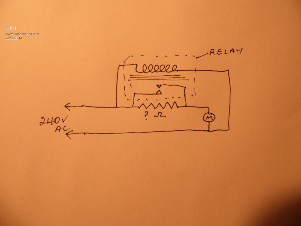 Sorry about the size. The resistor has to be chosen to suit the supply, so if you have 5 amps available you could use say 50 ohms. The wattage has to be large but not the calculated wattage as it is only in circuit for a fraction of a second. As I said I used it on a small scale to run a fridge that only drew .8 amps but still overloaded my generator on start. The resistor only has to be in circuit until the back EMF is generated by the collapsing magnetic field in the motor winding. In Paul L's case he would need a fair lump of a resistor, and it probably would not be possible. Delaying the relay for maybe a second would also help. "It is better to be ignorant and ask a stupid question than to be plain Stupid and not ask at all" |
||||
TassyJim Guru Joined: 07/08/2011 Location: AustraliaPosts: 6538 |
I used to use good old fashioned light bulbs when I wanted a current limiter. Still do for suspicious power supplies I want to test. You will need a few kW and then their inrush current might be too much. Jim VK7JH MMedit |
||||
| zeitfest Guru Joined: 31/07/2019 Location: AustraliaPosts: 683 |
Assuming the question is about starting a motor instead. I guess it is a capacitor-start motor (?), the rest follows on from that. |
||||
| lizby Guru Joined: 17/05/2016 Location: United StatesPosts: 3784 |
Here's proof of concept for an AC "cycle slicing" process using a PICAXE 08M2 and an ebay/amazon/aliexpress zero-crossing + triac control module: AC dimmer module 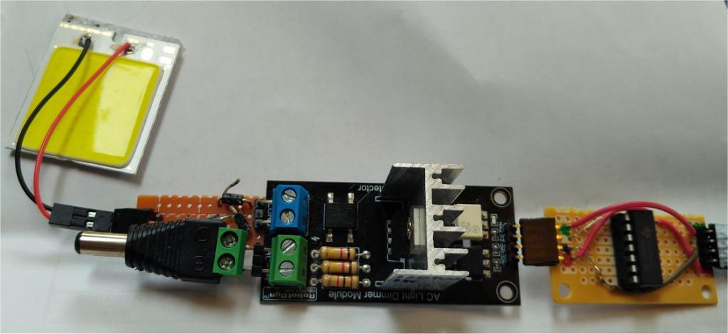 Ā Mains frequency here in North America is 60Hz, so there are 120 zero crossings (for half cycles) per second. This means that each half cycle is 8.33ms, so time-slicing after the zero-crossing detection has to be within that time frame. I happened to have an old 12V AC wall plug transformer, which made testing safe and easy. It turned out the module detected zero-crossing with no problem using that transformer. I found what appears to be the circuit diagram for the module here: https://www.instructables.com/id/Arduino-controlled-light-dimmer-The-circuit 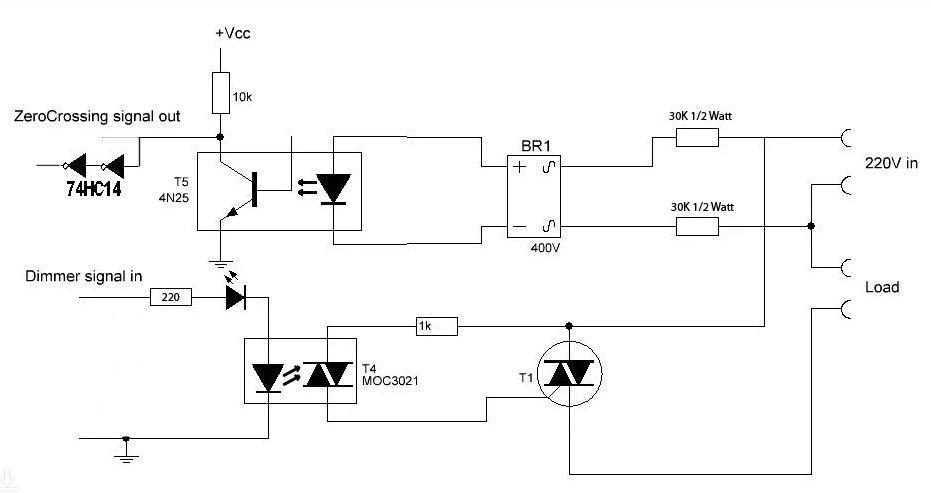 (I added the two gates on a 74HC14 schmidt trigger inverter to sharpen the zero-crossing signal.) For the PICAXE, I set the frequency at 16mHz instead of the typical 4mHz. This means that the PAUSE 1 command which normally pauses for 1ms actually pauses for 312us. Increasing to PAUSE 2 adds 250uS; the same for additional pause times. So I started with a pause just short of the 8.33ms after zero-crossing, and then fired the triac. I reduced the pause time after a certain number of half-cycles--32 half-cycles with the same pause and 26 250us steps gave me about 4 seconds to ramp up to nearly full on (at which point with a big motor, you would switch on a relay or SSR to provide full current). Here is what it looks like on my PC scope, DPScopeSE, the on-time ramped at each zero-crossing; the zero-crossing trigger is blue, and the on-time is red. 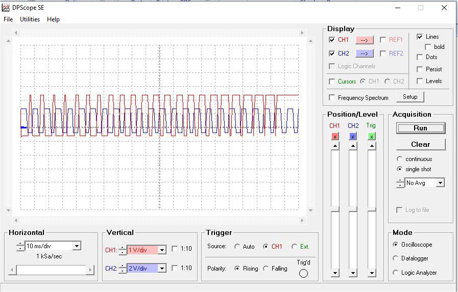 Here's the code with the approximately 4-second ramp. ' 08ZeroCrossFire.bas #terminal 19200 '#terminal 9600 '#terminal 4800 #no_data symbol pauseTime=b1 ' from 32 to 1; at 16mHz, 8ms to ~ 250uS symbol i=b2 ' FOR loop counter symbol pFire=C.4 symbol PAUSEMAX=26 ' was 31--too long symbol NREPEATS=32 ' 15 for 2-second ramp setfreq m16 'setfreq m8 pause 2000 pauseTime=PAUSEMAX high pFire pause 4000 low pFire pause 4000 do Ādo: loop until pinC.3=0 ' Āpause pausetime ' debounce Ādo: loop until pinC.3=1 Ālow pFire Āpause pauseTime Āhigh pFire Āinc i Āif i > NREPEATS then Ā Āi = 0 Ā Ādec pauseTime Ā Āif pauseTime = 0 then Ā Ā Ālow pFire Ā Ā Āpause 8000 ' 2 seconds on low Ā Ā Āhigh pFire Ā Ā Āpause 8000 ' 2 seconds on high Ā Ā Ālow pFire Ā Ā Āpause 8000 ' 2 seconds on low Ā Ā ĀpauseTime=PAUSEMAX Ā Āendif Āendif loop I added a full wave bridge to the output of the module, and put on a 12V LED as load. The brightness ramps up over 4 seconds (though it's not dramatic). With a DVM attached the reading rises from 0V to 16V. Here's a youtube video Edited 2020-06-15 01:52 by lizby PicoMite, Armmite F4, SensorKits, MMBasic Hardware, Games, etc. on FOTS |
||||
| Page 1 of 3 |
|||||
| The Back Shed's forum code is written, and hosted, in Australia. | © JAQ Software 2026 |
