
|
|
Forum Index : Microcontroller and PC projects : Interesting CMM1 Problem
| Author | Message | ||||
Chopperp Guru Joined: 03/01/2018 Location: AustraliaPosts: 1126 |
Hi, Just had an interesting fault with my CMM1 some of you may be interested in. My CMM1 runs 24/7 taking some reading etc & graphs some of them among other things. For a while now, one of my temperature readings was misbehaving every now & then & slowly getting worse. Quite recently I noticed the CMM was resetting itself & that started to become more frequent. The other day I decided to look at the data that gets stored to the SD card to see if that would reveal anything. I have a bank of 5 switches which uses an ADC input to determine which one is pressed. I pressed the one to disable SD card writes & removed the card. I did think that I did press the correct switch but while transferring the SD data to my PC, I noticed that the CMM had stopped with the protest message saying that it couldn't find the SD card. Bugger, I thought. (I know I can have an ON ERROR SKIP line in my program, but I haven't). I then checked some recorded data & found the the CMM had been resetting quite frequently. Not good. I reinserted the SD card & pressed the switch again to tell the CMM that the card was inserted, but the wrong switch was registered. After some ginning around, I eventually checked the voltage feeding the switches & found it was about 3.8V. Should have been about 3.3V. I then checked the main 3.3V regulator & it's output was also reading 3.8V. No wonder the CMM was getting upset. My immediate thought was that the 3.3V Reg was playing up. I had a quick scrounge & found another one on an old board & removed it. I was part way through removing the suspect one on the CMM board when I thought that the problem was more likely to be either the 5V or I/P volts getting onto the 3.3V line somewhere. I removed the Reg anyway & it tested OK on the bench. I refitted it but the problem still persisted. Another Cap across the output didn't make any difference & I couldn't see anything obvious on the 3.3V line with my cheap DSO either. I have an Arduino prototyping shield plugged into the main board with a couple of ribbon cables going of to other stuff. I disconnected everything at the end of the cables from the shield as well as the main cable from the rear I/O socket, but the problem of a high 3.3V still remained. I then removed the shield itself & the regulator returned to it's nominal 3V3. So it appeared that there was a fault on the shield somewhere. I had a good look but could not find it. Isolating either the 5V or the 3.3V feeds to the shield returned things to normal. (I bent the long connecting pins up out of the way). I eventually settled for just leaving the 5V pin isolated to the shield & temporarily re-routing the 5V required for the other stuff. The CMM was much happier & the original temperature reading problem settled down. Ran OK for hours with no obvious problems. The next day, I happened to find the other different prototyping shield I knew I had somewhere & took the plunge and wired that one to the ribbon cables up & plugged it in (including connecting the 5V). All worked as normal including the switches. The CMM has been running fine for the past day or so with no problems. I have yet to go back & fully check out the original shield to see if I can fathom what was going on. Most likely, poor wiring somewhere. Good to see the CMM working again as it should. Brian ChopperP |
||||
| CaptainBoing Guru Joined: 07/09/2016 Location: United KingdomPosts: 2171 |
I am glad it survived! Close call. Keen to hear the outcome of the investigation on that shield Edited 2020-06-14 06:24 by CaptainBoing |
||||
| Chopperp Guru Joined: 03/01/2018 Location: AustraliaPosts: 1126 |
Hi CaptainBoing I'm glad too. Could have let some of that magic smoke out. Then again with some of my wiring & not too delicate handling of my setup, I'm surprised it's lasted as long as it has. Will advise once I get around to checking the shield out again. Brian ChopperP |
||||
TassyJim Guru Joined: 07/08/2011 Location: AustraliaPosts: 6538 |
What you describe looks like one of the non-5V tolerant pins was getting 5V and the protection diodes working overtime. Jim VK7JH MMedit |
||||
| Chopperp Guru Joined: 03/01/2018 Location: AustraliaPosts: 1126 |
Hi Jim, Yes, the voltage of around 3.8V on the 3.3V supply would suggest this but I couldn't find where the 5V was getting in to the 3.3V TBC Brian ChopperP |
||||
| Chopperp Guru Joined: 03/01/2018 Location: AustraliaPosts: 1126 |
OK, found the problem. One of the ribbon cable wires I had soldered to the I/O pin pads was just touching the 5V bus running past the row of pads (A3 pin). Must have melted too much insulation when I soldered it on. Measured about 3-2 ohms when tested today but would have been intermittent etc depending on how much downwards pressure was on the cable. Would have been like that for a good few years. (I cut the ribbon cables, leaving them attached to the offending shield when I reconnected them up the other shield. They were a bit too long anyway & needed tidying up. I used terminal blocks this time around) Brian. ChopperP |
||||
| Chopperp Guru Joined: 03/01/2018 Location: AustraliaPosts: 1126 |
FYI The green covered wire in the foreground was the offender. The row of holes behind the cable are 5V 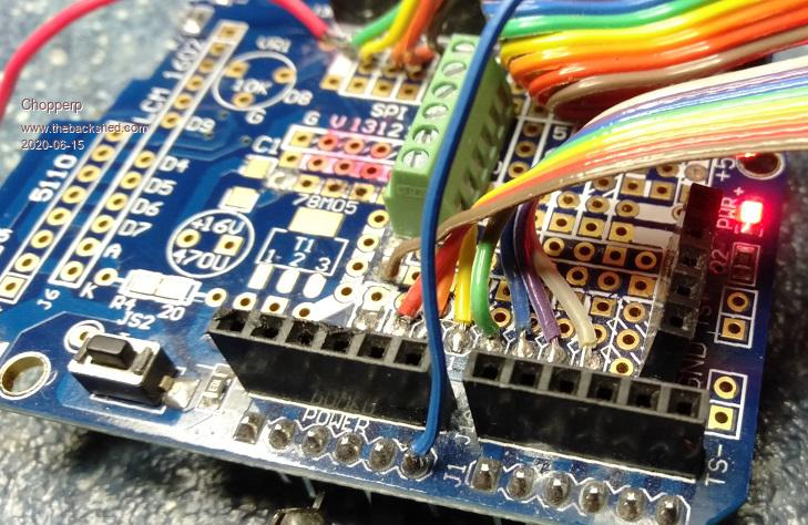 Brian ChopperP |
||||
| The Back Shed's forum code is written, and hosted, in Australia. | © JAQ Software 2026 |
