
|
|
Forum Index : Microcontroller and PC projects : What is "CN:" as a signal level?
| Author | Message | ||||
Grogster Admin Group Joined: 31/12/2012 Location: New ZealandPosts: 9975 |
I am playing around with my RF signal meter, but the manual does not elaborate at all on what any of the signal levels returned actually mean: 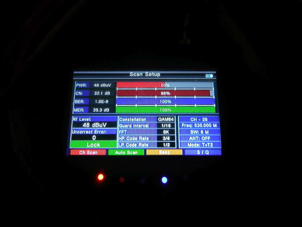 PWR is POWER, or, essentially signal-strength. BER is Bit-Error-Ratio. MER is Modulation-Error-Ratio. What is CN? ...and don't say "China"!  If it was "SN:" I would think it was Signal-Noise ratio, but "CN"..... Channel-Noise? ...but that could not be right, as 96% noise on that channel would surely be something you would not want!  Smoke makes things work. When the smoke gets out, it stops! |
||||
| Turbo46 Guru Joined: 24/12/2017 Location: AustraliaPosts: 1693 |
I found 'Carrier to Noise' level. Bill Keep safe. Live long and prosper. |
||||
TassyJim Guru Joined: 07/08/2011 Location: AustraliaPosts: 6538 |
Usually called NM - Noise margin 'Margin' is the important bit. More the merrier. Jim VK7JH MMedit |
||||
| Grogster Admin Group Joined: 31/12/2012 Location: New ZealandPosts: 9975 |
Thanks, chums.  @ Jim - so are you saying that MORE in that percentage level, is a GOOD thing? IE: lower is bad as with the other levels? Smoke makes things work. When the smoke gets out, it stops! |
||||
| Volhout Guru Joined: 05/03/2018 Location: NetherlandsPosts: 5931 |
Hi Grogster, CN or C/N means carrier to noise. It is a measure of the signal quality (how much usefull signal is there peaking out of the backgound noise). The C/N is measured when the transmitter output is a continuous wave (in most cases that means they switch of the carrier modulation). If you have a measurement device that shows C/N and you have no access to the transmitter to switch off the modulation, the C/N is a integral of all transmitter power in the channel bandwidth divided by the total noise power in the channel bandwidth. In digital modulation the demodulator and descrambler chip does this calculation for you based on raw ADC samples and their clouds mapped on the IQ diagram. Advantage is that you don't need any extra hardware to do this, disadvantage is that you get absolute nonsense as long as the demodulator is not locked. For the device you have this technique is most likely used. This implies that the best method of aligning a antenna or dish is to start azimuth and elevation alignment by peaking the signal level (don't look at C/N yet). Once the antenna has the right azimuth and elevation, you optimize the C/N by keeping the antenna aligned at the transmitter, but rotating it around the beam axis to find the tuning for horizontal or vertical modulation. This is achieved when best suppression of the opposite polarity is achieved, and can only bee seen in the C/N, not in the signal strength. If you have an antenna this means rotating the actual antenna. If it is a dish, you optimize by rotating the feedhorn or LNB. Good luck... Volhout Edited 2020-06-21 05:14 by Volhout PicomiteVGA PETSCII ROBOTS |
||||
| Grogster Admin Group Joined: 31/12/2012 Location: New ZealandPosts: 9975 |
Thanks - excellent description. I knew what PWR, BER and MER were, but not CN, so this has cleared it up in my head beautifully. Smoke makes things work. When the smoke gets out, it stops! |
||||
| The Back Shed's forum code is written, and hosted, in Australia. | © JAQ Software 2026 |
