
|
|
Forum Index : Microcontroller and PC projects : MM+: Tearing my hair out. LCD woes....
| Page 1 of 2 |
|||||
| Author | Message | ||||
Grogster Admin Group Joined: 31/12/2012 Location: New ZealandPosts: 9975 |
Hi all. I'll get straight to the point. 64-pin MM+ chip driving an SSD1963 5" LCD panel. First controller board works fine with 2x 5" and 1x 7" LCD modules. Second controller board(exactly the same board) does not. - Checked and re-flowed all the PIC32 pins in case I did something wrong there. - Repeatedly have OPTION LCDPANEL DISABLE, then re-enable. - Both board have the same version of MMBASIC. - Both boards test as 100% on all pins to the LCD(see below). - Pulled some hair out and start fit of swearing. - Tried slowing the CPU to 30MHz. - Tried GUI RESET LCDPANEL after power-up. - Tried different power-supply. - Pulled out more hair. - Posted this thread. As I say, both boards are identical, so that can't be the problem. The LCD just flatly refuses to initialise on the 2nd board, but works fine on the 1st board. Thinking that perhaps I had dicky connections on the controller-to-LCD module side of things, I plugged the 2nd board into my E100/E64 port tester thing I built a while back to test just this very thing. ALL pins to LCD bus are 100% intact and where they should be, all 8 data-bit LED's light in sequence, all control lines(RST,RD,WR,RS) work 100%. Tester code for the 64-pin chip connected to 1963 LCD module: Dim BUS%(12)=(00,60,61,62,63,64,01,02,03,28,08,24,27) For X=1 To 12 SetPin(BUS%(X)),DOUT Next Do For X=1 To 12 Pin(BUS%(X))=1 Pause 250 Pin(BUS%(X))=0 Pause 250 Next Loop Until Inkey$<>"" End This code lights D0-D7 in sequence, and all LED's light, so all 8 bits are there. This code lights all the control lines in sequence, so they are all there too. LCD CS line is connected permanently to ground. LCD RD line is connected to pin-8, even though I am not using the read feature. Setup command is: OPTION LCDPANEL SSD1963_5,L,,8 LCD never initialises. BACKLIGHT command has no effect. Now, pull off board #2, and plug in board #1 - remember: this is the exact same board design - switch on, and everything works as expected on the same LCD. Try another 5" LCD on #1 - works fine. Try a 7" LCD on #1 - works fine. Plug #2 into 5" LCD #1 - does not work. Plug #2 into 5" LCD #2 - does not work. Plug #2 into 7" LCD #1 - does not work. Next, I plugged in #1(the board that IS working) to the port-tested LED board thing, and loaded and ran the code above, and, as expected, all the LED's sequence exactly as they should. Remove #1 from the LED port tester thing, plug in #2, run the same code - everything looks good, all LED's sequence exactly as they should - identical to board #1. Plug #2 back into an LCD - nothing. A this point, I have no hair left, and you would not believe how hard it was for me to NOT fill this post with the swearing I am now doing.   Does anyone have any idea what the %@&!^^@*@(( could possibly be going on here. I am completely stumped, have tried everything I can think of, all tests indicate it should be working, but it won't - but only on the 2nd board. I think I will build a 3rd board and try that. About the only thing I can think of at this point, is that the PIC32 is actually faulty, but LED testing disagrees with that, cos it is saying all the pins are there and accounted for.....    Smoke makes things work. When the smoke gets out, it stops! |
||||
| matherp Guru Joined: 11/12/2012 Location: United KingdomPosts: 11512 |
Faulty power. Power rail collapsing when LCD starts to take juice |
||||
| Grogster Admin Group Joined: 31/12/2012 Location: New ZealandPosts: 9975 |
OK, but how come it works just fine with the 1st board and not the 2nd? If it was PSU(and I have tried another one), would you not see the same issue on board #1? (the one that IS working) So confused..... EDIT: Here is an image of my controller board: 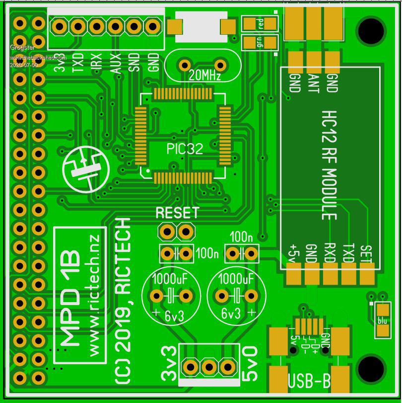 Note that I have 1000uF 6v3 caps on the 3v3 and 5v supplies, which should surely be able to deal with any start-up current when the board tries to initialise the LCD.... EDIT AGAIN: I'm going to bed. 2:10AM here, and if I play with this anymore now, I will probably go insane. I will try yet another PSU type tomorrow and see if that does indeed help.  Edited 2020-07-09 00:09 by Grogster Smoke makes things work. When the smoke gets out, it stops! |
||||
| Turbo46 Guru Joined: 24/12/2017 Location: AustraliaPosts: 1693 |
Maybe a faulty (high resistance) plated through in the power circuit? Can you check for voltage drop? Bill Keep safe. Live long and prosper. |
||||
| PeterB Guru Joined: 05/02/2015 Location: AustraliaPosts: 669 |
Good morning Grogster. A very simple trick is use a stiff nylon brush with great vigor on both sides of the board to remove any microscopic bridges. Of course you may have done this already in which case, ignore the above and it has to be Bill's plate through hole or a faulty soldered joint or it's just not your day  . . Good luck. Peter |
||||
| Grogster Admin Group Joined: 31/12/2012 Location: New ZealandPosts: 9975 |
Thanks for the suggestions everyone, and now a new day has arrived, I slept surprisingly well after such a late night swearing and scratching what remained of my hair, trying to work out why it would not work. I will indeed try one more PSU just to be sure there, but if I am going to build another one, I think I will re-design the controller board, so that the PSU is local and linear. I never had this problem with the E100, which used a linear PSU for the 3v3(LM3940), so there must indeed be something strange going on here. If I move the PSU to the controller board, and make it SLIGHTLY bigger to accommodate a 7805 feeding a 3940 for the 5v and 3v3 rails, then I can feed the board with one single supply. The only reason the current board has 3v3 & 5v input from an external supply, is that I wanted to keep the PCB to 50x50, but I could make it slightly larger, fit in linear PSU stages, and not have it cost any more to get made, and it will still be small enough to be self-supporting on the 40-pin LCD connector. I will still post back with the results of using another PSU later. Smoke makes things work. When the smoke gets out, it stops! |
||||
| Volhout Guru Joined: 05/03/2018 Location: NetherlandsPosts: 5931 |
Hi Grogster, Some things to look at: - The quality and location of the 10uF-47uF ceramic cap. - The crystal, is it the right one. Maybe the oscillator is on the edge of running, and therefore has phase noise -> PLL's inside the PIC32 may not lock reliable. You can check this by changing the capacitors at the crystal to lower values (i.e. 10pF), or try a canned oscillator. - The chip itself, I remember that there are 2 speed grades, and have read somewhere that some chips where marked wrong. Maybe you are running at too high clock. - Ripple on the +3.3V. Good luck, Volhout PicomiteVGA PETSCII ROBOTS |
||||
| Grogster Admin Group Joined: 31/12/2012 Location: New ZealandPosts: 9975 |
Thanks for the suggestions. 10uF cap is X5R type, and sourced from Element-14, so not cheap rubbish.  Crystals are TXC brand from Element-14 or Mouser, so also not cheap eBay stuff there. Yes, there are 100MHz and 120MHz parts for the MM+ chips. I am using 100MHz ones, but the firmware(MMBASIC) starts up on the MM+ at 100MHz by default, so there SHOULD be no problems there. SHOULD be.... Ripple could indeed be an issue as I am using external SM buck-converters for the 3v3 and 5v rails. What confuses me, is that the 1st board works, which suggest that the PSU cannot be a problem, or it would not work either. Anyhoo, I have redesigned the board, making it 15mm longer, and incorporating good 'ole linear regulator stages: 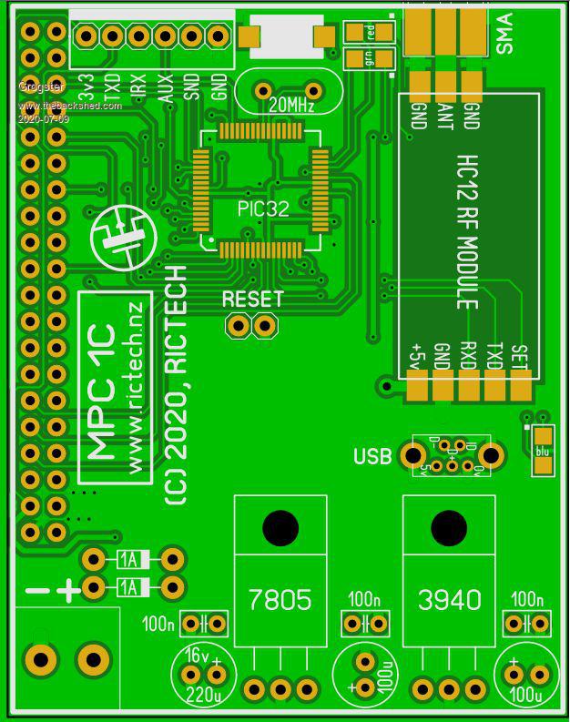 The large 'Green' area around these regs, is copper GP/pour, to act as a form of heatsink. I plan to feed this from a single 9v supply capable of a few amps at least. This will mean that the 7805 will dissipate about 1.19W of heat, which should be fine using the copper as the heatsink. 9v - 0.6v(diodes) - 5v = 3.4v, * 0.35A total load = 1.19W of heat. If I used 12v input, dissipation of 7805 would increase to 2.24W, or 2.87W @ 13.8v input from a battery-backed PSU unit, which is PROBABLY what I will use. This is still well within the dissipation of the 7805, albeit getting a bit on the hot side. 5W is about as far as I would be prepared to push it. I can also add stick-on heatsinks for extra dissipation, but I guess I will need to run a few tests with this arrangement and see how hot she gets! Smoke makes things work. When the smoke gets out, it stops! |
||||
| Volhout Guru Joined: 05/03/2018 Location: NetherlandsPosts: 5931 |
Hi Grogster, If heat becomes an issue, you can replace the 7805 with a switching one. 7805 switching regulator The ripple at 5V (powering the 3940 and the backlight LED) is not crucial. The parts has the same 7805 pinout, but is slightly wider, you may have to move your 220uF cap and 100uF cap a bit to accomodate it. Volhout PicomiteVGA PETSCII ROBOTS |
||||
| Turbo46 Guru Joined: 24/12/2017 Location: AustraliaPosts: 1693 |
Shouldn't you find out what the problem is with the other board first? Just in case the new one has the same problem. Bill Keep safe. Live long and prosper. |
||||
| Grogster Admin Group Joined: 31/12/2012 Location: New ZealandPosts: 9975 |
@ Volhout: Thanks for the link to that little thing! Never seen them before. Shame they can only output 500mA though, but I will look through the list, as they might have ones that can do an amp or so.@ Turbo46: YES, and you are quite right. I am still playing with the old board, but I have a feeling something in the PSU is the problem, as all the tests I have done to date(see post #1) suggest everything is fine. Confusing. I have not ordered the new design or anything yet, I just posted an image of what I have rustled up so far. However, I am going to hook up two separate lab supplies this afternoon, bypassing my buck-converters and see if it springs to life then. I don't hold out much hope, but I will at least try. Perhaps the buck-converters are introducing lots of HF ripple which might be upsetting something. Sometimes with high-speed digital stuff, it can be hard to beat the good old linear stage!  Smoke makes things work. When the smoke gets out, it stops! |
||||
bigmik Guru Joined: 20/06/2011 Location: AustraliaPosts: 2981 |
Grogs, Just a thought.. My first thought is power supplies, but another though I had was to set up a simple timing loop speed test both boards and make sure that both boards are running at the same speed. There could be some issue that is related to the crystal.. Have you got your HC12 soldered on? Remove it and try again. It is very close to the CPU. Kind Regards Mick Mick's uMite Stuff can be found >>> HERE (Kindly hosted by Dontronics) <<< |
||||
| bigmik Guru Joined: 20/06/2011 Location: AustraliaPosts: 2981 |
Hi Grogs, Make sure you dont have a solder mask where the regs will contact to get a good thermal connection. Kind Regards Mick Mick's uMite Stuff can be found >>> HERE (Kindly hosted by Dontronics) <<< |
||||
| Grogster Admin Group Joined: 31/12/2012 Location: New ZealandPosts: 9975 |
Hey Mick. Just finished trying two separate lab supplies to feed in the 3v3 and 5v, and the 2nd board still refuses to initialise the LCD, so there is some kind of weird issue going on with this board. I will do the timing loop thing - good idea. I will post results. The HC12 is on-board, but does nothing yet, cos I can't get the LCD to operate, so it won't be radiating any kind of RF, so that can't be the problem, as also, board #1 has its HC12 in place, and it works fine. Re: solder-mask, yes, good idea. If I end up building the new board design, I will alter the solder-mask to get good thermal connection there. Smoke makes things work. When the smoke gets out, it stops! |
||||
| PeterB Guru Joined: 05/02/2015 Location: AustraliaPosts: 669 |
G'Day All Following on from Mick's comment about the proximity of the HC12. Is it possible that #1 works but is marginal and #2 is too marginal? How about turning the rails up and down to test for this? Just my 2 bobs worth Peter edit. You just about beat me to it but did you crank the volts ap and down? P Edited 2020-07-10 12:54 by PeterB |
||||
OA47 Guru Joined: 11/04/2012 Location: AustraliaPosts: 1050 |
Just my 2 cents worth, have you checked the vias on the faulty board? OA47 |
||||
| Grogster Admin Group Joined: 31/12/2012 Location: New ZealandPosts: 9975 |
#1 test: 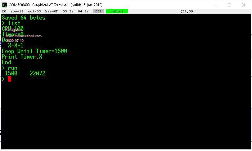 #2 test: 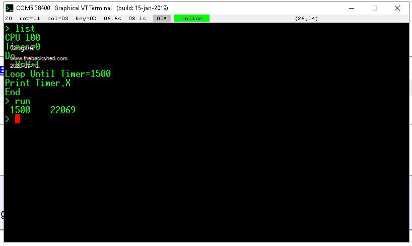 There is only 3 counts between them (22072 vs 22069), so they seem to be smack-on timing wise. I guess I would need to do multiple tests and compare the results for true accuracy. @ PeterB: No, I did not twiddle the voltages up and down. I will try that, and see. I will try 2.8-3.5 for 3v3, and 4.8-5.2 for 5v. Smoke makes things work. When the smoke gets out, it stops! |
||||
| Grogster Admin Group Joined: 31/12/2012 Location: New ZealandPosts: 9975 |
Not SPECIFICALLY, but I did do the LED testing, and that certainly shows that all the connections are present and accounted for. The LED testing won't show high-resistance vias though, so I will do some probing around just to see if there is anything odd going on there. You never know, but out of all the PCB's I have had made(hundreds and hundreds now), I have only EVER had ONE board that had ONE via that was bad. Not saying bad vias could not be the issue, but I think it would be extremely unlikely. Still, I will do some probing as I said. Smoke makes things work. When the smoke gets out, it stops! |
||||
| Grogster Admin Group Joined: 31/12/2012 Location: New ZealandPosts: 9975 |
UPDATE: Found out what was going on here, but first a little pretext. I built the new version of the board, and low and behold - it did not work either!!!!  By this point, I was thoroughly convinced I MUST have done something wrong in the layout, simply cos I could take the LCD's that would NOT work on the new PCB, and plonk them on an E100, and they spring immediately to life. That proves that the LCD module itself is not the issue, and it has to be something on my PCB layout that I have done wrong.  All data and control lines are 100% intact, and exactly where they should be, so the head-scratching begins - 'Why the hell won't it work then?!?!!!' I say to myself at 2AM...... Finally tracked it down to the LCD CS pin NOT being grounded. It WAS connected to the surrounding ground-plane, and it did show as connected to ground when I tested the connection in the layout software, but it was on the outer edge of the PCB, and when they slice them up in the factory, that cut off the connection to the ground-plane. "I think the phrase rhymes with clucking bell." - Blackadder. So, what all this means, is that the original one that had the external buck-converter power supply for 3v3 and 5v was just fine - I resurrected it, and put a link wire on the LCD CS to a 'Real' ground, and it springs to life every single time. Funny that..... I guess what threw me, was that SOMETIMES it would initialise on one of the LCD's, but not the other one, yet BOTH of them worked fine on an E100 board. Just luck that sometimes that one LCD would respond I guess, and probably interesting that it did at all, with CS floating.(cos technically, it should not) The good old linear 7805 was still getting too hot in this application on the new PCB anyway, so I will go back to the external supply idea. I note that in this issue of Silicon Chip magazine, they feature a tiny 78xx buck-converter regulator as a drop-in replacement for the 78xx series. The specs are quite good for a switcher on this module, albeit with more ripple then a linear(C'est La Vie), but the ripple on these is still quite low, so might have to make a few of those to try them out. But, I digress..... Anyhoo, I post this so everyone can have a bit of a chuckle at my expense, being the instrument of my own problems, but also to illustrate that even if you churn out hundreds of different PCB designs, you can still get subtle things like this wrong from time to time!  Smoke makes things work. When the smoke gets out, it stops! |
||||
Chopperp Guru Joined: 03/01/2018 Location: AustraliaPosts: 1126 |
Quote Anyhoo, I post this so everyone can have a bit of a chuckle at my expense, being the instrument of my own problems, but also to illustrate that even if you churn out hundreds of different PCB designs, you can still get subtle things like this wrong from time to time! I'm just impressed with all the ones you do produce. No mean feat. ChopperP |
||||
| Page 1 of 2 |
|||||
| The Back Shed's forum code is written, and hosted, in Australia. | © JAQ Software 2026 |
