
|
|
Forum Index : Microcontroller and PC projects : CMM2: DS18B20 Temp sensor problem
| Author | Message | ||||
| Amnesie Guru Joined: 30/06/2020 Location: GermanyPosts: 639 |
Hi Volhout, good idea, just tried it - no success. I also tried a similar attempt: I connected another of my ds18b20 on pin 24 (BUS) from there a 4,7k to 5Volts and the other pin to GND - this is the way I am used to connect the sensor with my other projects on the atmega328p, but: no success again. I measured the voltage again on the 1-wire BUS with your 22k suggestions: it was now at 3,2 to 3,3 volts. With my attempt, it was at 3,3 volts on the 1-wire-BUS and as I said 5v at the Vdd (accordingly to your picture). I don't know whats going wrong... I checked all my three sensors again with my other little BASIC computer, based on atmega328.. and yes they are still working. ??? no idea... Greetings Daniel Edited 2020-07-15 07:09 by Amnesie |
||||
| matherp Guru Joined: 11/12/2012 Location: United KingdomPosts: 10240 |
just to be pedantic run the following: option milliseconds on do pause 1000 print time$ loop is the time incrementing by 1 second +/- 2 mSec? |
||||
| Amnesie Guru Joined: 30/06/2020 Location: GermanyPosts: 639 |
Here it is... 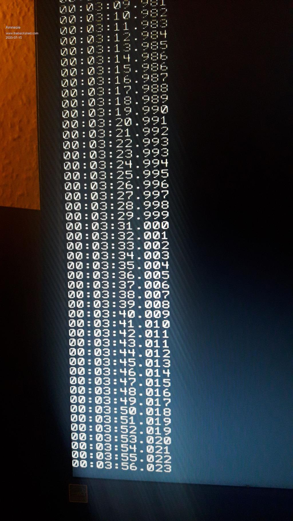 |
||||
TassyJim Guru Joined: 07/08/2011 Location: AustraliaPosts: 6269 |
Your timing looks good so that is not the problem. Can you confirm that you are operating in external power mode. Using three wires as in fig 5 of Volhout's post Jim edit: I just changed mine over to parasitic power but it still works 100% of the time Edited 2020-07-15 08:45 by TassyJim VK7JH MMedit |
||||
| Amnesie Guru Joined: 30/06/2020 Location: GermanyPosts: 639 |
Hi Jim, I am using the external power mode. Tried it with 3.3V supply and with 5v supply (external on breadboard with a 4,7kohm to 1-wire-bus) |
||||
| Volhout Guru Joined: 05/03/2018 Location: NetherlandsPosts: 5058 |
Hi Amnesie, Just to be sure.... You are connecting to a single DS18B20, correct? Not a chain of 3? Volhout Edit: it must be something digital. Otherwise you would never get exactly 1000. It is like this '1000' is some form of error message or default when the CMM cannot resolve the message from the DS18B20. Or when the DS18B20 is still busy....and you are trying to communicate with it too early for it's chosen resolution (9/10/11/12 bit).. Edited 2020-07-15 16:59 by Volhout PicomiteVGA PETSCII ROBOTS |
||||
| TassyJim Guru Joined: 07/08/2011 Location: AustraliaPosts: 6269 |
1000 is the error value. It is what you get returned if no device is present. Amnesie, Can you try this program. It was written before we had the builtin TEMPR function and might be easier to find the problem. I have made a couple of changes to allow it to run on the CMM2 You may have to change the PinNbr if you are not using the pin 42. Ā'1WDS1820.BAS Ā Ā 29 March 2012 Ā'By Ian Delaney Ā ĀPinNbr = 42 Ā ĀGetTemp PinNbr, Temp, pow$, dev$, code$ ĀPrint "The temperature is:" format$(Temp,"% 1.3f"); " degrees C" Āprint dev$;code$;pow$ Ā Ā'''''''''''''''''''''''''''''''''''''''''''''''''''''''''''' Ā' Subroutine to get the temperature from a Dallas DS18B20/DS18S22 Ā' Ā Āor DSS20/DS1820 externally or parasite powered via 1-wire protocol. Ā' Reports temperature, device family, ROM Code and Power connection. Ā' Only 1 device allowed on the cable. Ā' Ā Ā Ā Ā Ā Ā Ā Ā Ā Ā Ā Ā Ā Ā Ā Ā Ā Ā Ā Ā Ā Ā Ā Ā Iandaus Ā'''''''''''''''''''''''''''''''''''''''''''''''''''''''''''' Ā Sub GetTemp (PinNbr, Value,pow$,dev$, code$) ĀLocal T1, T2, t, a1,a2,a3,a4,a5,a6,a7,a8, device, presence, power ĀLocal Countrem, T1C, TConv, T1t, T1t16, Value12, a,b,c,d,e,f,g,h Ā ĀTconv=750 Ā Ā'max time mS for temp conversion in parasite mode Ā' for slowest device Ā Ā'''''''''''''''''''''''''''''' Ā' Ā Check a device is present Ā'''''''''''''''''''''''''''''' ĀONEWIRE RESET PinNbr Āpresence Ā= mm.onewire Ā Ā Ā Ā Ā Ā' reset Āprint "MM.ONEWIRE ";presence Āif presence = 0 then Ā Ā Ā Ā Ā Ā Ā Ā Ā' no device Ā Ātemp = 999.99 Ā Ādev$ = "No device found!" Ā Ācode$ = "" Ā Āpow$ = "" Ā Āexit sub Āendif Ā Ā'''''''''''''''''''''''''''''''''''''''''''''' Ā' Ā check whether power external or parasitic Ā'''''''''''''''''''''''''''''''''''''''''''''' ĀONEWIRE RESET PinNbr ĀONEWIRE Write PinNbr, 1,2,&hcc, &hb4 ĀONEWIRE Read PinNbr,4,1,power Āif power = 1 then Ā Āpow$ = " using External Power." Āelse Ā Āpow$ = " using Parasitic Power." Āendif Ā Ā'''''''''''''''''''''''''''''''''''''''''''''''''''''''''''''''' Ā' Ā get ROM Code - useful if you want more than 1 device on wire Ā'''''''''''''''''''''''''''''''''''''''''''''''''''''''''''''''' ĀONEWIRE Write PinNbr,1,1,&h33 'read ROM code ĀONEWIRE Read PinNbr,0,8,a1,a2,a3,a4,a5,a6,a7,a8 Ācode$ = " with ROM Code "+ hex$(a1,2)+" "+hex$(a2,2)+" "+hex$(a3,2)+" "+hex$(a4,2)+" " Ācode$ = code$ + hex$(a5,2)+" "+hex$(a6,2)+" "+hex$(a7,2)+" "+hex$(a8,2) Ā Ā'''''''''''''''''''''''''''''''''''''''''''''' Ā' Ā determine device family from code Ā'''''''''''''''''''''''''''''''''''''''''''''' Āif a1=16 then Ā Ādev$ = "on DS1820/DS18S20" Āelseif a1=34 then Ā Ādev$ = "on DS18S22" Āelseif a1=40 then Ā Ādev$ = "on DS18B20" Āelse Ā Ādev$ = "Not known" Āendif Ā Ā'''''''''''''''''''''''''''''''''''''''''''''' Ā' Ā read temperature Ā'''''''''''''''''''''''''''''''''''''''''''''' ĀONEWIRE reset PinNbr Ā Ā Ā Ā Ā Ā Ā Ā Ā Ā Ā Ā' reset before command (or use flag=9) ĀONEWIRE Write PinNbr, 8, 2, &hcc, &h44 Ā Ā Ā' start conversion Ā Ā'read external when bit goes hi, for parasitic just wait ĀIf power = 0 Then Ā ĀPause Tconv ĀElse Ā Āt = Timer Ā ĀDo Ā Ā ĀIf Timer - t > 1000 Then Error "Sensor not responding" Ā Ā ĀOnewire Read PinNbr, 4 , 1 , b Ā Ā Ā Ā Ā Ā' conversion done? Ā ĀLoop Until b = 1 print "Conversion time: ";timer-t ĀEndIf Ā Ā'read temperature from scratchpad and convert to degrees C + or - ĀONEWIRE Write PinNbr, 1, 2, &hcc, &hbe Ā Ā Ā' command read data ĀONEWIRE Read PinNbr, 2, 2, T1, T2 Ā Ā Ā Ā Ā ' get the data ĀONEWIRE Reset PinNbr Ā Ā'''''''''''''''''''''''''''''''''''''''''''''' Ā' Ā calculate temp depending on device in use Ā'''''''''''''''''''''''''''''''''''''''''''''' Ā'Need to analyse type of chip to calculate temp from T1 and T2 Ā'T2 is MSB containing sign, T1 is LSB Āif a1=34 or a1=40 then Ā Ā Ā Ā Ā'DS18S22 or DS18B20 is 12 bit Ā ĀIf T2 And &b1000 Then Ā Ā Ā 'negative temp Ā Ā Ā'make 2s complement (1s complement+1) Ā Ā ĀT2 = (T2 xor &b11111111) Ā Ā ĀT1 = (T1 xor &b11111111)+1 Ā Ā Āif T1=1 then T2=T2+1 Ā Ā Ā Ā'add the carry if required Ā Ā ĀValue = ((T2 And &b111) * 256 + T1) / 16 Ā Ā ĀValue = -Value Ā Āelse Ā Ā Ā Ā Ā Ā Ā Ā Ā Ā Ā Ā Ā Ā'positive temp Ā Ā ĀValue = ((T2 And &b111) * 256 + T1) / 16 Ā Āendif Āelseif a1=16 then Ā Ā Ā Ā Ā Ā Ā Ā Ā 'DS18S20 or DS1820 is 9bit or calc to 12bit Ā Āif T2 AND &b10000000 then Ā Ā Ā 'if MSB of T2=1 then negative Ā Ā Ā'Read 12bit resolution and adjust Ā Ā Ā'read scratchpad using matchrom to get Count Remaining @byte 7 Ā Ā ĀONEWIRE Write PinNbr,1,9,&h55,a1,a2,a3,a4,a5,a6,a7,a8 Ā'read from scratchpad Ā Ā ĀONEWIRE Write PinNbr,0,1,&hbe Ā Ā ĀONEWIRE Read PinNbr,0,8,a,b,c,d,e,f,g,h Ā Ā ĀCOUNTREM=g Ā Ā Ā'truncate 0.5deg value (or use integer division \) Ā Ā ĀT1t = T1 AND &b11111110 Ā Ā ĀT1t=T1t / 2 Ā Ā Ā Ā Ā Ā Ā Ā Ā 'make whole degrees Ā Ā Ā'add compensation values read from scratchpad Ā Ā ĀT1t16=T1t*16 Ā Ā Ā Ā Ā Ā Ā Ā Ā'make lsb 1/16 degree Ā Ā ĀValue12 = T1t16 -4 +(16 - COUNTREM) Ā Ā'add 12 bit value Ā Ā Ā'take 2s complement Ā Ā ĀT1C = (Value12 XOR &b11111111111) + 1 Ā Ā ĀValue = T1C/16 Ā Ā Ā Ā Ā Ā Ā Ā'make decimal value in degrees Ā Ā ĀValue = -Value Ā Āelse Ā Ā Ā Ā Ā Ā Ā Ā Ā Ā Ā Ā Ā Ā Ā'positive temp Ā Ā ĀValue = T1 / 2 Ā Ā Ā Ā Ā Ā Ā Ā'9bit value Ā Ā Ā'Read 12bit resolution and adjust Ā Ā Ā'read scratchpad using matchrom Ā Ā ĀONEWIRE Write PinNbr,1,9,&h55,a1,a2,a3,a4,a5,a6,a7,a8 Ā'read from scratchpad Ā Ā ĀONEWIRE Write PinNbr,0,1,&hbe Ā Ā ĀONEWIRE Read PinNbr,0,8,a,b,c,d,e,f,g,h Ā Ā ĀCOUNTREM=g Ā Ā ĀT1t = T1 AND &b11111110 Ā Ā Ā'truncate 0.5deg(or use integer division \) Ā Ā ĀValue = T1t/2 Ā Ā ĀValue = Value - 0.25 + (16 - COUNTREM) /16 Ā '12 bit value Ā Āendif Āendif End Sub My system with the DS18B20 configures for parasitic power gives: MM.ONEWIRE Ā1 The temperature is: 21.000 degrees C on DS18B20 with ROM Code 28 CA A0 F2 05 00 00 3E using Parasitic Power. > Jim edit fixed bug in code Edited 2020-07-15 18:08 by TassyJim VK7JH MMedit |
||||
| Amnesie Guru Joined: 30/06/2020 Location: GermanyPosts: 639 |
Hi, thank you Jim for the help, my ds18b20 is reacting every time different. On the image you can see all kinds of errors. :( I attached my ds18b20 libarary, which works for all my sensors on the atmega328p below (maybe anyone can spot a difference?) @ Volhout, no I am using just one ds18b20 at a time. I am used to this sensors from my atmega328 projects, so at least, I know how to work with them on the atmega328p (there all three work). I just mention three because I have got all the tested individualy with the maximite. None of the works all the time. On the image, you can see 3 different "states" / possible readings (I don't know how to call it), over the time, all those redings are repeating in a coincitential sequence. I took a picture, so you can see all three Āpossible readings. It is interesting, that with this program, the temperature isn't correct (if it has found the sensor). -16,062░C? Also the ROM Code appears to be whether FF FF FF ... or 28 5C BA 56 ..... Now 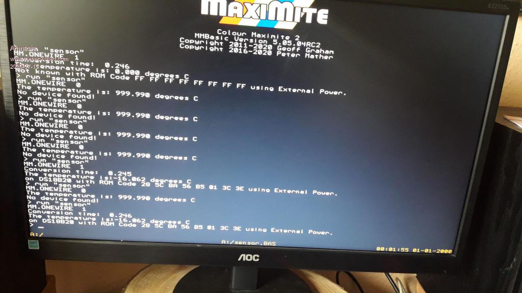 With this library for my atmega328 all three sensors work! Just in case you can see some differences... Edited 2020-07-15 20:09 by Amnesie |
||||
| TassyJim Guru Joined: 07/08/2011 Location: AustraliaPosts: 6269 |
The conversion time should be about 600mS. It looks like the data being returned is very unreliable. Do you have a CRO that you can monitor the data line with? Can you change it to parasitic power and try again. That way the program waits 750mS rather than interrogate the device while waiting for the conversion to finish. Jim VK7JH MMedit |
||||
| Amnesie Guru Joined: 30/06/2020 Location: GermanyPosts: 639 |
I have attached a library to my other post, but somehow it dosn't work and I again can not edit my earlier post.. So another try. With this libarary, all my three snsors work on the atmega328. @ Jim, what do you mean by CRO? Never heard that before. cathode ray ocilloscope? The only words, which make sense to me :) Sadly I have got no oscilloscope around me. ds18b20.zip Edited 2020-07-15 20:15 by Amnesie |
||||
| Amnesie Guru Joined: 30/06/2020 Location: GermanyPosts: 639 |
In parasitic mode I get not one single correct reading at all! 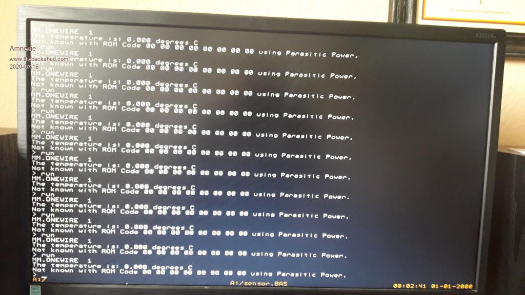 |
||||
| TassyJim Guru Joined: 07/08/2011 Location: AustraliaPosts: 6269 |
No Oscilloscope... We will have to see if we can make the CMM2 into one. But not tonight. I will think about it and do some experiments tomorrow. I really do want to see what is happening on those data lines. Jim VK7JH MMedit |
||||
| Amnesie Guru Joined: 30/06/2020 Location: GermanyPosts: 639 |
Hi Jim, pretty impressive, to make the CMM2 into an oscilloscope. Sooner or later I will buy one, as prices are falling with every year. |
||||
| Poppy Guru Joined: 25/07/2019 Location: GermanyPosts: 486 |
The Forum software still sucks in some ways and ate up my reply. I just want to point on my last in case of need. And if you make the CMM2 an Oscilloscope just also make it a new topic for being separately interesting!   Andre ... such a GURU? Andre ... such a GURU? | ||||
Chopperp Guru Joined: 03/01/2018 Location: AustraliaPosts: 1095 |
Hi Jim, I assume this code can be modified to run more than one device per cable if you know the ROM addresses? Brian ChopperP |
||||
| robert.rozee Guru Joined: 31/12/2012 Location: New ZealandPosts: 2437 |
arduinos generally run the micro at 5v, whereas micromites and maximites are generally operated at 3v3. i wonder if it could be that all your DS18B20 devices are 'clones' and only operate reliably with everything at 5v. try hooking the DATA pin of the DS18B20 to a 5v tolerant pin (3, 5, 11, etc) on the CMM2, and run both the 4k7 pullup and the Vdd pin of the DS18B20 to 5v (pin 2 or 4 on the 40-pin connector). cheers, rob :-) |
||||
| Chopperp Guru Joined: 03/01/2018 Location: AustraliaPosts: 1095 |
Gizmo has mentioned a few times that longish replies are probably best done in a text editor then copied into the reply box. Copying your message to the clip board every few lines as you go would also work as you could paste it back again if lost. ChopperP |
||||
| Amnesie Guru Joined: 30/06/2020 Location: GermanyPosts: 639 |
@ Andre Thank you, but I have ordered now original Dallas 18b20 sensors in germany. The point is; my sensors do 100% work, I checked all three of them with my other BASIC computer which is bulilt up on an atmega328p and all of them are working without a single problem or miss-reading. That is why it might help, if I post the ds18b20 library I am using with them? Would be interesting, if there is a different approach in "my" library than in the maximite one - although I am sure that Peter doesn't used a premade library, instead coded it all by himself. I am curious whether my just ordered original ds18b20 will work... Just in case anybody is interested, with this library, all my sensors do work: ds18b20.zip @ Rob I posted this in an earlier post, done that before. This was my assumption, too. But doesn't work. Edited 2020-07-15 23:08 by Amnesie |
||||
| bigfix Senior Member Joined: 20/02/2014 Location: AustriaPosts: 129 |
Not sure if this was posted already : Github Doc: Your DS18B20 temperature sensor is likely a fake, counterfeit, clone... Github DS18B20 Clones Here you see the flavors and different behaviours and some hints how to ident Maybe somebody will write a certification test program ? |
||||
| Amnesie Guru Joined: 30/06/2020 Location: GermanyPosts: 639 |
I just tested whether my ds18b20 is a fake or not with the suggested test methods via my atmega328p RESULT as expected: Ā But what I still not understand: why does the sensor work with my atmega328p? There must be something different in the maximite firmware than in the library I used. The obvious fact, that on my atmega328, the sensors run @ 5Volts can not be the problem, because I tried it with the maximite, too. But as I said: I ordered a original ds18b20 here in germany at a licenced distributor. And will reply the results! Nevertheless it would be cool, if the maximite would even run with counterfeits, since (according to this link Andre & bigfix posted) nerly every sensor @ ebay is a fake one! Edited 2020-07-16 00:00 by Amnesie |
||||
| The Back Shed's forum code is written, and hosted, in Australia. | © JAQ Software 2025 |
