
|
|
Forum Index : Electronics : Turning a Toyota Prius into a "portable" generator
| Author | Message | ||||
| Warpspeed Guru Joined: 09/08/2007 Location: AustraliaPosts: 4406 |
The analog to digital converter chip is the dual slope integrating type. While its actually measuring the incoming dc, that charges up the integrating capacitor during the measurement period. That should (?) give excellent noise immunity to any high frequency or pulse type noise on the main incoming dc. Have a look with an oscilloscope, it would take a lot of noise on the main incoming dc supply to cause a problem. All those huge electrolytics right across the main dc supply on your main circuit board should be quite effective. Cheers, ĀTony. |
||||
Haxby Guru Joined: 07/07/2008 Location: AustraliaPosts: 418 |
Ah I've narrowed it down to a single voltage point which coincides with the point at which the warpverter starts actively regulating. The minimum design voltage from where the warpverter is to start regulating is 200vdc. As you can see, when I approach that point in an upward direction, the output (connected to halogen lights) flickers. Strangely this doesn't happen on the way down, just on the way up. Doesn't bother me now that I know what it is. I took a video of it here |
||||
| Warpspeed Guru Joined: 09/08/2007 Location: AustraliaPosts: 4406 |
Not sure why its doing that, its something I have not seen before. Cheers, ĀTony. |
||||
| Haxby Guru Joined: 07/07/2008 Location: AustraliaPosts: 418 |
I'm not going to lose any sleep over it  Another small matter is the little ripples in the output sine wave. Any tricks to get rid of them? Again not an issue, just thought I'd ask. This is after a filter. 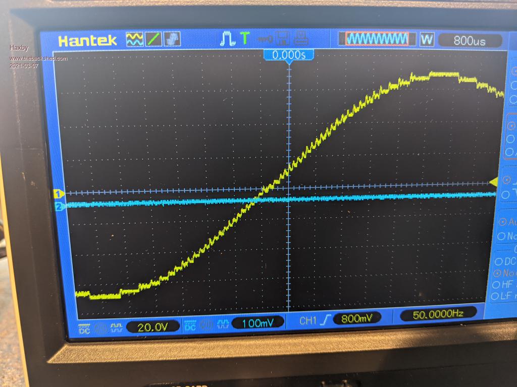 |
||||
| Warpspeed Guru Joined: 09/08/2007 Location: AustraliaPosts: 4406 |
To me, that looks like capacitive coupling between the primaries and secondaries, plus a bit of ringing. More filtering perhaps? Try putting a very few uF directly across the 230v output. Cheers, ĀTony. |
||||
| Haxby Guru Joined: 07/07/2008 Location: AustraliaPosts: 418 |
This is 2uf. Looks good to me! 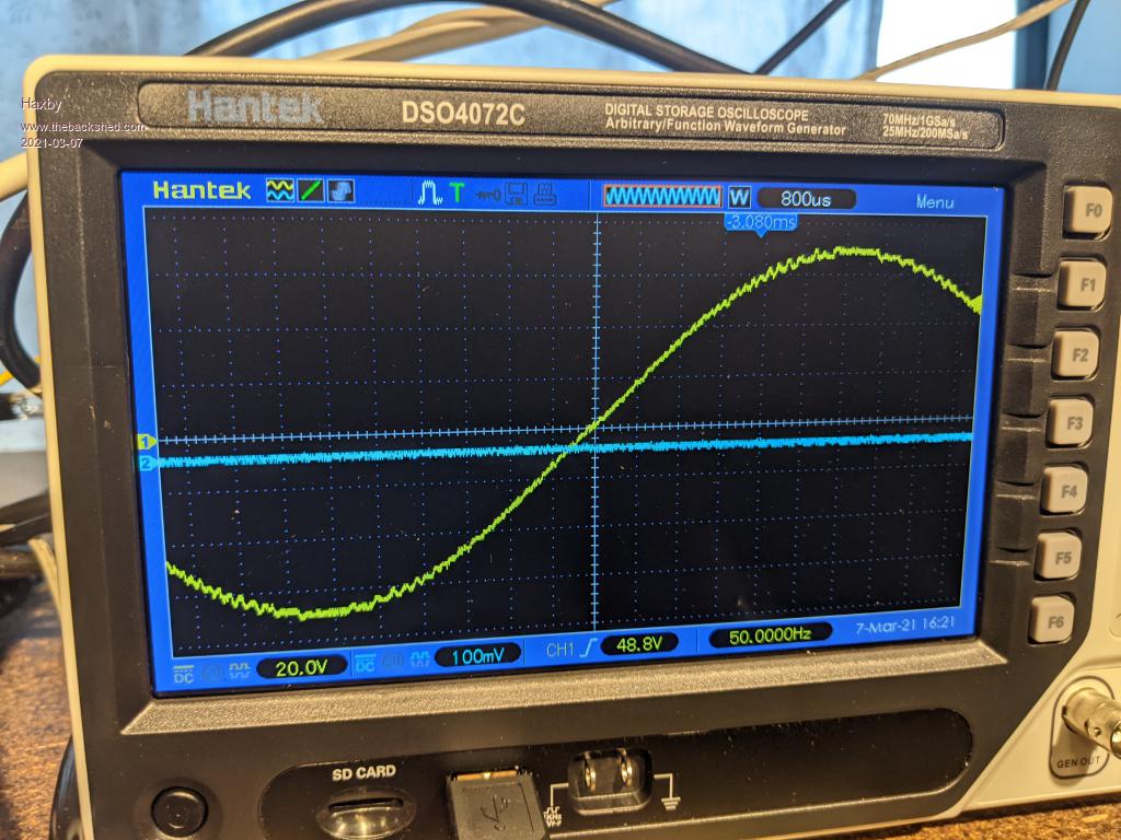 |
||||
| Warpspeed Guru Joined: 09/08/2007 Location: AustraliaPosts: 4406 |
That will be fine. Cheers, ĀTony. |
||||
| Haxby Guru Joined: 07/07/2008 Location: AustraliaPosts: 418 |
Earthing: The Prius constantly senses any earth leakage on both the positive and negative HV battery cable and shuts off the HV battery on both pos and neg if it detects leakage. So the battery side of my inverter is isolated from ground. For the AC mains side, should I connect neutral and earth together at the inverter socket? I'm thinking it would be safer to keep both active and neutral floating with respect to ground. Like an isolation transformer. The chassis of the inverter would be connected to the car body, and I'd have an RCD on the mains output. Thoughts? |
||||
| Warpspeed Guru Joined: 09/08/2007 Location: AustraliaPosts: 4406 |
A fully floating system is safer in theory, and in fact it is done in places like operating theaters and intensive care wards, where electrocuting a patient with only a couple of milliamps is a real possibility. One very special isolation transformer per patient is the norm. But in a large distributed power system, there will be leakage to ground and capacitance to ground everywhere, and you will not see the desired benefits of a true fully floating system. Much safer to ground the neutral side right at the power source (inverter or main power board) to an earth stake or a cold water pipe, and use residual earth leakage detecting circuit breakers for each separate circuit in the distribution system. Its the safest way, and I believe now a statutory requirement anyway. Cheers, ĀTony. |
||||
| Haxby Guru Joined: 07/07/2008 Location: AustraliaPosts: 418 |
This will be a portable generator for an air compressor and a slide saw. It won't be connected to a house. I wonder if commercial portable generators and say 12v inverters connect the neutral and earth internally? My gut feeling is that they don't? |
||||
| Warpspeed Guru Joined: 09/08/2007 Location: AustraliaPosts: 4406 |
A portable generator has no real way of connecting to a proper ground anyway. As you say its almost certainly floating. Cheers, ĀTony. |
||||
| Haxby Guru Joined: 07/07/2008 Location: AustraliaPosts: 418 |
What total system continuous power rating should my warpverter transformers have if I'm using a 3kw transformer for the biggest inverter? I know that some inverters are 'negative' whilst other inverters are 'positive' so it's not a matter of adding all the transformer ratings together eg. 3+1+0.3+0.1= 4.4kw Having a look at Poidas graph back early in this forum, I'd say I've got something around a 3.3kw system power. Is that about right? |
||||
| Warpspeed Guru Joined: 09/08/2007 Location: AustraliaPosts: 4406 |
Continuous power rating only depends on the temperature rise, of both the junction temperatures and transformer temperature rise. And that is a judgement call rather than a hard limit. With the transformers running at four amps per mm square design current density, it will run "pretty warm" but take perhaps an hour for the transformer temperatures to plateau. Temperature rise is proportional to current squared, so beyond four amps per mm square, it starts to get a lot hotter fairly quickly. That can be mitigated with fan cooled assistance, but there are definite limits to that approach, as the conduction losses increase square law with power output. Now transformer ratings for a Warpverter are interesting, because a lot of power circulates between the transformers when one of the series secondary windings is in opposition to the others. Power flows backwards back into the dc power rail. So the transformers will all be working a fair bit harder than the total final power output. For example: Largest transformer 225v @ 15 amps = 3,375 Va Number three 75v @ 15 amps = 1,125 Va Number two 25v @ 15 amps = 375 Va Number one 8.3v @ 15 amps = 124.5 Va Total transformer power 4,999.5 Va. However, the output from the inverter as a whole (in this example) would be 235v at 15 amps = 3,525 Va. So you rate your inverter as final inverter rms output voltage x the design secondary rms current. In this example, would be 3.5 Kw continuous, with a surge capability of multiples of that, provided your dc source does not buckle at the knees. All this circulating power might seem inefficient, and in a way it is. But the final overall flat out efficiency will be in the region of 92% to 94% about the same as a good pwm Oz inverter of similar power rating and load. Cheers, ĀTony. |
||||
| Haxby Guru Joined: 07/07/2008 Location: AustraliaPosts: 418 |
I understand what you mean Tony, thankyou! So the total transformer power is around 5% more than the rating of the biggest transformer in the system. That puts my system at around 3.15kva give or take. My warpverter is able to regulate the output with anywhere from 200 to 400vdc input, but does the continuous power rating of the transformers change based on the battery voltage? Or does the change in duty cycle of the square wave keep the continuous power constant? Asked another way, if I continuously run at 200vdc input, will the transformers stay at the same temperature as when I continuously run at 400vdc input? (Given the same load of course) |
||||
| Warpspeed Guru Joined: 09/08/2007 Location: AustraliaPosts: 4406 |
Yes, everything stays pretty constant. Transformer heating only comes from current, and if the load is 3.15 Kva, and stays at 3.15Kva, and the final output voltage remains a 235v sine wave at the output, nothing really changes as far as heating or transformer saturation goes, as the dc input voltage changes. The rectangular voltage waveforms across each transformer will vary considerably in peak voltage and duty cycle, as you would expect. But the volt/microseconds and the overall effect is a constant final sine wave voltage output, and a constant sine wave current through all of the transformer windings, primaries as well as secondaries. Its a weird thing to try and visualise !! If everything is initially designed to work at the minimum incoming dc voltage, it will work fine up to twice the minimum dc voltage. Cheers, ĀTony. |
||||
| Haxby Guru Joined: 07/07/2008 Location: AustraliaPosts: 418 |
Thanks for that Tony. On an unrelated topic, I'm designing a 3 phase mega breakout board for Poida's Mega code. It will have 3 X 16 way ribbon cables as logic outputs, each ribbon cable will connect to one of 3 of my igbt boards. The question is whether I can put the dead time capacitors on the mega board or whether they are better placed as close as possible to the igbt driver ICs? I'm guessing that they are better as close as possible to the IGBT driver ICs for noise immunity? If it doesn't make a difference, I'd prefer them on my mega breakout board. |
||||
| Warpspeed Guru Joined: 09/08/2007 Location: AustraliaPosts: 4406 |
It does not really matter where they go, either end of the cable will work well. I have not forgotten about laying out a circuit board for the EPROM based "Warpverter simulator". I have my original Verro board prototype, plus hand drawn schematic, plus the EPROM data in front of me at the moment. Not sure if I have any suitable blank EPROMS though? Must pull my finger out and get started on it. I have been busy out back playing around with my engines. I have a thread going on another Forum about that, which now has about eighty people subscribed. There is a lot of interest in it, and I must keep working on it to be able to keep posting some kind of progress... Cheers, ĀTony. |
||||
| Haxby Guru Joined: 07/07/2008 Location: AustraliaPosts: 418 |
Since I'm not an eeprom wrangler nor Arduino coder, I don't have a burning reason to have a warpverter simulator, so no hurry at this end. Can you point us to the engine thread? |
||||
| Warpspeed Guru Joined: 09/08/2007 Location: AustraliaPosts: 4406 |
There is a bit of a background to all this engine nonsense. Mazda MX5 sports cars have a pretty loyal following worldwide, many are raced at weekends. Fun racing by enthusiasts on a very tight budget. The problem is the engines have a relatively long stroke and very short connecting rods. Big side thrust loading on the pistons, and terrible problems with piston rock and ring sealing. Guys hot these up with turbochargers and then they regularly shred gearboxes. The common fix to the gearbox problem is to fit a BMW gearbox, which is relatively cheap readily available and VERY strong. The kits to do this are horribly expensive and fabricating a home brew BMW gearbox/MX5 conversion beyond the resources and ability of most people. So its the expensive kit or nothing. Anyhow, quite by chance I discovered that the excellent Mazda MX5 cylinder head bolts straight onto the top of a BMW 318i engine block. Not only that, the BMW gearbox bolts straight onto the BMW engine (obviously). What has everyone really excited is its a cheap and relatively straightforward job. A lot of work, but no multi thousand dollar kits of parts required. All you need are basic hand tools that everyone already has and a bit of enthusiasm. You get a much better engine, a much stronger gearbox, and the cylinder head still says Mazda on top, and it will all look fairly original when back in the car. https://forum.miata.net/vb/showthread.php?t=727566&highlight=rod+ratio&page=2 Cheers, ĀTony. |
||||
| Haxby Guru Joined: 07/07/2008 Location: AustraliaPosts: 418 |
Stacking toroidal transformers on top of each other: I'm working on the 3 phase inverter and thinking about whether there is any issue in stacking them vertically in very close proximity to each other. See pic where phase 3 (bottom row) is stacked. Other than heat dissipation, will there be any magnetic fields influencing neighbouring transformers? 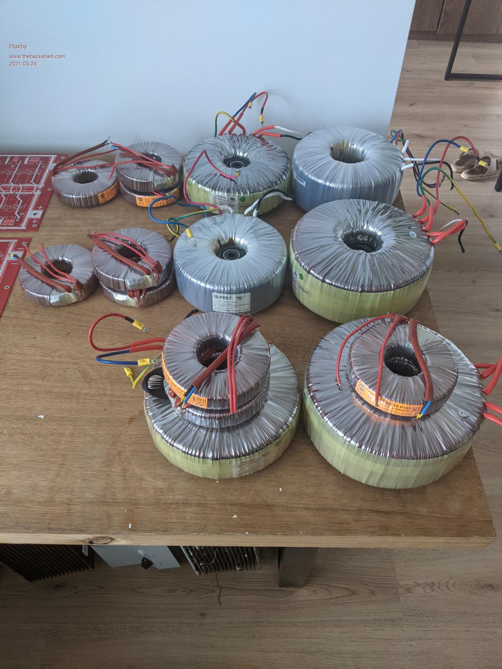 |
||||
