
|
|
Forum Index : Microcontroller and PC projects : Help for Idea ....
| Author | Message | ||||
| hitsware2 Guru Joined: 03/08/2019 Location: United StatesPosts: 738 |
I would like to build ( or perhaps simply program ) a matrix oscilloscope . Something like : 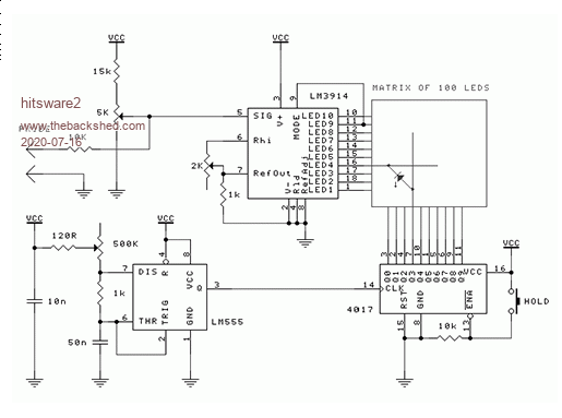 But more like 64 x 128 ( 255 x 255 ? ) Since higher resolution displays have no pin out to rows and columns What ( I think ) I need is a display + display controller + micro ( processor and / or controller ) that will produce a ' pset ' at the conjunction of 2 8-bit values . NOT storage of the whole screen , but simulation of a CRT .... I.E. oscillator driving 8 bit counter on columns and 8 bit flash A to D on rows ......... my site |
||||
| vegipete Guru Joined: 29/01/2013 Location: CanadaPosts: 1179 |
I found good prices for LED modules at this supplier but interfacing to these displays is a little bit involved. A simple arduino can handle smaller modules, more grunt is needed for bigger ones. Because the modules need fast continuous refresh, a Micromite likely can't handle it without internal firmware support. Once the module and controller are figured out, they can be treated like any other display as far as a Micromite is concerned. Then again, because the modules are shift register driven, it might be possible to do everything with discrete TTL. The tough part is the 'strange' interleaving of the module columns... Visit Vegipete's *Mite Library for cool programs. |
||||
| matherp Guru Joined: 11/12/2012 Location: United KingdomPosts: 11499 |
This any use as a display? |
||||
| hitsware2 Guru Joined: 03/08/2019 Location: United StatesPosts: 738 |
If it was .... Could I simulate an analog (crt) with it ? One pixel on at a time .. Chosen by by 2 values .. No storage .. my site |
||||
| matherp Guru Joined: 11/12/2012 Location: United KingdomPosts: 11499 |
It just acts as a standard display using all the normal graphics commands so PIXEL x,y,colour lights a specific LED |
||||
| hitsware2 Guru Joined: 03/08/2019 Location: United StatesPosts: 738 |
> Current refresh rate is 62.5FPS on an MX170 Micromite How would that effect trying to emulate a CRT ? Doesn't it imply some kind of storage ? Or do S.S. displays all demand that ? ( I may be getting beyond my technical capacities :( ) my site |
||||
| darthvader Regular Member Joined: 31/01/2020 Location: FrancePosts: 100 |
Algorithm for this will be: for time base of 10mS Time_Base = 10 Ms_Time = Actual_Time For X = 0 to MM.Hres While (Ms_Time + Time_Base ) < Actual_Time : EndWhile Show LED at X , ADC Value Ms_Time = Actual_Time Next X Loop this function if needed ... Translate this to MMBasic code  Storage in scope function is useless , what you need is the max performance. Now if you need storage , you have to record each ADC Values in a defined array that you can show it after the measure. But from what i read here it's not the case .... Cheers. Theory is when we know everything but nothing work ... Practice is when everything work but no one know why ;) |
||||
| hitsware2 Guru Joined: 03/08/2019 Location: United StatesPosts: 738 |
What would be the bandwidth of the ADCs on the CMM2 ? my site |
||||
TassyJim Guru Joined: 07/08/2011 Location: AustraliaPosts: 6538 |
Latest beta has improved things: I have used a sample frequency of 400kHz = 2.5uS sample rate. Its really good feature is this happens in the background so you can do other things while sampling. Jim VK7JH MMedit |
||||
| hitsware2 Guru Joined: 03/08/2019 Location: United StatesPosts: 738 |
How would that translate to bandwidth ? Could I put 1 kHz into a pin and get a display of it onto the VGA out ? Something like : do for x = 0 to 255 pixel x , readadc pin pause ? cls next x loop Edited 2020-07-17 11:40 by hitsware2 my site |
||||
| The Back Shed's forum code is written, and hosted, in Australia. | © JAQ Software 2026 |
