
|
|
Forum Index : Microcontroller and PC projects : CMM2 Oscilloscope fun
| Author | Message | ||||
| KeepIS Guru Joined: 13/10/2014 Location: AustraliaPosts: 2177 |
I�ve been wanting to have a play with the ADC on the CMM2 and was prompted by TassyJim and his really nice temperature sensor capture program. I wanted to be able to quickly change the Sample Frequency and Trigger levels on the fly and quickly came up with this little Oscilloscope program. 1: Sample frequency in 100Hz steps from 100Hz to 5KHz 2: Trigger level from -3.3 to + 3.3 and single key to switch Trigger polarity 3: Trigger line on display and time period follows sample Frequency. To show Sine waves the ADC input needs a DC offset at half the value of the P-P value of the waveform. Digital signals that aren�t negative going don�t need this. A quick and dirty way to show external sine wave (AC) signals is to use a variable resistor of around 100k connected between 3v and ground, the centre slider is taken to the ADC input and the sine wave signal is coupled with a 1uf cap to the centre slider. Turning the variable resistor moves the trace up and down the screen, at 1.5 volts a sine wave with a peak to peak voltage of up to 3 volts will show without clipping. Be sure to keep any input voltage to the CMM2 ADC below 3.3v Ideally you would an OP-AMP with adjustable DC offset for audio (analogue) work or digital signals that also go negative. Incorporated in a simple circuit would be adjustable gain with selectable input voltage ranges. Such as it is, the program might be a bit of fun for someone to play with. 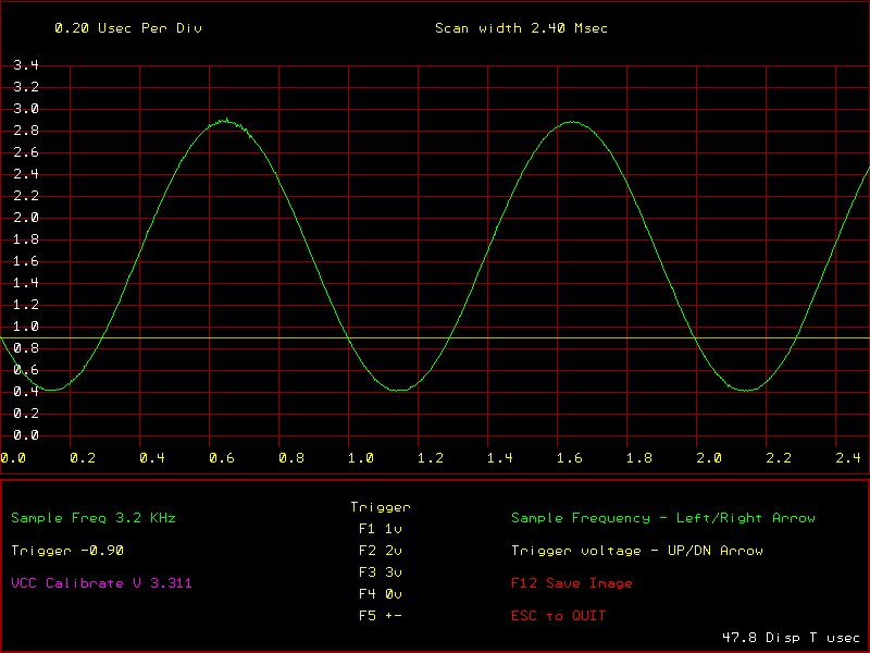 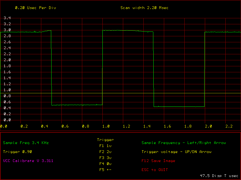 AudCRO.zip . NANO:Inverter V 8.2ks - Linux AvrDude GUI script V4.1 |
||||
| hitsware2 Guru Joined: 03/08/2019 Location: United StatesPosts: 738 |
Right On !  I hope to do a very crude oscilloscope . No trigger .... Variable sweep speed . No text ( perhaps graticule ) How much time does it take to sample the input ? I want to emulate a CRT .... No storage .... Just as ' real time ' as possible ... my site |
||||
| KeepIS Guru Joined: 13/10/2014 Location: AustraliaPosts: 2177 |
Hi, the average time is 49usec, the display at the bottom RH side of the screen is the total Sample + Display time in usec. NANO:Inverter V 8.2ks - Linux AvrDude GUI script V4.1 |
||||
TassyJim Guru Joined: 07/08/2011 Location: AustraliaPosts: 6538 |
That's up to you. Assuming you want to fill a 800x600 screen, take 800 samples at a time. The ADC will take the 800 samples in the background then swap to the second array. While the ADC is sampling one array, your program displays the other array of data. If you sample at 100kHz, the 800 samples takes 800*1/100000 = 8mS That's how far behind your display will be. Every 8mS, you swap arrays so that the 'other one' gets displayed. If you want to display mains frequency, sampling at 10kHz will give 80 mS or 4 and a bit of your cycles. You would probably want to use the trigger so the waveform is steady. Jim VK7JH MMedit |
||||
| KeepIS Guru Joined: 13/10/2014 Location: AustraliaPosts: 2177 |
FYI, I added Peters FFT for a frequency readout, because I'm trying to cover 100Hz to 500Khz sample frequency it's slightly off on some samples rates but still in the ballpark and often spot on, it also depends on nature of the input signal. Mike. EDIT: Added Trigger on/off . Edited 2020-07-25 16:54 by KeepIS NANO:Inverter V 8.2ks - Linux AvrDude GUI script V4.1 |
||||
| hitsware2 Guru Joined: 03/08/2019 Location: United StatesPosts: 738 |
Then this idea is bunk ? ( I would like to ( using the VGA monitor ( and a single ADC pin ) ) ) have it act like an 8bit x 8bit matrix . I . E ...... Only 1 pixel ( or mini sprite ? ) would display at one time . Edited 2020-07-26 00:23 by hitsware2 my site |
||||
| TassyJim Guru Joined: 07/08/2011 Location: AustraliaPosts: 6538 |
You don't have to use the background ADSC. You can simply read the analog pin and process how ever you wish. I don't know what refresh rate you will be able to achieve but should be easy enough to try. Jim VK7JH MMedit |
||||
| hitsware2 Guru Joined: 03/08/2019 Location: United StatesPosts: 738 |
Loaded and ready for bear  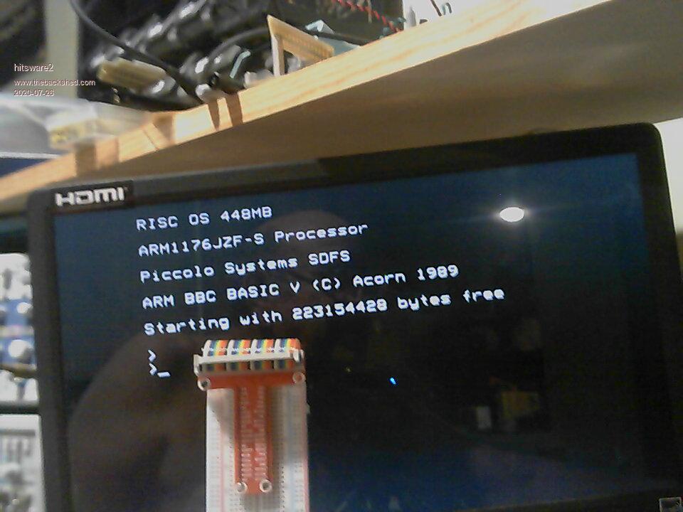 my site |
||||
| Volhout Guru Joined: 05/03/2018 Location: NetherlandsPosts: 5931 |
The pi doesnt have analog inputs. Bbc basic is fast, but not exremely fast. You can sample a pin in basic at roughli 1msps. For faster, up to 20 msps use the build in assembler. Ah..i think this post is in the wrong section. Edited 2020-07-27 02:57 by Volhout PicomiteVGA PETSCII ROBOTS |
||||
| hitsware2 Guru Joined: 03/08/2019 Location: United StatesPosts: 738 |
I know . I am ( at this point ) simply trying to get a trace . I hadn ' t considered syncronizing with the display . I get what appears as row of flickering random dots : ( RISC BBCBasic has a WAIT that supposedly addresses the video problem but slows it to unusability . Edited 2020-07-28 00:54 by hitsware2 my site |
||||
| hitsware2 Guru Joined: 03/08/2019 Location: United StatesPosts: 738 |
Practicing for coming CMM2 CLG y=125 do color white rect 100,50,151,151 color black text 30,110,"VOLTAGE" text 45,95," ^" text 45,125," v" text 151,205,"< TIME >" for x=100 to 250 r=rand*100 if r>50 then y=y+1 if r<50 then y=y-1 if y>200 then y=200 if y<50 then y=50 plot x,y next x until false my site |
||||
| hitsware2 Guru Joined: 03/08/2019 Location: United StatesPosts: 738 |
setpin 7, ain, 8 do while inkey$ = "" cls for x% = 300 to 555 pixel x%, 300*pin 7 next x% loop end ' ~ 45 Hz ( I'm sure ' there is a truth there ) 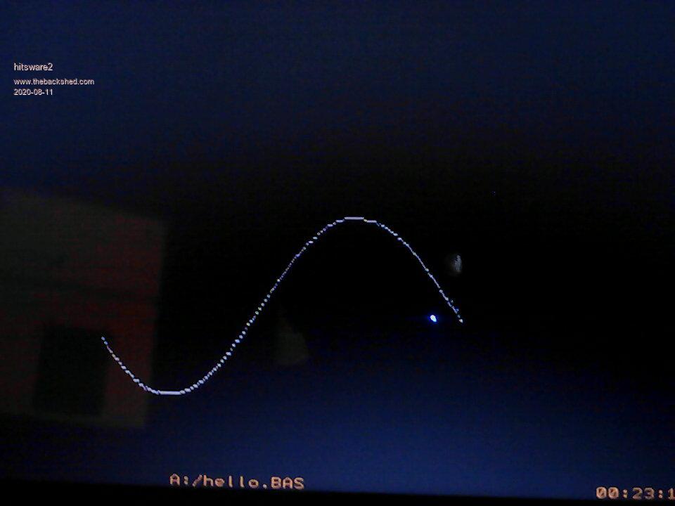 my site |
||||
| The Back Shed's forum code is written, and hosted, in Australia. | © JAQ Software 2026 |
