
|
|
Forum Index : Microcontroller and PC projects : MX170 oscilloscope idea
| Author | Message | ||||
| robert.rozee Guru Joined: 31/12/2012 Location: New ZealandPosts: 2528 |
a while back peter produced a simple oscilloscope (using a C-function) that ran on any micromite from an MX170 upwards: http://www.thebackshed.com/forum/ViewTopic.php?TID=8077 as far as i can tell, peter's design could sample a single analog input at close to 2Msps, and there was also a version that could do 8 channels of digital at around 7Msps. these are pretty impressive numbers. prompted by recent discussions on the forum, i've been thinking about revisiting the idea - of a really simple oscilloscope-like program for the micromite to help forum members diagnose problems in their projects. but whereas peter's design had triggering and the display functionality built into the C-function, i'm thinking more along the lines of: 1. a high-speed data acquisition system that, 2. continuously grabs a whole load of samples into a circular buffer until, 3. a 'trigger' input is received, after which, 4. an 'exit' countdown timer is set. 5. sampling continues until the countdown timer reaches zero, 6. upon which the C-function exits. an mmbasic program can then decode and display the collected samples (up to 50,000) itself. if possible, the PIC32's ADC would be configured as 8-bit only. indeed, 6-bit would be acceptable in most cases. the C-function would be passed (A) a pointer to a buffer, (B) the buffer size, (C) the sample rate, (D) the pins(s) to sample from, (E) a 'trigger' pin, (F) the start value to use for the countdown timer. samples would be packed into the array, with options of: single channel analog input, 2-channel analog input (interleaved), or single analog and 8 digital input (data interleaved). triggering would be handled outside of the MX170 with selection between: external circuitry (zero-crossing, rising/falling edge, pulse window, etc), a 555 timer running at the desired 'frame rate', or just a user push-button. as this scope would be primarily intended for looking at what a micromite (or other micro) is doing, no front-end would be necessary beyond perhaps an op-amp buffer. is this worth developing further? cheers, rob :-) |
||||
| JohnS Guru Joined: 18/11/2011 Location: United KingdomPosts: 4335 |
It _sounds_ good but I don't know enough to help, sorry. John |
||||
| hitsware2 Guru Joined: 03/08/2019 Location: United StatesPosts: 738 |
How about ? : ( No trigger ( just for proof of concept ) ) 1) one sample at a time 2) sweep is x co-ordinate for PIXEL ( FOR x = ? TO ? ) 3) value at ADC pin is y co-ordinate ( y = VAL ( ADC ) ) * or / ? 4) CLS after each display Like a CRT my site |
||||
| Volhout Guru Joined: 05/03/2018 Location: NetherlandsPosts: 5931 |
You would be able to make a ver simple scope from that. I would love to join in on that project, but have never tried to create a cfunction. Sinve this may be quite hardware dedicated, you have to pick a platform ( MX170 you proposed). Personally I think you would love to base it on a platform with more memory. I must admit though that it will be a very basic scope. Even if you could sample up to 1 mbps for 2 channels. If there are limitted trigger options (basically edge trigger only) you need deep memory and search options to find what you are looking for. If you want this for new micromite enthousiasts, remember that they need this, and their original micromite/cmm2 to work on the problem. The digital inputs. I personally use a saleae clone, 24msps, bus decoding, 8 bits, sheer infinite memory, for 10 us dollar. Not a lot that can beat that. I would focus on the scope part mainly. Volhout. PicomiteVGA PETSCII ROBOTS |
||||
| robert.rozee Guru Joined: 31/12/2012 Location: New ZealandPosts: 2528 |
essentially, what i'm describing is the underlying mechanics of a DSO (digital storage oscilloscope), whereas what you are describing is the underlying mechanics of a CRO (cathode ray oscilloscope). since they first appeared, manufacturers attempted to make their DSO's look and behave like a CRO - in the early days this was relative unsuccessful. the idea was to encourage engineers to buy the machines by making them look and act like something familiar. a CRO is primarily orientated towards displaying a repetitive signal, with the trigger mechanism there to line up overlaying images on top of each other in a coherent fashion. this worked, more-or-less, for a repetitive signal with a frequency above the persistence of the CRT phosphor. a DSO captures a series of samples, where there may be only ONE trigger event. afterwards, the DSO presents these samples as a graph. if the DSO is fast enough and has enough clevers, it can do this quickly and seamlessly enough to creating a series of images reminiscent of what a CRO may produce. alas, a CRO is of limited usefulness when dealing with data coming out of a microcontroller. cheers, rob :-) |
||||
| robert.rozee Guru Joined: 31/12/2012 Location: New ZealandPosts: 2528 |
the 'competition' is something like a Hantek DSO5072P, which can be had for under us$200 on occasion. that price-point excludes PCB, display, user controls, etc. i'm thinking of minimal hardware, minimal cost, with an application running on a PC to manipulate and display the output. the MX170 would be there to (1) be configured from the PC with things like sample rate, buffer size, etc, (2) be told to capture data to the onboard 50kpts buffer, and (3) return the contents of the buffer upon request. the hardware of the oscilloscope would be the MX170, usb to serial bridge, and perhaps a single op-amp configured as a voltage-followed for analog input buffering. all plugged together on either a bit of veroboard or a solderless breadboard. cheers, rob � :-) Edited 2020-07-27 02:39 by robert.rozee |
||||
| hitsware2 Guru Joined: 03/08/2019 Location: United StatesPosts: 738 |
> alas, a CRO is of limited usefulness when dealing > with data coming out of a microcontroller. As is a DSO for watching music signals . my site |
||||
| hitsware2 Guru Joined: 03/08/2019 Location: United StatesPosts: 738 |
> the 'competition' is something like a Hantek DSO5072P, Speaking of which : 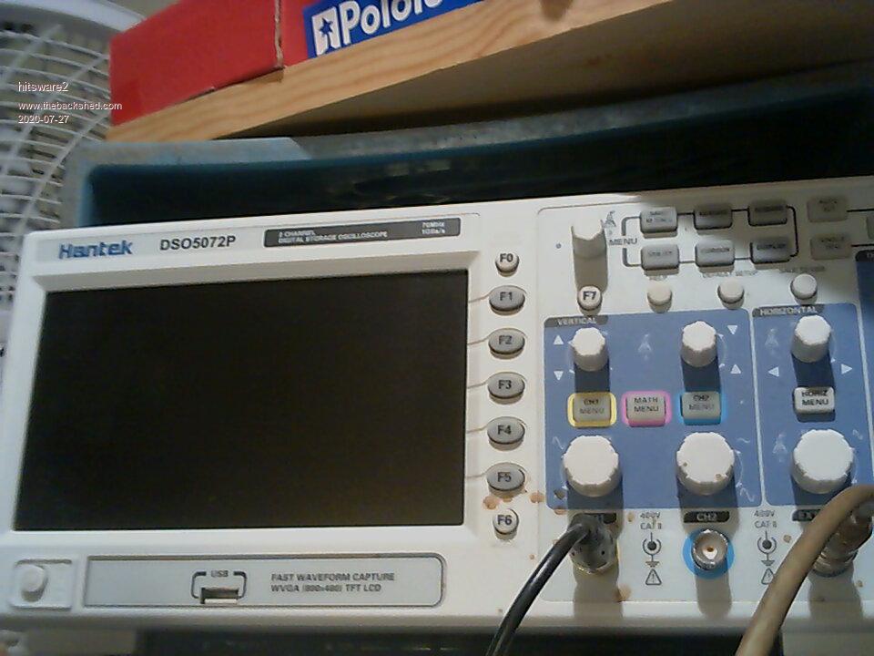 my site |
||||
| hitsware2 Guru Joined: 03/08/2019 Location: United StatesPosts: 738 |
Using RISC BBCBasic on RPi ... 10 MODE 27 20 FOR x = 0 TO 1000 30 POINT x , 300 40 CLS 50 NEXT x 60 GOTO 20 Gives a ( sorta like ) trace but needs to someways be syncronized with the display . Looks more like a line of random dots my site |
||||
| JoOngle Regular Member Joined: 25/07/2020 Location: SwedenPosts: 82 |
Hi, I find this project to be very interesting. In fact , making a scope interface for the CMM2 was on my "scope" so to speak when I first heard of it, as it could be quite useful for that, here's my input and some ideas: 1) First of all, it's very important to separate the electronics from the scope external parts, because our CMMS's are very sensitive to statics, electric overload, high voltages etc, as mentioned with the 3.3v interface. This could be easily achieved with Photocouplers/optocoupler. This separates the electronics from each other, also limits the interfacing part to max 3.3v signals from the scope electronics. This protects the CMM2 from any circuit overload or/and high voltages, and faulty experiments from our side. This is essential. 2) Although the CMM2 is very fast indeed, I remain skeptical to how FAST the scope would be if everything was left to BASIC coding in CMM2, this could however be achieved with some ARM RISC code (if possible to load into CMM basic somehow?) as a module, it sort of defeats the whole Basic Only concept of CMM series, but it's not unheard of as for example when I worked with Commodore 64 back in the days, I did learn Assembly programming in order to support the basic code with things that was simply too slow for a real-time basic interpreter. I think including assembly routines in code is perfectly acceptable. For this I wish there was an ASM programmer included in CMM in the future as well (maybe there is already, I just don't know yet), then the CMM2 is at least absolutely fast enough to not need complex sampling hardware externally. If this goes against the whole policy of CMM concept, then I think an external sampling unit (compared to the sampling scopes you get for any other computer) must be done in order to achieve actually USABLE (beyond sound) scope frequencies, minimum of 20 MHz bandwidth in my electronics experience. I have 20-200 MHz Oscilloscopes myself in my lab, and I prefer stand-alone units in comparison to PC scopes, because I like the simplicity of just "turning an unit on, and it's ready to fault-find and repair with". 3) I got additional ideas / plans for an electronics interface for the CMM2, I was thinking features like: 1) Voltmeter. 2) Frequency generator / Function tester. 3) Logic Analyzer (this one is a no-brainer, could be done very easily as-is with a CMM2 (even CMM and the older series) with little coding, and a simple optocoupler device with 8-16 bit (maybe even more) data acquisition channels for monitoring external communication / chips /eproms /processor buses etc. 4) Spectrum analyzer, now this part is particularly advanced, and I don't think the CMM series could do without serious external parts, it would require at least an SDR (Software Defined Radio), could be done in Assembly partially if allowed and possible, this would save on parts, but if not - it would need an external microprocessor to handle the SDR part and scanning together with the IF/RF parts. I already have a bunch of real expensive but somewhat older Spectrum Analyzers, they are the most FUN instruments you'll ever own IMHO. The voltmeter is also interesting, because it can be used to monitor voltage changes (spikes etc.) over a longer period of time, very little external parts are required to do this part, and it will be of tremendous use for anyone needing to do some statistics on power usage, voltage discrepancies and deviations - which is a must when you develop hardware or fault find on intermittent issues, something that is beyond most voltmeters, even today, unless you wanna spend in the 2K$ range which most of us probably won't, but would like to have nonetheless. Just my 2 cents. |
||||
| hitsware2 Guru Joined: 03/08/2019 Location: United StatesPosts: 738 |
Isn't the below ( per Matherp ) in fact ' assembly ' or even ' machine language ' CFunction scope 00000000 3C029D00 8C480094 27BDFF70 AFB40078 8D140000 8C430000 8C480098 001458C0 00141140 8C6A0000 01621021 AFB1006C 8D110000 3C081062 25084DD3 00026080 01480019 3C03BF81 004C1021 8C8C0000 8FA400B0 8C69F220 AFB20070 00004010 3C0A0661 8C920000 8FA400B4 7D29D800 354BA053 AFB30074 AFBF008C AFBE0088 AFB70084 AFB60080 AFB5007C AFB00068 8FAD00AC 2631FFFF 00084182 112B02B2 8C930000 8C64F220 254AA053 7C84D800 008A5026 2403001C 2404002C 008A180A 3C04BF81 8C8BF220 8C89F220 3C040580 3484A053 7D6BD800 01645826 240A0040 7D29D800 24841000 112402AC 014B180A 28630033 24090028 0143480A 8CAA0000 8CA40004 01441825 1060026E 00141840 00E3A821 AFA60024 00C31821 AFA70028 000A5027 00042027 ACAA0000 ACA40004 71884002 10000002 24100001 00808021 0050001B 020001F4 00002812 0105001B 00A001F4 0000B812 02E9282B 14A0FFF7 26040001 8FA200A8 8C470000 14E00264 2405FFFF 8DA80000 0008280B 00073823 7C073E20 19000265 AFA0001C 3C021000 3C0FBF88 ADE21064 2404FFFF 34028000 3C06BF81 3C18BF88 AF001068 AFA40020 ACC29004 3C04BF81 8C89F220 3C020661 7D29D800 3446A053 11260265 7C084620 8C86F220 2444A053 7CC6D800 00C43026 2402001C 2404002C 0086100A 3C04BF81 8C8AF220 8C86F220 3C040580 3484A053 7D4AD800 01445026 24090040 7CC6D800 24841000 10C40226 012A100A 28420033 10400223 3C040C00 3C02BF81 AC449040 3C02BF88 AC406118 3C02BF88 AC406108 3C04FFFF 3C02BF81 AC449050 24040200 3C02BF81 AC449020 24040007 3C02BF81 AC449010 340480E4 3C02BF81 AC449000 3C02BF81 34048000 AC449008 3C020008 ADE21064 3C16BF81 AF001068 8EC29010 7C4201C0 1040FFFD 00000000 3C0ABF81 3C09BF81 8D429070 8D229080 8EC29010 30420080 1440FFFD 3C0DBF81 0290001B 020001F4 3C0BBF81 8DA490F0 8D649100 8D469070 8D249080 24C60001 24840001 A4660000 A6A40000 0000A012 40824800 12800230 00003021 0000F021 00007021 3C0C9D00 8EC29010 7C4201C0 1040FFFD 00000000 40024800 0057001B 02E001F4 00002012 03C4102B 1040000A 00000000 8D449070 8D229080 10A0019A 001EC840 0079F821 02B9C821 A7E40000 27DE0001 A7220000 8EC29010 30420080 1440FFFD 00000000 40024800 0057001B 02E001F4 00002012 03C4102B 1040000B 03D4102B 8DA490F0 8D629100 10A0013E 001EC840 0079F821 02B9C821 A7E40000 27DE0001 A7220000 03D4102B 1440FFD6 3C04004C 24844B40 00C4302B 3C041000 ADE41064 3C020008 34048000 3C05BF81 AF001068 ACA49004 ADE21064 AF021068 10C001F1 3C029D00 8C420098 8C560000 3C028888 34428889 02C20019 8FA200A0 0000B010 8C470000 0016B1C2 0016B180 04E00063 0016B843 2E820002 14400060 8FA80024 240B0001 AFB50024 AFB0001C AFB3002C 0000F021 3C0A9D00 24023057 01608021 01009821 0060A821 10000003 AFB40020 8FA400A0 8C870000 86650002 86680000 70A22802 71024002 00B2001B 024001F4 8FA6001C 24030001 240400FF AFA40014 AFA30010 8D430050 03C0A021 03C6F021 02802021 03C03021 AFA20030 AFAA0060 26100001 26730002 00002812 0112001B 024001F4 00B72821 00004012 01174021 0116001B 02C001F4 00004812 00B6001B 02C001F4 02292823 00A72823 00004012 02284023 0060F809 01073823 86A50002 8FA20030 86A80000 70A22802 71024002 00B2001B 024001F4 8FA300A0 3C0600FF 8FAA0060 24040001 34C6FFFF 8C670000 AFA40010 AFA60014 8D430050 02802021 03C03021 26B50002 00002812 0112001B 024001F4 00B72821 00004012 01174021 0116001B 02C001F4 00004012 00B6001B 02C001F4 02282823 00A72823 00004812 02294823 0060F809 01273823 8FA30020 8FA20030 1603FFB2 8FAA0060 8FB50024 8FB0001C 8FB3002C 8FB40020 8FA500A4 8CA70000 04E0005B 2E820002 14400059 8FA20028 24030001 AFB00018 AFB4001C 00009021 3C099D00 241E3057 00608021 10000003 0040A021 8FA300A4 8C670000 86850002 86880000 70BE2802 711E4002 00B3001B 026001F4 8FA40018 24020001 240300FF AFA20010 AFA30014 02401021 8D230050 02449021 02403021 00402021 AFA20030 AFA9005C 26100001 26940002 00002812 0113001B 026001F4 00B72821 00004012 01174021 0116001B 02C001F4 00005012 00B6001B 02C001F4 022A2823 00A72823 00004012 02284023 0060F809 01073823 86A80002 86A50000 711E4002 70BE2802 0113001B 026001F4 8FA300A4 8FA20030 24040001 8C670000 AFA40010 00402021 3C0600FF 8FA9005C 34C6FFFF AFA60014 8D230050 02403021 26B50002 00004012 00B3001B 026001F4 01171021 00002812 00B72821 00B6001B 02C001F4 00002812 0056001B 02C001F4 02252823 00A72823 00001012 02221023 0060F809 00473823 8FA2001C 1602FFB3 8FA9005C 8FB00018 02009021 00009821 3C029D00 8C420098 8C420000 10400016 3C150080 00008021 3C149D00 24160001 36B58080 8E820094 02002821 8C460000 AFB60010 AFB50014 8E820050 02003821 00002021 0040F809 24C6FFFF 8E820098 8C420000 000218C2 02038021 0202102B 5440FFF1 8E820094 3C029D00 8C420094 8C460000 10C00018 3C160080 3C15CCCC 00008021 3C149D00 24170001 36D68080 36B5CCCD AFB70010 AFB60014 8E820050 02003021 02002021 00002821 0040F809 02203821 8E820094 8C460000 00D50019 00001010 000210C2 02028021 0206102B 5440FFF1 AFB70010 3C140080 36948080 24150001 3C109D00 AFB50010 AFB40014 8E020050 02202821 02203821 00002021 0040F809 24C6FFFF 8E020094 02203821 8C440000 AFB50010 AFB40014 8E020050 2484FFFF 00002821 0040F809 00803021 8FBF008C 02401021 02601821 8FBE0088 8FB70084 8FB60080 8FB5007C 8FB40078 8FB30074 8FB20070 8FB1006C 8FB00068 03E00008 27BD0090 10E00006 8FB9001C 1320006E 84790000 0327C82A 57200091 0087282B 5100000A A4640000 8FB90020 1320006D 86B90000 0328C82A 13200004 A4640000 0048F82B 0005C827 033F280A A6A20000 01C02021 40844800 8D820090 3C19004C 24C60001 80440017 37394B40 00D9102B 1080FEAC 0282F00A 8D820020 AFA30050 AFA50054 AFA60058 AFA70048 AFA8004C AFA9005C AFAA0060 AFAB0034 AFAC0044 AFAD0030 AFAE0040 AFAF003C 0040F809 AFB80038 8FA30050 8FA50054 8FA60058 8FA70048 8FA8004C 8FA9005C 8FAA0060 8FAB0034 8FAC0044 8FAD0030 8FAE0040 8FAF003C 1440FE8F 8FB80038 3C031000 ADE31064 3C020008 3C12004C 34038000 3C06BF81 AF001068 36524B40 ACC39004 00009821 ADE21064 AF021068 1000FF60 3C029D00 10E00006 8FB9001C 1320001F 84790000 0327C82A 5720004D 0087282B 5100000A A4640000 8FB90020 1320000C 86B90000 0328C82A 13200004 A4640000 0048F82B 0005C827 033F280A 01C02021 A6A20000 40844800 1000FE56 24C60001 0119C82A 1320FFF9 A4640000 0102F82B 0005C827 033F280A 01C02021 A6A20000 40844800 1000FE4B 24C60001 00F9C82A 1320FFE3 2419FFFF 00E4282B 0005C80B 1000FFDF 03202821 00F9C82A 1320FF94 2419FFFF 00E4282B 0005C80B 1000FF90 03202821 0119C82A 1320FF98 A4640000 0102F82B 0005C827 033F280A A6A20000 01C02021 40844800 8D820090 3C19004C 24C60001 80440017 37394B40 00D9102B 1080FE40 0282F00A 1000FF94 8D820020 3C040400 3C02BF81 AC449040 1000FDDD 3C02BF88 00E35821 00C31821 AFA30024 AFAB0028 00C01821 1000FD91 00E0A821 2419FFFF 0005C80B 1000FF6D 03202821 2419FFFF 0005C80B 1000FFB1 03202821 18E00037 2402FFFF 8DA80000 7C073E20 00002821 1D00FD9D AFA2001C 3C021000 3C0FBF88 ADE21064 3C06BF81 34028000 3C18BF88 AF001068 3C04BF81 ACC29004 8C89F220 3C020661 00084023 7D29D800 3446A053 7C084620 1526FD9D AFA00020 1000FDA2 2402002C 3C04BF81 8C8BF220 8C89F220 3C040580 3484A053 7D6BD800 01645826 2403002C 240A0040 7D29D800 24841000 1524FD56 014B180A 1000FD57 24090040 3C12004C 36524B40 1000FEDB 00009821 3C041000 ADE41064 3C020008 34048000 3C05BF81 AF001068 ACA49004 ADE21064 AF021068 1000FE02 3C029D00 8DA80000 1000FD65 00002821 End CFunction my site |
||||
| JoOngle Regular Member Joined: 25/07/2020 Location: SwedenPosts: 82 |
Well I don't understand anything of that, I don't read machine code like I would read Assembly code (what, do you think I am Dozer from the Matrix? :D ) An internal Assembler would be absolutely a dream. |
||||
| hitsware2 Guru Joined: 03/08/2019 Location: United StatesPosts: 738 |
I ' ll have to live with a ( hopefully ) fast enough interpreter . my site |
||||
| Tinine Guru Joined: 30/03/2016 Location: United KingdomPosts: 1646 |
I would couple the MX170 to the new Parallax P2 because the "smart pins" can be anything you want. No C coding or ASM required because "FlexBASIC" spits out ASM code. Compiled, yes but a familiar syntax. Cheers Craig |
||||
| robert.rozee Guru Joined: 31/12/2012 Location: New ZealandPosts: 2528 |
hitsware2: peter's c-function is far more complicated than required, containing all the code to do triggering and output to an attached LCD. it is more of a CRO emulation than the DSO i propose. Tinine: adding parallex is too complicated. the MX170 on its own is an elegant solution, having enough spare RAM on board for around 50kpts (the Hantek DSO5072P only has 40kpts) and at close to 2Msps is fast enough for 90% of the stuff forum members are likely to need. remember, this is a quite specific tool i am thinking of, not a general-purpose instrument. if you want a fully functional oscilloscope, go out and buy something like the hantek scope for a few hundred dollars. they are far more capable than anything that can be home-brewed! i was rather hoping that one of the several members who have written c-functions before would step in and say that writing such a c-function would be simple, with a few pointers on what is doable and what is not. �  so far i'm at the point of having the following function parameters in mind: INPUT: buffer (empty), sample rate, #analog pin, #trigger pin, countdown value OUTPUT: buffer (filled), index into buffer where trigger detected, sample count - the sample count will max out at the size of the buffer. alternatively, the time taken for the c-function to complete will indicate if the buffer has started being cycled through. - given that the c-function is likely to be rather short, it may be simplest to have several variations for the different configuration options: � � � single channel analog, � � � 2-channel analog, � � � single channel analog + 8-bit digital (most common use i'd imagine), 8-bit digital (fast) � � � 16-bit digital (fast). cheers, rob � :-) Edited 2020-07-27 14:07 by robert.rozee |
||||
| Volhout Guru Joined: 05/03/2018 Location: NetherlandsPosts: 5931 |
Hi robert, If the trigger pin starts the timer that stops the acquisition, you can set the trigger in the start, or the centre, or the end of the array, just by varying the timer value, If you want the mixed mode, analog and digital must be synchronous, else the readout confuses. Looking at memory: If you want to base this on a micromite, mmbasic will leave maximum 50k free in an mx170. You ask for a cfunction, meaning there will also be a basic program. Maybe small, but could consume 8k ram . Leaving 42k for the c function. If the c function itself consumes 2k, 40 k can be used for buffers. A 2 channel 6 or 8 bit can have a depth of 20k samples. Is that what you had in mind? PicomiteVGA PETSCII ROBOTS |
||||
| robert.rozee Guru Joined: 31/12/2012 Location: New ZealandPosts: 2528 |
1. the buffer is circular, hence samples are grabbed continuously until a trigger event happens - this may be after just a few samples have been been read in, or after the buffer has been cycled through many hundreds of times. as such, there is no 'start' and 'end' of the array. all there is is the trigger point and the number of samples that are grabbed after the trigger event. 2. i'm thinking of doing analog read(s) and digital read(s) at the same time, with the readings interleaved in the array. so there would be 50,000kpts for a single channel analog, and 25,00kpts for all others. everything is synchronised. it may be possible to do a self-calibration for each of the 5 configurations, so as long as reads are at a constant rate the precise timing is not too important. 3. the c-function should need to use next to no RAM, it is just doing single reads and then writing the result straight into the buffer. all the code will reside in flash. there may not even need to be any main program as such. the micromite can possibly be driven from the command line by the PC application. cheers, rob :-) |
||||
| The Back Shed's forum code is written, and hosted, in Australia. | © JAQ Software 2026 |
