
|
|
Forum Index : Microcontroller and PC projects : CMM2: 10 uF tantalum question
| Author | Message | ||||
| Decoy Senior Member Joined: 02/08/2019 Location: DenmarkPosts: 109 |
Hi guys More parts finally made it to my neck of the woods - thus I am moving on with the assembly of the board. My question is regarding the 10 uF tantalum capacitor. Looking at the PCB, the marking just looks like a standard 10 uF electrolytic capacitor. So, what is the deal with the tantalum? What does it do in comparison with other capacitors and what does it do on the board? 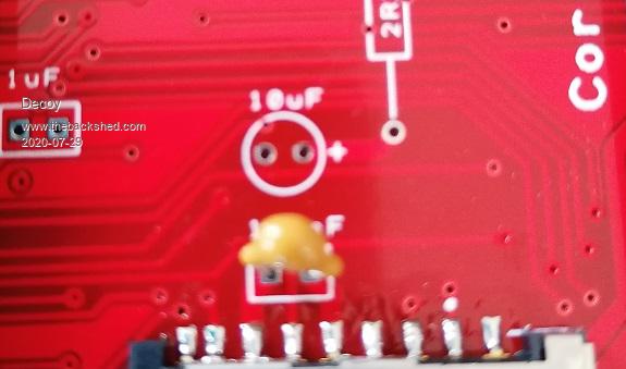 Thanks! |
||||
| Sasquatch Guru Joined: 08/05/2020 Location: United StatesPosts: 385 |
The tantalum capacitor you are showing in the photo (or at least the place where it will go) is part of a filter circuit for the power to the SD card. � Tantalum capacitors have a lower ESR (Equivalent Series Resistance) than normal electrolytic capacitors. �In simple terms, this allows them to "respond faster" to voltage changes. �A perfect capacitor would have an ESR of zero, in the real world a capacitor acts like a capacitor with a resistor in series and also a small amount of inductance in the leads and structure of the capacitor. �For a 10uf electrolytic capacitor this would be on the order of several ohms. �For the tantalum cap it might be less than one ohm of ESR. The small 100nF ceramic capacitor next to it should have an extremely low ESR (i.e. less that 0.01 ohm)� 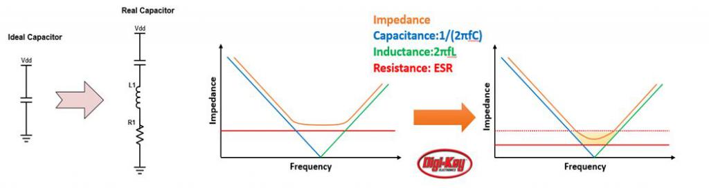 On the CMM2, this capacitor will supply power to the SD card when the power demand of the SD card "surges". �The filter circuit prevents noise from the other components on the board from reaching the SD card. �It also prevents the power demand of the SD card from feeding back and affecting other components in the system. �This is sometimes referred to as "Decoupling" or "Bypassing" Do a internet search for "ESR" for a more technical explanation. Edited 2020-07-29 06:52 by Sasquatch -Carl |
||||
| Decoy Senior Member Joined: 02/08/2019 Location: DenmarkPosts: 109 |
Thanks for that! That was a very nice explanation. So, I will wait for them to show up - and not use a electrolytic in its place :) / |
||||
| Geoffg Guru Joined: 06/06/2011 Location: AustraliaPosts: 3362 |
That capacitor is there more as a precaution. The CMM2 should run without it - if you don't want to wait. Geoff Geoff Graham - http://geoffg.net |
||||
| Sasquatch Guru Joined: 08/05/2020 Location: United StatesPosts: 385 |
Hmmmm.... given the 2.2 ohm resistor in series with the 3.3V supply to the SD card, not sure how well it would work without the 10uF capacitor? Also, there are enough builders having problems with different SD card quality etc. so probably not a great place to cut corners. The risk of damaging anything is low, so I guess it's worth a try, but I wouldn't get my hopes up about the SD card access working without the filter cap. �I haven't tried, so I can't say for sure! If you are going to try without the 10uF tantalum I would definitely jumper across the 2R2 resistor. Edited 2020-07-29 08:46 by Sasquatch -Carl |
||||
| Geoffg Guru Joined: 06/06/2011 Location: AustraliaPosts: 3362 |
Good grief Carl. I have to say that I have far more experience with Maximites than you. The resistor came from the original Colour Maximite design where it was needed to prevent the insertion of the SD card from glitching the 3.3V rail. There was no bypass cap in that design and it was not needed (there is a bypass cap already in SD cards). The resistor in the CMM2 design was included as a precaution and the two bypass caps as a further precaution against glitches. The CMM2 will run fine without the 10uF cap and you will certainly not damage anything - it is there as a precaution, nothing more. Geoff Geoff Graham - http://geoffg.net |
||||
| Sasquatch Guru Joined: 08/05/2020 Location: United StatesPosts: 385 |
Ok, I guess I'll leave the questions for the "Gurus" LOL -Carl |
||||
| KeepIS Guru Joined: 13/10/2014 Location: AustraliaPosts: 2177 |
I've had one running with a 100nf cap and no series resistor on the test CMM2 and many other devices. The commercially available populated SD card interface boards, that's the ones with a regulator and level convertors, have a 100nF bypass to stop regulator instability. The 3.3V rail in the CMM2 is already well protected and bypassed. SD card problems are not generally a result of a supply problem unless it's incredibly dirty or taking a dive at power up during the initialisation period, neither appear to be the case with the 3.3v regulator in the WS board, and your external 5v source would have to be total crap if the 3.3v volt regulator cant filter it. The risk of damaging anything without the cap is ZERO. NANO:Inverter V 8.2ks - Linux AvrDude GUI script V4.1 |
||||
| CaptainBoing Guru Joined: 07/09/2016 Location: United KingdomPosts: 2171 |
Take a look at this guy's channel. I linked one of his capacitior tutorials I use with my students - he has a really great way of explaining things. https://www.youtube.com/watch?v=WytU5uj78-4 I would encourage you to explore his channel - it will give you a head start in stuff like tantalum Vs Ceramic Vs AluFoil etc. hth h |
||||
| Decoy Senior Member Joined: 02/08/2019 Location: DenmarkPosts: 109 |
Hi guys, thanks for the input. They should be here soon (the tantalums), and I already fitted the 2.2 ohm resistor. As a bonus question, what is the purpose of the other tantalum, located at the battery holder? CaptainBoing, thanks for the link. However, Youtube is blocked in my house. I am trying to move away from 1) watching video instead of reading 2) my PCs tend to become Youtube-machines. Thanks! |
||||
TassyJim Guru Joined: 07/08/2011 Location: AustraliaPosts: 6538 |
That would be the one connected to the incoming 5V. Needed to smooth the incoming supply which could be from a noisy source. 10uF is the preferred value for USB power. Jim VK7JH MMedit |
||||
| The Back Shed's forum code is written, and hosted, in Australia. | © JAQ Software 2026 |
