
|
|
Forum Index : Microcontroller and PC projects : Understanding CMM2 ADC ' s
| Page 1 of 2 |
|||||
| Author | Message | ||||
| hitsware2 Guru Joined: 03/08/2019 Location: United StatesPosts: 738 |
I would like ( to begin with ) to simply have the screen display the voltage present on a given pin updated every 1 second . Hopefully ( from programming manual ) : 10 SETPIN nn , AIN 20 CLS 30 PRINT PIN(nn) 40 PAUSE 1000 50 GOTO 20 Would do it , but there seems ( from user manual ) much further complications ( and even different commands ) From chip description : 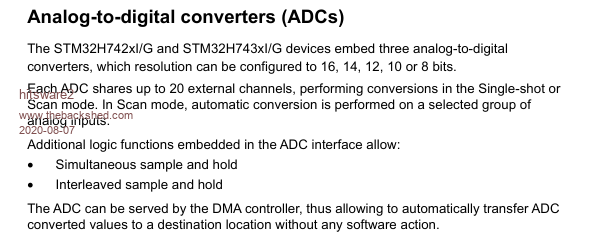 From programming manual : 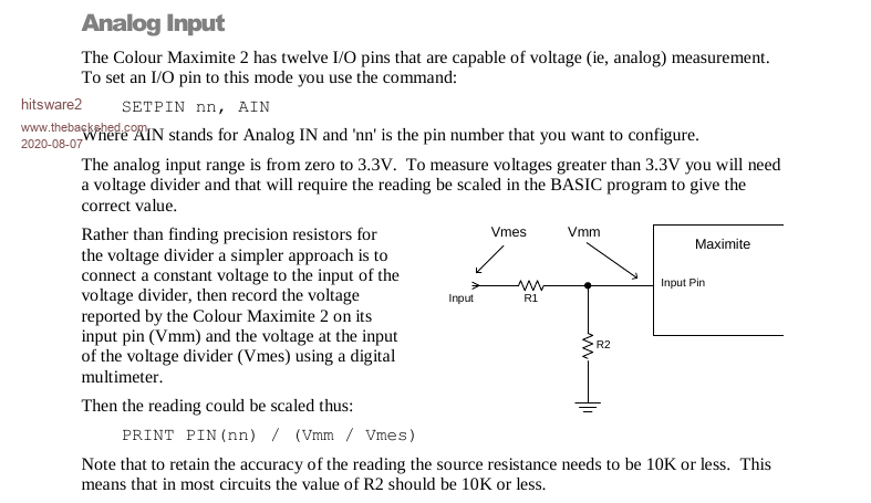 From user manual : 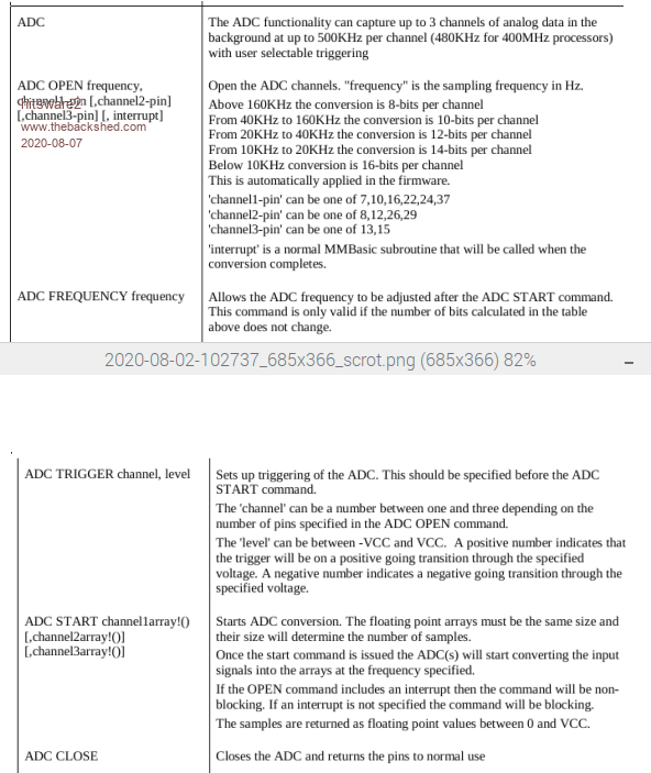 Any insight appreciated  my site |
||||
Chopperp Guru Joined: 03/01/2018 Location: AustraliaPosts: 1126 |
Your code should work fine. All I do. You would need to position the print output though on the screen. Also you need to take into account the time taken to read the sensor so your pause time will be less. In some places in programs, I wait for the seconds to change then do the readings or I use SETTICK to trigger the sensor read Using a DO LOOP SETPIN nn , AIN CLS DO PRINT PIN(nn) PAUSE 1000 LOOP ChopperP |
||||
| hitsware2 Guru Joined: 03/08/2019 Location: United StatesPosts: 738 |
Thank You ! > Also you need to take into account the time taken > to read the sensor so your pause time will be less. How much time ? I want eventually to make an oscilloscope . So it would be something like : ????? 10 SETPIN nn , AIN 20 CLS 30 FOR x = 0 TO 255 40 y = PIN ( nn ) 50 PIXEL x , y 60 NEXT x 70 GOTO 20 my site |
||||
| Chopperp Guru Joined: 03/01/2018 Location: AustraliaPosts: 1126 |
Update,I was thinking of the temperature sensors when I mentioned delay. Normal ADC read is minimal. Sorry about that. ChopperP |
||||
| hitsware2 Guru Joined: 03/08/2019 Location: United StatesPosts: 738 |
Good Oh !  my site |
||||
| KeepIS Guru Joined: 13/10/2014 Location: AustraliaPosts: 2177 |
I think you will find pixel drawing speed will limit your bandwidth to a few hundred cycles, you need to have a blanking period, something like as a simple Settick interrupt, that is unless you are going for a long persistence (more like infinite persistence) CRO tube effect, and I doubt you will get a smooth Cathode ray tube trace effect with this method. Edited 2020-08-07 11:58 by KeepIS NANO:Inverter V 8.2ks - Linux AvrDude GUI script V4.1 |
||||
TassyJim Guru Joined: 07/08/2011 Location: AustraliaPosts: 6538 |
setpin 7, ain timer = 0 for n = 1 to 1000 x = pin(7) next n print timer 1347.201 > The simple loop takes 1.3mS per loop. Most of the time is in the ADC read line. Using the simple setpin x, AIN : y = pin(x) is slow (in computer terms) It is OK for the occasional read but not the best for making a CRO That is what the ADC command is perfect for. It reads the pin in the background and fills an array for you. All in the background and bloody fast if that's what you need. The bits/resolution depends on the sampling speed you choose. You can then concentrate on doing the any maths and displaying that's required. Jim VK7JH MMedit |
||||
| hitsware2 Guru Joined: 03/08/2019 Location: United StatesPosts: 738 |
I must be missing something very basic . Say for 255 readings . Even if in the background , Still takes the same amount of reading time ( 255 readings ) only writing to the array instead of the screen . But then the array must be written to the screen ...... If for a rudimentary scope ( no math except volts to PIXEL addresses ) how is the speed gained ? my site |
||||
| hitsware2 Guru Joined: 03/08/2019 Location: United StatesPosts: 738 |
I plan to write ( pixel by pixel ) 1 ' trace ' then CLS .... my site |
||||
| KeepIS Guru Joined: 13/10/2014 Location: AustraliaPosts: 2177 |
Decided to quickly see how long it does take for 255 readings. � Using ADC 12.9us Using x=PIN(7) 372us Edit, that including drawing the basic waveform. Edited 2020-08-07 14:15 by KeepIS NANO:Inverter V 8.2ks - Linux AvrDude GUI script V4.1 |
||||
| TassyJim Guru Joined: 07/08/2011 Location: AustraliaPosts: 6538 |
How did you get 372 microseconds for "Using x=PIN(7)"? I get more like milliseconds. The time taken using ADC command will be entirely depending on the sample frequency you choose. Something I haven't tried is reading the array while it's being stored. For fast sampling, flipping between arrays and using arrays to plot is great but for slow sampling, being able to follow along behind the ADC, grabbing data a few samples behind will be an interesting idea. Jim VK7JH MMedit |
||||
| TassyJim Guru Joined: 07/08/2011 Location: AustraliaPosts: 6538 |
AS a simple demo, I have an analogue joystick connected to pin 7. The program: SETPIN 7, AIN DO CLS TIMER = 0 FOR x = 1 TO 256 y = PIN(7) PIXEL x,400-y*100, RGB(255,255,255) NEXT x TEXT 10,10,STR$(TIMER)+"mS" PAUSE 500 LOOP UNTIL INKEY$<>"" SAVE IMAGE "cheapcro.bmp" The result: 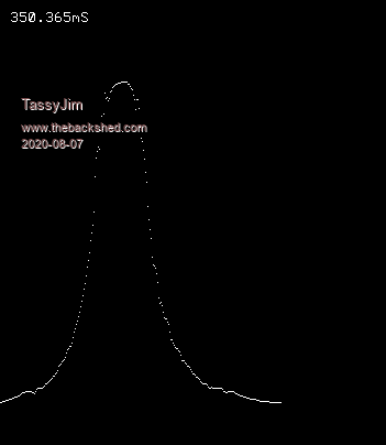 Running it without any variable input will still give you an idea if the scan rate. The 500 mS pause is there so you have time to read the output. Jim VK7JH MMedit |
||||
| KeepIS Guru Joined: 13/10/2014 Location: AustraliaPosts: 2177 |
That's strange, you said it took you 1.3ms for 1 to 1000, why should it take me longer to do essentially the same thing 255 times? NANO:Inverter V 8.2ks - Linux AvrDude GUI script V4.1 |
||||
| TassyJim Guru Joined: 07/08/2011 Location: AustraliaPosts: 6538 |
1.3mS per loop, not for the full 1000 loops 1347.201mS for 1000 Jim VK7JH MMedit |
||||
| KeepIS Guru Joined: 13/10/2014 Location: AustraliaPosts: 2177 |
Well I must have a faulty timer. NANO:Inverter V 8.2ks - Linux AvrDude GUI script V4.1 |
||||
| matherp Guru Joined: 11/12/2012 Location: United KingdomPosts: 11512 |
No-one has mentioned the impact of setting the ADC accuracy Try setpin 7,ain,16 timer=0 for i=0 to 999 a=pin(7) next i b=timer timer=0 for i=0 to 99 next i print (b-timer)/1000 then setpin 7,ain,8 timer=0 for i=0 to 999 a=pin(7) next i b=timer timer=0 for i=0 to 99 next i print (b-timer)/1000 Edited 2020-08-07 17:44 by matherp |
||||
| TassyJim Guru Joined: 07/08/2011 Location: AustraliaPosts: 6538 |
I have found something "interesting" On my Y revision board 0.702454 0.070334 On my V revision board 1.345789 0.077606 The V chip take twice as long as the Y chip when using 16bit resolution. Jim VK7JH MMedit |
||||
| hitsware2 Guru Joined: 03/08/2019 Location: United StatesPosts: 738 |
|
||||
| TassyJim Guru Joined: 07/08/2011 Location: AustraliaPosts: 6538 |
|
||||
| hitsware2 Guru Joined: 03/08/2019 Location: United StatesPosts: 738 |
> I completely forgot that you can set > the ADC bit resolution with the SETPIN command. > I should read the manual more often. Speaking of manuals ..... The ' user ' manual doesn't even mention ' AIN ' .... Unless I ' m missing it someways .... Should be not far after ' ADC ' ? my site |
||||
| Page 1 of 2 |
|||||
| The Back Shed's forum code is written, and hosted, in Australia. | © JAQ Software 2026 |
