
|
|
Forum Index : Microcontroller and PC projects : CMM2 Display Blacking Out / No Signal Found
| Author | Message | ||||
| va7ehf Newbie Joined: 23/07/2020 Location: CanadaPosts: 6 |
Hi there, I've soldered together a CMM2 from parts and I'm having an issue with the video output. One display, an old LCD TV, cannot see the VGA signal. Another display, an LCD computer monitor, sees the VGA signal but repeatedly keeps blacking out rendering it unusable. When the image is visible, the video looks great. The firmware also appears to continue running even while the display is blacking out (the machine registers key presses). There appears to be some dependence on what the firmware is doing - this never happens in the command line mode, and it is especially bad when the cursor is on the third line in the edit mode. I probed the 5V and 3V3 on an oscilloscope - looks clean and accurate. I've tried different power supplies: PCs, laptops, wall adapters. So far I can't identify any problems visually with the soldering or the components. Perhaps related: putting my thumb over the crystal pads on the Waveshare board causes the exact same symptom. Any ideas would be much appreciated. Thanks! |
||||
TassyJim Guru Joined: 07/08/2011 Location: AustraliaPosts: 6538 |
Welcome. Its a pity that things aren't going right fr you but there is hope. Some monitors are very fussy. The best fix is to do the Crystal modification. Replace the 8MHz xal with a 8MHz oscillator module. It is more stable and keeps the vast majority of monitors happy. Jim VK7JH MMedit |
||||
| Atomizer_Zero Senior Member Joined: 04/07/2020 Location: United KingdomPosts: 134 |
I had blacking out issues on my diy board too. Theres a spot under the waveshare board (on the cmm2 pcb) for the xtal ocscillator and 10uf cap, as TassyJim said. I installed these myself the other day (very fiddily) and it worked perfectly. |
||||
| Womble Senior Member Joined: 09/07/2020 Location: United KingdomPosts: 267 |
I condensed this down from my "CMM2: v3.0 PCB kit build notes thread" which is getting a bit long ... From the Construction Guide: External Oscillator The latest PCB has provision for an external 8 MHz crystal oscillator to replace the 8 MHz crystal on the Waveshare CPU board. This may be needed in some rare cases where a monitor has difficulty with some VGA modes (such as 800x600 pixel 16-bit colour). Most people will not need this mod however, if it is required, it can be implemented by removing the 8 MHz crystal on the Waveshare CPU board and installing the external oscillator and a capacitor on the motherboard. The parts required are: 1 SMD 1206 100nF ceramic capacitor 1 8MHz oscillator in 5.0 x 7.0 mm SMD package (QX7 XO 25ppm). Eg, RS Stock Nbr 813-6194 . The Parts I used: I left the crystal in place, and can confirm that this was OK for me Good luck with this, hopefully should fix your problem. Edited 2020-08-08 22:24 by Womble |
||||
| va7ehf Newbie Joined: 23/07/2020 Location: CanadaPosts: 6 |
Thanks for the advice guys! My understanding was that the external oscillator fix was for shimmering / loss of sync issues with video modes that had higher colour depth than the default. The external oscillator is definitely worth trying. However, I can't remove the CPU board because the solder has wicked up through the connector and soldered several pins down. This happened to me before and I had to throw away the motherboard and CPU board. Now I've got all the parts soldered down to the motherboard and it's too expensive to start over again. Any advice on this? This might be worth making a separate thread. |
||||
| matherp Guru Joined: 11/12/2012 Location: United KingdomPosts: 11499 |
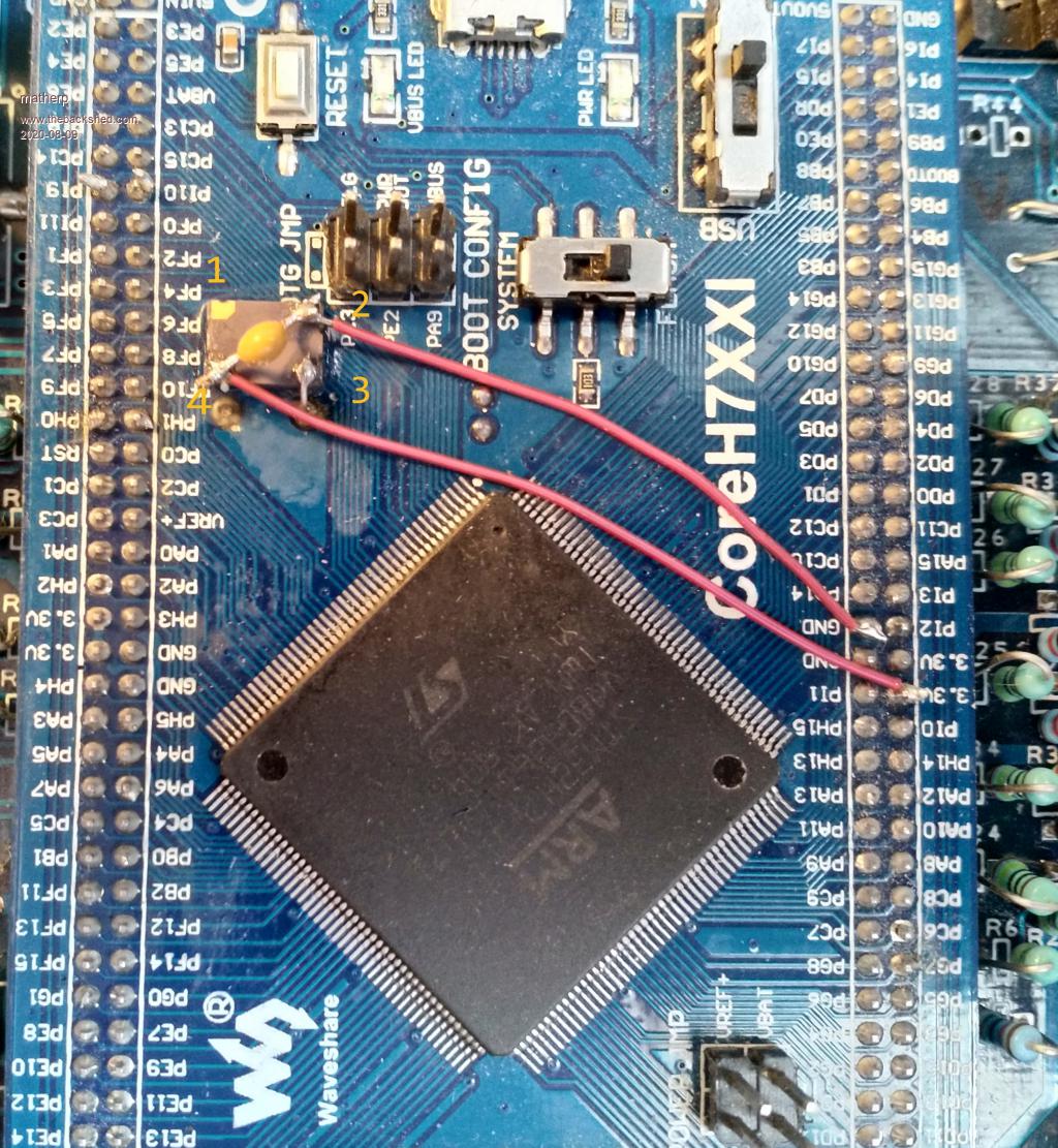 |
||||
| Womble Senior Member Joined: 09/07/2020 Location: United KingdomPosts: 267 |
Ouch  Sorry to hear that Sorry to hear thatAre you aure its soldered in place ? I find on my board the Waveshare is VERY tight in the socket and I need to gently lever it to separate the CPU and motherboard. Obviously do this with great care so as not to damage anything. |
||||
| TassyJim Guru Joined: 07/08/2011 Location: AustraliaPosts: 6538 |
I have done both my boards using the dead bug style like in Peters photo. You don't have to remove the old crystal so it can all be done without removing the Waveshare module. Jim VK7JH MMedit |
||||
| va7ehf Newbie Joined: 23/07/2020 Location: CanadaPosts: 6 |
I will have to give the dead bug fix a shot! The dead bug fix crossed my mind but I was not sure if it was necessary to remove the crystal. This is great news. Womble, I would say it's definitely soldered down. I have lifted the board out of the socket before (I later beefed up the solder joints thinking the issue was a bad joint). In the meantime, I modified the MMBasic firmware to use 640x400 as the default instead of 800x600. The CMM2 now displays correctly on the TV - I can see it occasionally shimmer, this must be when the computer monitor blacks out. The computer monitor occasionally blacks out still at 640x400. Thanks for all the suggestions everyone, it's really much appreciated. I will update here when I get the parts for the external oscillator mod. Edited 2020-08-09 08:04 by va7ehf |
||||
| Womble Senior Member Joined: 09/07/2020 Location: United KingdomPosts: 267 |
No problemo ... I was surprised at how much force was required to remove the Waveshare on my board. Quite scary amounts of force. I too have had to go over my soldering, although in my case it is to try to fix a sound fault (still unresolved). I can confirm that removeal of the Waveshare Crystal is not necessary (thankfully). Thank goodness for Dead Bugs and Bodge Wires  |
||||
| robert.rozee Guru Joined: 31/12/2012 Location: New ZealandPosts: 2528 |
va7ehf: did you resolve this problem? based on the solution for a problem that Womble was having, it may be worthwhile rechecking the 5v supply to the CMM2 again, and perhaps (even if it seems ok) swapping the USB A-B cable being used. cheers, rob :-) |
||||
CircuitGizmos Guru Joined: 08/09/2011 Location: United StatesPosts: 1427 |
This would be a nice feature to have for the distributed firmware as an OPTION. Micromites and Maximites! - Beginning Maximite |
||||
| va7ehf Newbie Joined: 23/07/2020 Location: CanadaPosts: 6 |
I am glad to say that dead-bugging the oscillator as matherp depicted fixed the issue entirely for me. My CMM2 now works at full 800x600 resolution on any display device I try it on. The fix was easy to do. Thank you everyone for your support! CircuitGizmos: The default mode is a preprocessor define in the firmware. I found zero bugs with changing the default mode with respect to the editor and file browser. I imagine it could easily be made a global variable instead. |
||||
| TassyJim Guru Joined: 07/08/2011 Location: AustraliaPosts: 6538 |
Glad it's working for you. The latest beta has an option just for this: Jim VK7JH MMedit |
||||
| The Back Shed's forum code is written, and hosted, in Australia. | © JAQ Software 2026 |
