
|
|
Forum Index : Microcontroller and PC projects : CMM2: TassyJim's 40way IO Test Program, questions ?
| Author | Message | ||||
| Womble Senior Member Joined: 09/07/2020 Location: United KingdomPosts: 267 |
Following on from the saga of building my CMM2, I thought it would be a good idea to test the IO connecter. Jim's Original Post This inspired me to break out the "Stripboard" and test the 40way IO connector on my CMM2 v3 Kit. �Rummaging in my leftover components store I came up with twenty eight 1.2K 2% resistors and the other components required to build this tester. I used this schematic: 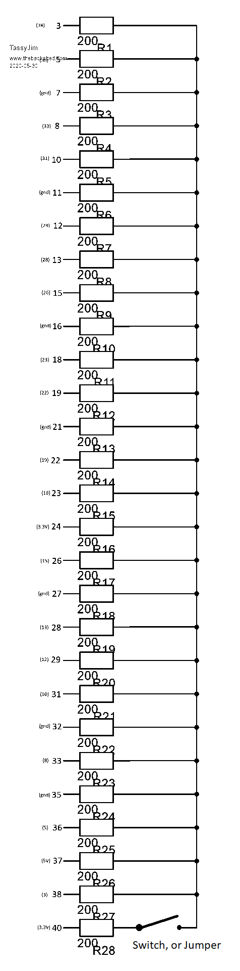 Modified from Jim's original to include the recommended switch. Jim's Program: CMM2_40way_Test.zip produced this output: 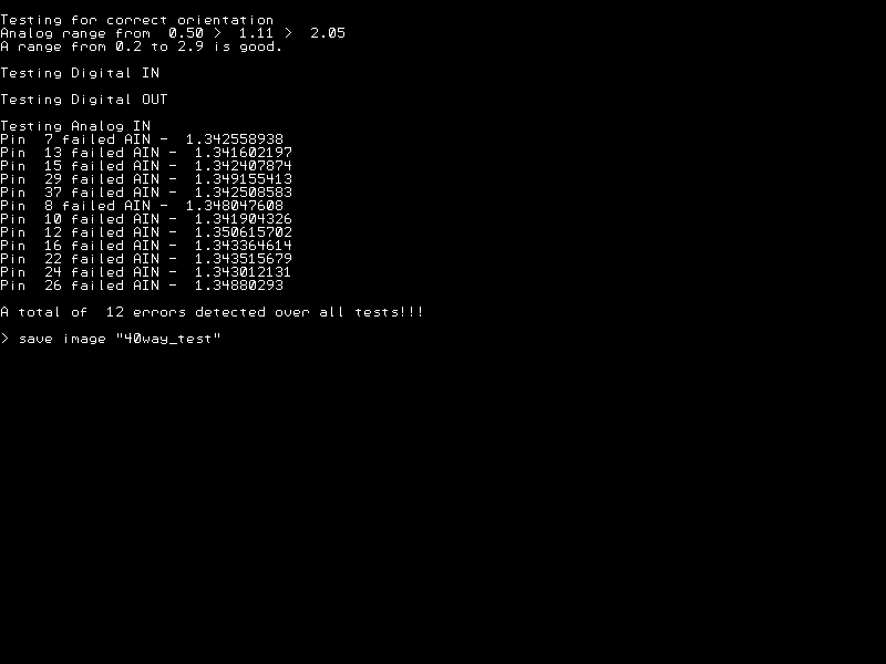 I assume this portion of the program produces the errors: � �PRINT "Testing Analog IN" � �' testing analog in. � �' set one pin high and one pin low to give VCC/2 at the common point. � �SETPIN 3, DOUT � �SETPIN 5, DOUT � �PIN(3) = 1 � �PIN(5) = 0 � � � �FOR n = 0 TO 11 � � �testpin = apins(n) � � �SETPIN testpin, AIN � � �v = PIN(testpin) � � �IF V < 1.58 OR V > 1.7 THEN PRINT "Pin ";testpin ;" failed AIN - ";v : bug = bug+1 � � �SETPIN testpin, OFF � �NEXT n � �SETPIN 3, OFF � �SETPIN 5, OFF I am getting an analog reading for V of around 1.34 - 1.35 (volts), which flags as an error. Is this because I am uisng 1.2K resistors ? As mentioned elsewhere on the forum I had some problems with my CMM2 build, so it may be that I have some poor solder joints, or have damaged my board with all the rework carried out during the troubleshooting. I find it interesting that the errors only occur with the Analog Inputs, all 12 of them. �Makes me suspect my 40way IO connector �might be fine, and my resistors are too high a value. Thoughts please, Thanks Womble Edited 2020-08-12 10:11 by Womble |
||||
| Womble Senior Member Joined: 09/07/2020 Location: United KingdomPosts: 267 |
I used 1.2K 2% resistors because I had them. They were free, wombled from an electronics lab that was closing down and given to me by a friend. |
||||
bigmik Guru Joined: 20/06/2011 Location: AustraliaPosts: 2981 |
Hi Womble, I reported similar to Jim when I started building CMM2 as all of them seemed to fail on at least one AIn by not much (ie mine were 1.57 and the test failed below 1.58) And I found that I worked around this by setting all of the IO as inputs (as opposed to OFF) and the Tests passed. It is a little bit touch and go, as there are a lot of IO in parallel that can affect the level that is actually presented (via a resistor) from the one output pin. Jim emailed me and said when he wrote the program it worked on his first board then failed similarly on subsequent boards. His fix was to adjust the Ain range to be between 1.55 and 1.75v This is basically Jim's fix code however I see your results are around 1.34 so will probably still fail.. Just before the Analog tests you will see 4 lines I added to set unused pins to Din instead of OFF status.. remove the REMs and try with that.. There is definitely a difference between Din and OFF. I used 220R for mine.. ' CMM2 pin tester. ' requires a bank of 28 same size resistors (I used 200 ohm) ' connected from each pin in pintest() array to a common point DIM pintest(27) = (3,5,7,11,13,15,19,21,23,27,29,31,33,35,37,8,10,12,16,18,22,24,26,28,32,36,38,40) DIM apins(11) = (7,13,15,29,37,8,10,12,16,22,24,26) DIM INTEGER k, bug DIM FLOAT v FOR k = 0 TO 27 ' make sure all pins are floating � SETPIN(pintest(k)), OFF NEXT k CLS ' read analog voltage with one pin gnd, all floating then one pin at 3.3V ' header wrong way around will give a narrow range of voltages ~1.16V PRINT "Testing for correct orientation" SETPIN 13, AIN SETPIN 3, DOUT PIN(3) = 0 PRINT "Analog range from ";STR$(PIN(13),2,2);" > "; SETPIN 3, OFF PRINT STR$(PIN(13),2,2);" > "; SETPIN 3, DOUT PIN(3) = 1 v = PIN(13) PRINT STR$(v,2,2) PRINT "A range from 0.2 to 2.9 is good." SETPIN 3, OFF SETPIN 13, OFF IF v < 2 THEN � PRINT "It doesn't look right!!" � PRINT "Giving up on the tests." ELSE � PRINT "Testing Digital IN" � ' toggle one pin high/low and check that each pin follows. � SETPIN 40, DOUT � FOR k = 0 TO 26 � � testpin = pintest(k) � � SETPIN testpin , DIN � � PIN(40) = 1 � � IF PIN(testpin ) <> 1 THEN PRINT "Pin ";testpin ;" failed DIN high" : bug = bug+1 � � PIN(40) = 0 � � IF PIN(testpin ) <> 0 THEN PRINT "Pin ";testpin ;" failed DIN low" : bug = bug+1 � � SETPIN testpin , OFF � NEXT k � � SETPIN 38, DOUT � testpin = 40 � SETPIN testpin , DIN � PIN(38) = 1 � IF PIN(testpin ) <> 1 THEN PRINT "Pin ";testpin ;" failed DIN high" : bug = bug+1 � PIN(38) = 0 � IF PIN(testpin ) <> 0 THEN PRINT "Pin ";testpin ;" failed DIN low" : bug = bug+1 � SETPIN testpin , OFF � SETPIN 38, OFF � � PRINT "Testing Digital OUT" � ' toggle each pin in turn and check that output follows. � SETPIN 40, DIN � FOR k = 0 TO 26 � � testpin = pintest(k) � � SETPIN testpin , DOUT � � PIN(testpin) = 1 � � IF PIN(40 ) <> 1 THEN PRINT "Pin ";testpin ;" failed DOUT high" : bug = bug+1 � � PIN(testpin) = 0 � � IF PIN(40 ) <> 0 THEN PRINT "Pin ";testpin ;" failed DOUT low" : bug = bug+1 � � SETPIN testpin , OFF � NEXT k � � SETPIN 38, DIN � testpin = 40 � SETPIN testpin , DOUT � PIN(testpin) = 1 � IF PIN(38 ) <> 1 THEN PRINT "Pin ";testpin ;" failed DOUT high" : bug = bug+1 � PIN(testpin) = 0 � IF PIN(38 ) <> 0 THEN PRINT "Pin ";testpin ;" failed DOUT low" : bug = bug+1 � SETPIN testpin , OFF � SETPIN 38, OFF � � PRINT "Testing Analog IN" ' �for k = 0 to 26 'testpin = pintest(k) ' �setpin testpin,din 'next k � ' testing analog in. � ' set one pin high and one pin low to give VCC/2 at the common point. � SETPIN 3, DOUT � SETPIN 5, DOUT � � � PIN(3) = 1 � PIN(5) = 0 � FOR n = 0 TO 11 � � testpin = apins(n) � � SETPIN testpin, AIN � � v = PIN(testpin) � � IF V < 1.55 OR V > 1.75 THEN PRINT "Pin ";testpin ;" failed AIN - ";v : bug = bug+1 � � SETPIN testpin, OFF � NEXT n � SETPIN 3, OFF � SETPIN 5, OFF � � IF bug = 0 THEN � � PRINT "All tests completed with no errors" � ELSE � � PRINT "A total of ";bug; " errors detected over all tests!!!" � ENDIF ENDIF Try deleting the comments Edited 2020-08-12 11:49 by bigmik Mick's uMite Stuff can be found >>> HERE (Kindly hosted by Dontronics) <<< |
||||
| Womble Senior Member Joined: 09/07/2020 Location: United KingdomPosts: 267 |
Thanks for your comments Mick, I will give that code a try. That was my original thought. However I didn't have enough of them, and there was this big bag of resistors which I had wombled away. So I went for 1.2K |
||||
TassyJim Guru Joined: 07/08/2011 Location: AustraliaPosts: 6538 |
I was too tight with my test for analogue. change IF V < 1.58 OR V > 1.7 THEN PRINT "Pin ";testpin ;" failed AIN - ";v : bug = bug+1 to IF V < 1.25 OR V > 1.9 THEN PRINT "Pin ";testpin ;" failed AIN - ";v : bug = bug+1 The lower the resistance value chosen, the closer the reading will be to Vcc/2 All your pins gave the same result so it is save to say they are working as expected. Jim VK7JH MMedit |
||||
| Womble Senior Member Joined: 09/07/2020 Location: United KingdomPosts: 267 |
Excellent Jim, thanks for clarifying that. My gut feeling was that they were working OK  and that the discrepancy was the resistor value I chose. and that the discrepancy was the resistor value I chose.Regards An Even Happier Womble |
||||
| bigmik Guru Joined: 20/06/2011 Location: AustraliaPosts: 2981 |
Hi Womble, All, I would be curious as to your result by removing the REMs that I marked in RED on the above listing. Kind Regards Mick Mick's uMite Stuff can be found >>> HERE (Kindly hosted by Dontronics) <<< |
||||
| Womble Senior Member Joined: 09/07/2020 Location: United KingdomPosts: 267 |
No problem. Here is the amended program I used, and the test results: CMM2_40way_Test.zip adjust the commented out code to suit. BigMik's amendment, setting pins to DIN (as shown in red in previous post) 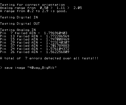 TassyJim's amendment, adjusting the voltage range deemed acceptable (1.25v - 1.9v) 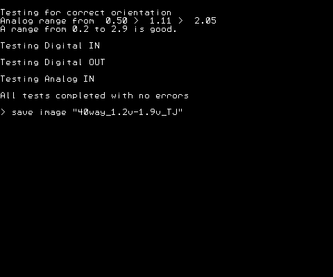 Both the amendments: 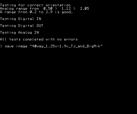 Many thanks for your help guys |
||||
| bigmik Guru Joined: 20/06/2011 Location: AustraliaPosts: 2981 |
Hi Womble, That is interesting.. Changing the SetPin to Din instead of OFF changes the reading (in your case) from 1.34v to 1.72 ish results. But as Jim says it is a rough test for analog reads.. Different resistors would read different values.. Kind Regards Mick Mick's uMite Stuff can be found >>> HERE (Kindly hosted by Dontronics) <<< |
||||
| TassyJim Guru Joined: 07/08/2011 Location: AustraliaPosts: 6538 |
Hi Mick, There are 4 10k resistors on the I2C lines pulling the voltage high. With low value resistors in the test setup, it is not very evident but with Wombles higher values, we get a significant change. Its still enough to show which pins are working. Jim VK7JH MMedit |
||||
| The Back Shed's forum code is written, and hosted, in Australia. | © JAQ Software 2026 |
