
|
|
Forum Index : Microcontroller and PC projects : cmm22 SD card socket woes
| Page 1 of 2 |
|||||
| Author | Message | ||||
Herry Senior Member Joined: 31/05/2014 Location: AustraliaPosts: 261 |
CMM2. Oh dear! ĀI think I used too much flux when soldering in the SD card socket and numerous pins are showing short to earth. I've established that the 4 large corner Āpins(left and right looking from the front) are meant to be to earth (they hold the beast), but I'm not sure of the rest of the pins on the left. How do they relate to card inserted and write protect? Should both be open circuit when no card is there? Can anyone supply a clear pinout, as used on the CMM2. (I haven't touched the rear nine pins yet in case I have to remove the card!) Edited 2020-08-13 17:50 by Herry Senior?! ĀWhatever it says, I'm a complete and utter beginner... |
||||
TassyJim Guru Joined: 07/08/2011 Location: AustraliaPosts: 6538 |
From the front. First pin is connected to ground second pin is 'write protect' third pin is 'card present' with no card present, both card detect and write protect should be open. Jim VK7JH MMedit |
||||
Grogster Admin Group Joined: 31/12/2012 Location: New ZealandPosts: 9975 |
The WP and CD pins on the socket are VERY close to the outer shield metal thing, and if you use too much solder, you will EASILY bridge them to the shield thing, which will ground them when they should not be. I use 0.38mm solder to do those pins, as too much solder is so easy to apply. This is the same solder I use to do the pins on the SRAM chip, or any other chip with 0.5mm pin spacing, as being very thin, it allows you to solder the pin(s) without much risk of bridging pins as is easily the case with 0.8mm or 1mm solder. Smoke makes things work. When the smoke gets out, it stops! |
||||
| Womble Senior Member Joined: 09/07/2020 Location: United KingdomPosts: 267 |
According to the "Construction_Guide.pdf" this is the datasheet for the SD Card Socket: Hirose 9 Way Right Angle SD Card Memory Card Connector with Solder Termination RS 502-5004 Mfr.Part DM1AA-SF-PEJ(21) I find that soaking some solder braid in liquid flux (from a flux pen) made it MUCH easier to wick away any "Solder Excesses" Close examination with a jewellers loupe or magnifying glass can help you spot those pesky bridges. |
||||
bigmik Guru Joined: 20/06/2011 Location: AustraliaPosts: 2981 |
Hi Herry, You said numerous pins short to earth, but then you say you havenÆt soldered the rear 9 pins yet.. Which pins are the ænumerousÆ ones? Barring the rear 9 the 4 corner larger ones ARE GND and physically fix the socket to the pcb.. Of the 3 tiny pins on the left hand edge (viewed from the front) one is GND and there are only two to worry about, I have to admit these can be difficult.. I use a 2.5mm 45degree chisel point and use just the point of the iron, I then touch the pad and just the tip of the pin and apply 0.5mm solder but you have to be careful not to use too much else the pin will short to the case.. I have thought of using a thin sliver of that heat proof orange tape (forgot its name) and using that to protect the edge of the case but so far I have managed without much trouble. I donÆt use flux on the connector as if it gets inside the connector it can cause reliability issues so I avoid it like the plague.. even cleaning the flux off after I use minimal flux remover and toothbrush then a clean with iso propyl. Are you in strife? Do you need assistance? I am happy to help if you need it. Just pay postage each way.. Regards, Mick Mick's uMite Stuff can be found >>> HERE (Kindly hosted by Dontronics) <<< |
||||
| robert.rozee Guru Joined: 31/12/2012 Location: New ZealandPosts: 2528 |
i have wondered how folks may get along with the various soldering on the CMM2 - of particular note the (optional) crystal oscillator and SD card socket. i'm assuming that kits will always use the waveshare module, so soldering the H7 (or should that be M7?) isn't an issue. as a backup in the case of a catastrophic failure in soldering the SD socket (of the lifted pads variety), it would be good if someone could document wiring up one of the cheap ebay SD card modules as a replacement: https://www.ebay.com/itm/193508425811 this could be wired up to the underside of the motherboard, then glued in the place where the SD socket should have resided. a small adjustment in the front panel slot would likely be needed. as a further extension of this idea, perhaps the PCB could be revised to include a 8x2 set of pads could be added to allow mounting the above module upside-down directly to the motherboard instead of the SD socket (in theory, this should not require changing the front panel slot) at the same time, a through-hole footprint could be added to allow use of a 0.3" leaded can oscillator module (if necessary, mounted to the underside of the motherboard if there is insufficient clearance between motherboard and waveshare module). cheers, rob :-) |
||||
| Womble Senior Member Joined: 09/07/2020 Location: United KingdomPosts: 267 |
Kapton Tape |
||||
| Womble Senior Member Joined: 09/07/2020 Location: United KingdomPosts: 267 |
My weapon of choice for building the CMM2 kit: 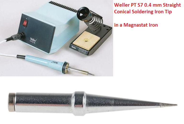 This Forum Link talks about how I soldered the optional Oscillator mod. I used a very similar technique for the Audio Socket, and the SD Card Socket. ĀBut with those items, because they have plastic locating lugs that go into holes in the pcb, and in the case of the SD card must be flush with the board, I tacked the items in place with one or two pretinned pads only. ĀThen used liquid solder from a "flux pen" and carefully solderd the others. Once I had checked that weverything was flush to the pcb. Solder wick soaked in liquid flux I found to be good for correcting errors. Once you have finished, clean the board with flux remover and a toothbrush. ĀThis helps inspection to check for errors. Hope this helps. Womble (amateur solderer) Edited 2020-08-14 00:22 by Womble |
||||
| Volhout Guru Joined: 05/03/2018 Location: NetherlandsPosts: 5931 |
Weller Magnastat...the best there is. I bought mine 40 years ago.... The S7 tip is for leaded solder. For leadfree solder use the S8 tip. But honestly, the magnastats where not designed for leadfree solder. The higher temperatures limit the lifetime. Mine only gets lead.... I am on my last tip. Haven't checked if these are still obtainable.  Edited 2020-08-14 01:30 by Volhout PicomiteVGA PETSCII ROBOTS |
||||
| Atomizer_Zero Senior Member Joined: 04/07/2020 Location: United KingdomPosts: 134 |
I have a DIY cmm2 and a pre-assembled cmm2. the DIY one shows continuity to ground with or without a sd card (whoops!), but it works perfectly fine! The assembled unit DOES NOT show continuity to ground without an sd card in. with one in, they do. The pins that do not show continuity are the 2nd and 3rd pins (the ones closer to the back of the sd card slot). Edited 2020-08-14 01:49 by Atomizer_Zero |
||||
| Womble Senior Member Joined: 09/07/2020 Location: United KingdomPosts: 267 |
Bought mine 20 years ago, couldn't afford the 24v power supply so built one using a torroidal transformer and associated components. Works brilliantly. I also only use leaded solder. Tips seem to be still available, but quite expensive (Ż5+ a pop). |
||||
| matherp Guru Joined: 11/12/2012 Location: United KingdomPosts: 11512 |
If it is just the WR pin then it is probably OK. If it is the card detect then changing cards without rebooting is going to cause bad things to happen. The code relies on the CD pin to know it has to re-initialise the card and clear its buffers |
||||
| Herry Senior Member Joined: 31/05/2014 Location: AustraliaPosts: 261 |
Thanks all for the magnificent response, and especially to bigmik for your generous repair offer. By numerous pins I was including the 4 corner pins which I then realised *should* go to earth as they are mounting pins. It is the 3 small pins on the left that I am narrowed down to, one of which I now realise is to earth. Thanks for making the actual pins clear, Tassy Jim! I have a much clearer idea now. And the problem is now how to remove the short. Thanks Womble for confirming I should use a solder wick doused in flux! ĀI'll report back later! BTW, the tone and helpfulness on this forum is streets ahead of any other I subscribe to. A great community indeed! Edited 2020-08-14 06:09 by Herry Senior?! ĀWhatever it says, I'm a complete and utter beginner... |
||||
palcal Guru Joined: 12/10/2011 Location: AustraliaPosts: 2039 |
+1 "It is better to be ignorant and ask a stupid question than to be plain Stupid and not ask at all" |
||||
| Herry Senior Member Joined: 31/05/2014 Location: AustraliaPosts: 261 |
Progress(?) report. I have been wicking out solder from pin 2 off and on all day. Still I have a short to earth but the wick is coming out stiff with solder so there's still some there. What a hassle! Senior?! ĀWhatever it says, I'm a complete and utter beginner... |
||||
| bigmik Guru Joined: 20/06/2011 Location: AustraliaPosts: 2981 |
Hi Herry, You must have a lo5 of solder there.. I would remove the connector if possible.. you mentioned you havenÆt soldered the 9 pin at the rear so heat one of the corner lugs and slide a thin scalpel blade under it do that to the other pins on the corners. I would avoid trying the blade on the other 3 pins but you should be able to heat all three and lift the connector free. Regards, Mick Mick's uMite Stuff can be found >>> HERE (Kindly hosted by Dontronics) <<< |
||||
| Herry Senior Member Joined: 31/05/2014 Location: AustraliaPosts: 261 |
There's one born every minute... and it's me Ā  (a number of years ago...)! (a number of years ago...)!I found the reason for the continual solder when trying to remove the bridge on pin 2 (write protect) [not counting corner mounting pins]. It was from solder paste which I had kept smearing on the wick! The local Jaycar had sold me solder paste instead of flux paste. D'oh. Have now applied heaps of genuine flux from a flux pen onto the wick and have tried to wick up anything left. All pins now look dry and pin 3 (card present is signalling OK) But I can't clear the short on pin 2 whatever I do, leaving the iron there for a minute or so. I must have put solder well under the card holder. Re the suggestion that I lift the card holder completely from the board to clean it up, in the interim I had soldered the rear 9 pins so looks like that makes it impractical to lift the holder. Any other ideas? I don't think I'll be using write protect so perhaps removing that line elsewhere -- line severing pin 2? -- might be an idea? What do others think? Edited 2020-08-15 12:16 by Herry Senior?! ĀWhatever it says, I'm a complete and utter beginner... |
||||
| TassyJim Guru Joined: 07/08/2011 Location: AustraliaPosts: 6538 |
'Write protect' is open with no card or WP set to 'protect' With it shorted to ground, you should be OK. It is the CD one that is important. Jim VK7JH MMedit |
||||
| Herry Senior Member Joined: 31/05/2014 Location: AustraliaPosts: 261 |
Thanks Jim. So all I lose is the ability to signal write protect? CD? Card present? Senior?! ĀWhatever it says, I'm a complete and utter beginner... |
||||
| TassyJim Guru Joined: 07/08/2011 Location: AustraliaPosts: 6538 |
Yes, life isn't so difficult after all. Jim VK7JH MMedit |
||||
| Page 1 of 2 |
|||||
| The Back Shed's forum code is written, and hosted, in Australia. | © JAQ Software 2026 |
