
|
|
Forum Index : Microcontroller and PC projects : Russian deluxe version of the CMM2
| Page 1 of 3 |
|||||
| Author | Message | ||||
| MauroXavier Guru Joined: 06/03/2016 Location: BrazilPosts: 303 |
Searching on the YouTube for any CMM2 new videos I found this little surprise. This is not my project and I saw this now, I�m not responsible about it and don�t have any contact with the creator, but it appears very interesting! This is a little YouTube video about it I think to make it be perfect only needs to have a mouse port with some controller onboard. |
||||
CircuitGizmos Guru Joined: 08/09/2011 Location: United StatesPosts: 1421 |
Polish perhaps? It has a sea-of-holes like the RetroMax: 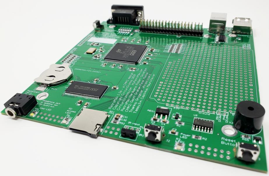 But a bigger case: 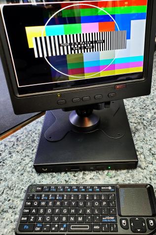 Micromites and Maximites! - Beginning Maximite |
||||
| matherp Guru Joined: 11/12/2012 Location: United KingdomPosts: 8569 |
Rob What is U5? |
||||
| CircuitGizmos Guru Joined: 08/09/2011 Location: United StatesPosts: 1421 |
Part of the power-on circuitry. The power is a button. Push once for on, again for off. The CircuitGizmos RetroMax is functionally the same as the Color Maximite 2, except there are some changes and additions: - Different board shape/size appropriate for the optional enclosure - Board mounting holes for VESA 100mm back-of-monitor mounting - Power button that toggles on/off - Reset available from front panel - IR receiver behind translucent window (on case) - Micro SD card holder - Firmware reflash button available on side - Additional "User LED" in white - Piezo "User Buzzer" - Two Nunchuk connections for two game players - PCB connection for optional real-time clock - PCB sea-of-holes for user hardware, conducive to Arduino shields - Mounting holes and orientation for Raspberry Pi HATS Edited 2020-10-11 04:13 by CircuitGizmos Micromites and Maximites! - Beginning Maximite |
||||
| matherp Guru Joined: 11/12/2012 Location: United KingdomPosts: 8569 |
Looks good  |
||||
| CircuitGizmos Guru Joined: 08/09/2011 Location: United StatesPosts: 1421 |
See this thread for the RetroMax introduction. http://www.thebackshed.com/forum/ViewTopic.php?FID=16&TID=12912 Micromites and Maximites! - Beginning Maximite |
||||
| JoOngle Regular Member Joined: 25/07/2020 Location: SwedenPosts: 82 |
Very interesting indeed. Now this one is much more In-Line with what I had in mind for the CMM2 Enclosure with the keyboard, and joystick / Nunchuck ports for multiple players. |
||||
| mclout999 Guru Joined: 05/07/2020 Location: United StatesPosts: 430 |
Go check it out. Nice guy that chated with me about his project at length. He is now looking to add a mouse option based on the threads here on the subject. https://sklep.pslabs.pl/Colour-Maximite-2-Deluxe-Edition-p146 Its big but it has a lot going for it including that joystick port right up front. |
||||
| mkopack73 Senior Member Joined: 03/07/2020 Location: United StatesPosts: 261 |
Gotta say there's some REALLY nice things in that Polish version... Love the 3 Nunchuck ports on the front, love that the Pi header is both internal and on the back and labeled.. Love that the power switch goes in the right direction ;) DB9 Joystick port is questionable. Do like that the Retromax has the Arduino pinout available, and the built in piezo buzzer. Each has their merits! |
||||
| MauroXavier Guru Joined: 06/03/2016 Location: BrazilPosts: 303 |
Oops, I thought it was Russian, it's a Polish project ... My fault. |
||||
| siwypiotr Senior Member Joined: 18/08/2020 Location: PolandPosts: 127 |
Good morning everyone. My name is Piotr Siwy and Im creator Colour Maximite 2 Deluxe Edition. I did not expected my short video will be discussed here, Im very happy that people are interested in my work. Here is pinout of the DB9 joystick port, I have used one of the forum users suggestions: https://www.thebackshed.com/forum/ViewTopic_mobile.php?TID=12282&P=3 DB9 FUNC -> GPIO 1 UP -> 35 2 DOWN ->36 3 LEFT -> 38 4 RIGHT -> 40 5 - 6 BUT A ->32 7 +5v 8 GND 9 BUT B ->33 If You have any questions please ask, I will be very happy to answer. |
||||
| siwypiotr Senior Member Joined: 18/08/2020 Location: PolandPosts: 127 |
Here You can find more pictures: 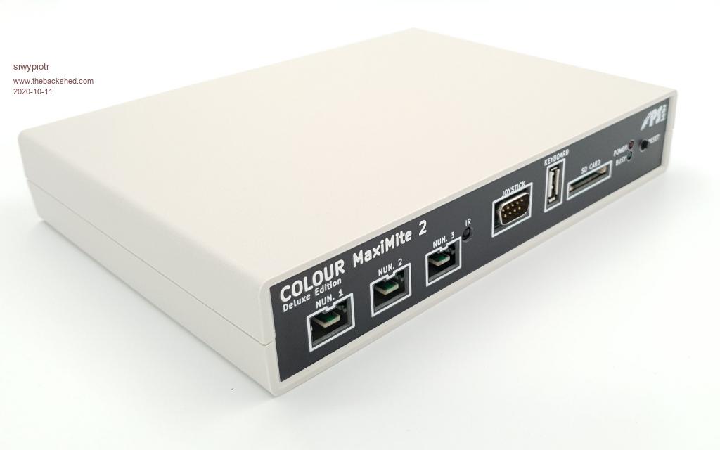 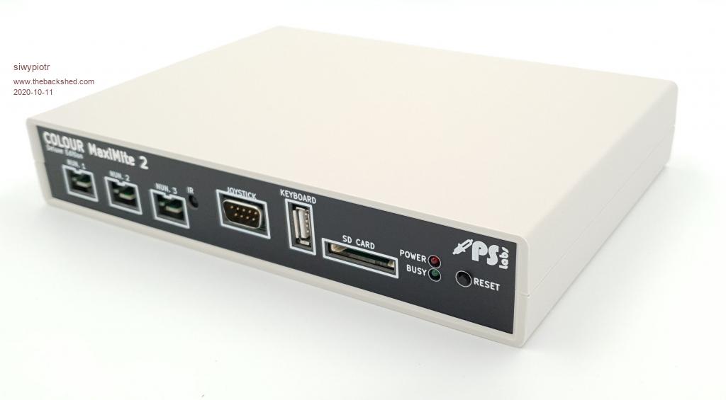 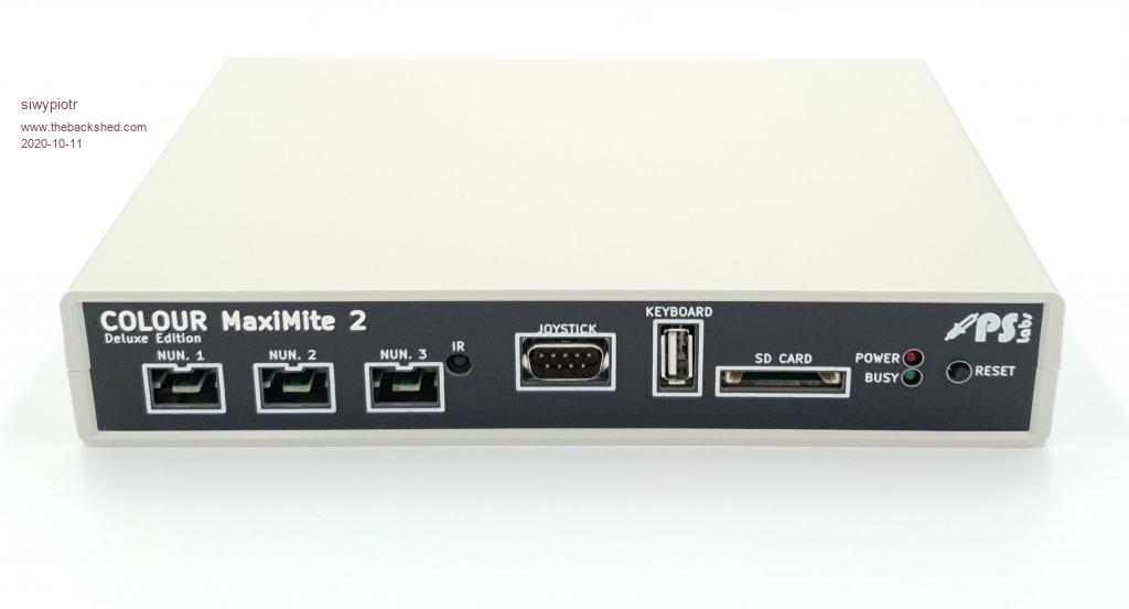 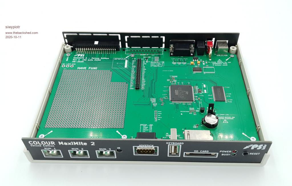 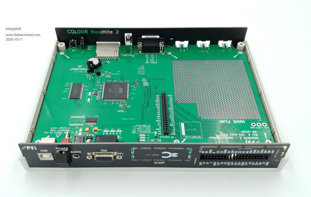 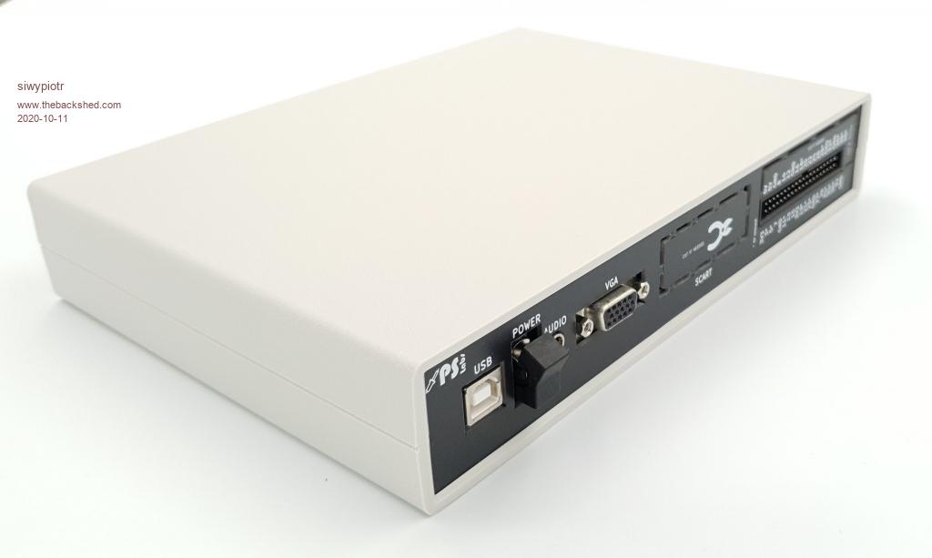 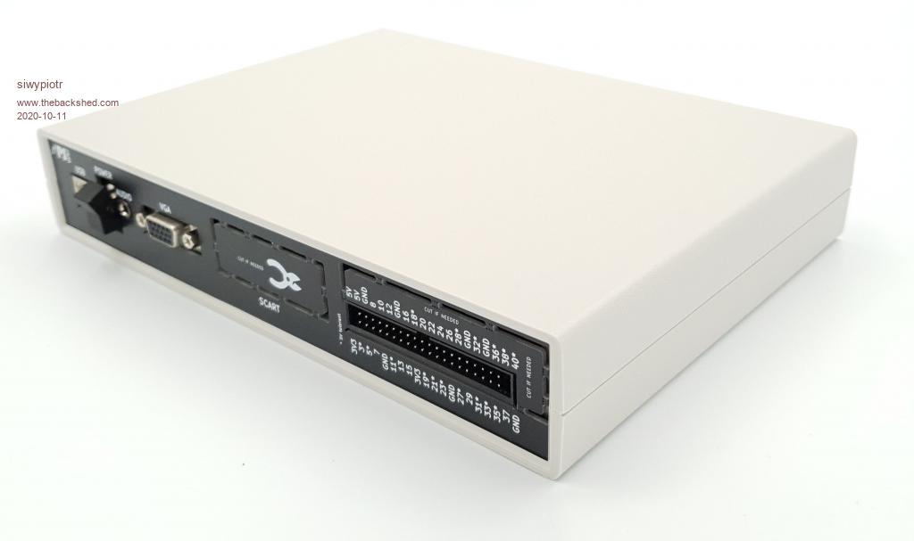 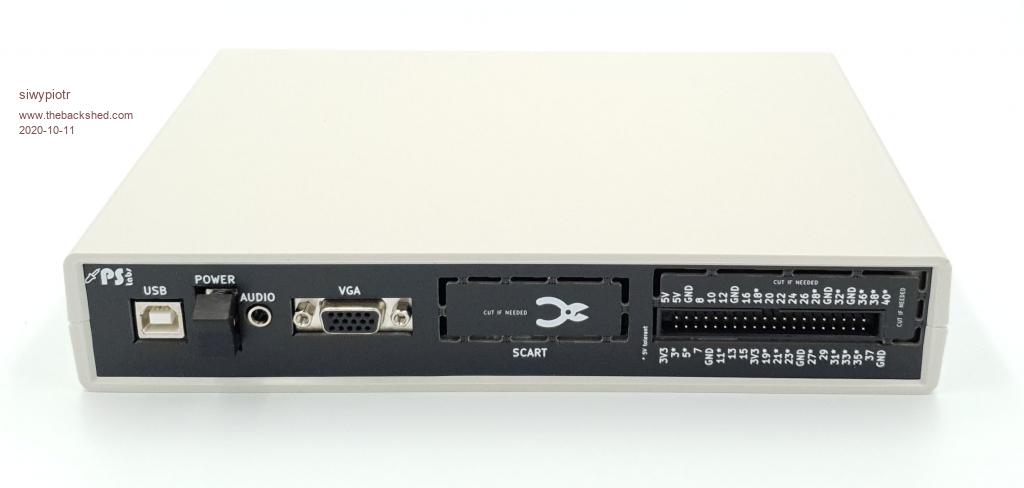 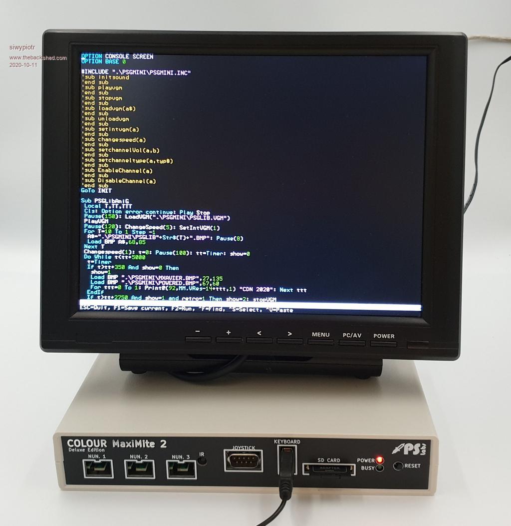 |
||||
| JoOngle Regular Member Joined: 25/07/2020 Location: SwedenPosts: 82 |
Now replace the box with...   ...and keep the PCB design, and we're getting somewhere :) |
||||
| mkopack73 Senior Member Joined: 03/07/2020 Location: United StatesPosts: 261 |
Do you ship to the USA? And does that price include the case? |
||||
| siwypiotr Senior Member Joined: 18/08/2020 Location: PolandPosts: 127 |
Yes we ship to USA. Unit is 127 USD, include the case, SD card, charging cable, fully assembled and tested. Unfortunately shipment to USA is not the cheapest 69 USD there can be also custom duties on arrival. Payment can be done via PayPal or bank transfer. Orders can be placed via email: biuro@pslabs.pl Edited 2020-10-11 20:59 by siwypiotr |
||||
| mclout999 Guru Joined: 05/07/2020 Location: United StatesPosts: 430 |
I like the prototyping section on this one. He is considering adding one of the mouse options from forums to his design but if you get one now, you or he could just add the circuitry for it on the prototype section and use the SCART cut out to add the port. he could maybe sell a small PCB and wiring instructions. I think this is the best part of the design. The rest is very nice too. |
||||
| siwypiotr Senior Member Joined: 18/08/2020 Location: PolandPosts: 127 |
It is not a problem to add mouse support on next version. I can do it by adding additional STM microcontroller with USB support and send data to main processor using i2c or other protocol. But I do not want to create additional standard, creators of the firmware have to agree how it should be done and I will follow their standard. Edited 2020-10-12 17:08 by siwypiotr |
||||
| robert.rozee Guru Joined: 31/12/2012 Location: New ZealandPosts: 2285 |
do all three (or two, in the case of the CG RetroMax) nunchuk sockets simply have the clock and data lines paralleled up? given that the nunchuk interface is I2C, it seems that a good method of adding a mouse interface - or indeed an interface for any other relatively slow-speed device - would be to simply use an I2C address not used by any nunchuk and hang the (polled only) interface off the existing nunchuk bus. this should provide 100% compatibility between the various CMM2 implementations without creating incompatibility. this approach would also mean that none of the pins on the 40-way connector are tied up, while allowing for the addition of some number of extra devices to the CMM2. each device could be talked to via a C-function, or if widely adopted then geoff and/or peter may be willing to add support into the mmbasic firmware at some future time. if one was worried about swamping the nunchuk I2C bus, consider this: what are the chances of anyone wanting to use a nunchuk at the same time as a mouse? cheers, rob :-) |
||||
| siwypiotr Senior Member Joined: 18/08/2020 Location: PolandPosts: 127 |
Mouse topic is continued on this forum: https://www.thebackshed.com/forum/ViewTopic.php?PID=156812#156812 |
||||
| CircuitGizmos Guru Joined: 08/09/2011 Location: United StatesPosts: 1421 |
For the CG RetroMax Nunchuk port 1 is I2C #3 and Nunchuk port 2 is I2C #1. Micromites and Maximites! - Beginning Maximite |
||||
| Page 1 of 3 |
|||||
