
|
|
Forum Index : Microcontroller and PC projects : Circuit advice
| Page 1 of 2 |
|||||
| Author | Message | ||||
lew247 Guru Joined: 23/12/2015 Location: United KingdomPosts: 1709 |
I need an output from a Pic pin to switch the shutdown on a buck converter that converts 3.3 to 5V If the Shutdown pin on the buck converter is below 0.4V the buck converter is switched off if the pin is high the converter switches on I'm making a circuit that needs 3.3V from the pic easy enough but it also needs 5V for a different ic and it's being powered from batteries so the current draw needs to be as low as possible, ie the converter only turned on when needed Should this circuit work? it's only to switch the Shutdown pin on THIS module 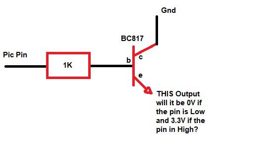 |
||||
| Turbo46 Guru Joined: 24/12/2017 Location: AustraliaPosts: 1693 |
I don't think so. You need a converter configuration with a pull-up resistor. If the PIC has a 5 volt compliant pin a direct connection should be OK. Bill Keep safe. Live long and prosper. |
||||
| Sasquatch Guru Joined: 08/05/2020 Location: United StatesPosts: 385 |
Well, No! The data sheet specifies that the power converter module has a 100K pull-up resistor on the shutdown input. Assuming that your Pic is running at 3.3V, you will need the collector of the NPN transistor tied to +3.3V and move the 1K resistor to connect the emitter to ground. �then your shutdown signal would be connected at the junction of the emitter and resistor as in your diagram. � � � � � �� � � � +3.3v � � � � � � � � � � �| � � � � � � � � � � /c � � � � � � � � b|/ Pic Pin -----| � �NPN � � � � � � � � � |\ � � � � � � �� � � �\e � � � � � � � �� � �|--- shutdown � � � � � � � �� � �\ � � � � � � �� � � �/ � � � � � � � �� � �\ 1K � � � � � � � �� � �/ � � � � � � �� � � �| � � � � � � �� � � Gnd Edit: �Well my diagram got mangled, but you get the idea. Edited 2020-10-31 08:30 by Sasquatch -Carl |
||||
| Sasquatch Guru Joined: 08/05/2020 Location: United StatesPosts: 385 |
The spec says �< 0.4V, I don't know if a OC output would reliably take the signal low enough? �Would need to check the specs on the PIC Also need to consider the state of the pic output when uninitialized would likely result in the converter being on. Edited 2020-10-31 08:46 by Sasquatch -Carl |
||||
| Sasquatch Guru Joined: 08/05/2020 Location: United StatesPosts: 385 |
Or you could eliminate the NPN transistor if you are using a push-pull output with a 5K resistor to ground. -Carl |
||||
| Turbo46 Guru Joined: 24/12/2017 Location: AustraliaPosts: 1693 |
I would be very surprised if a PIC output could not reliably pull 100k down to below 0.4v. This is the circuit I meant. 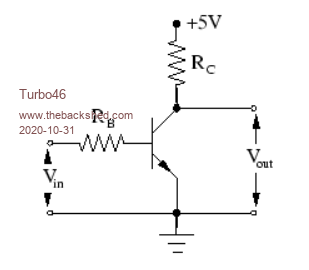 Use 100k for RB and you can omit RC if the inverter has a pullup resistor on board. If not a 100k resistor would do. Any small signal NPN transistor will do the job. An active pull down for a logic 0 is far better than using a resistor divider. But a straight connection to a 5v compliant pin is just so simple. Bill Keep safe. Live long and prosper. |
||||
| twofingers Guru Joined: 02/06/2014 Location: GermanyPosts: 1761 |
Sorry, I would expect 0.6-07V. Or? Michael causality ≠ correlation ≠ coincidence |
||||
| Turbo46 Guru Joined: 24/12/2017 Location: AustraliaPosts: 1693 |
From a datasheet: 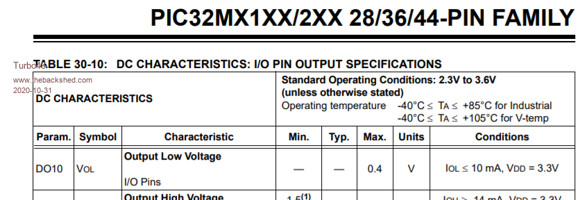 That's for 10mA not a few uA. Bill Keep safe. Live long and prosper. |
||||
| twofingers Guru Joined: 02/06/2014 Location: GermanyPosts: 1761 |
opps, I thought you meant V-out from the transistor.  causality ≠ correlation ≠ coincidence |
||||
| Turbo46 Guru Joined: 24/12/2017 Location: AustraliaPosts: 1693 |
I'd still expect 0.1 to 0.2 volts or there-about from a saturated small signal transistor at that current. Bill Keep safe. Live long and prosper. |
||||
| twofingers Guru Joined: 02/06/2014 Location: GermanyPosts: 1761 |
@Bill I think you are right! I was confused. But is it clear that the circuit inverses the voltage? That means: OUT is LOW when IN is HIGH (>0.6V). Edited 2020-10-31 10:44 by twofingers causality ≠ correlation ≠ coincidence |
||||
| hitsware2 Guru Joined: 03/08/2019 Location: United StatesPosts: 738 |
http://www.csgnetwork.com/transistorcalc.html my site |
||||
| Turbo46 Guru Joined: 24/12/2017 Location: AustraliaPosts: 1693 |
Thank you Michael. I perhaps should have made that clear. I did mean to type inverter and not converter on my first post. But hopefully a direct connection to a 5v compliant pin is all that is required. Bill @Hitsware2, That circuit could work but it relies on the transistor being open circuit when the input is low and R2 pulling the input to the buck converter low. But when the input is high the base current drawn from the PIC would be high and the voltage at the base of the transistor would only be approximately 2.8 volts (3.3v-0.7v) maybe not enough to enable the buck converter. Thank you for the interesting site. Edited 2020-10-31 12:06 by Turbo46 Keep safe. Live long and prosper. |
||||
| Sasquatch Guru Joined: 08/05/2020 Location: United StatesPosts: 385 |
The only problem with the inverter circuit would be that the connected device would be ON until the pic turned it OFF. I would assume that it would be desirable to have the connected device be OFF until the PIC starts up and turns in ON. -Carl |
||||
bigmik Guru Joined: 20/06/2011 Location: AustraliaPosts: 2981 |
Hi Lew, All, You might not get the output low enough using an NPN transistor, if not try a PNP transistor as per this cct 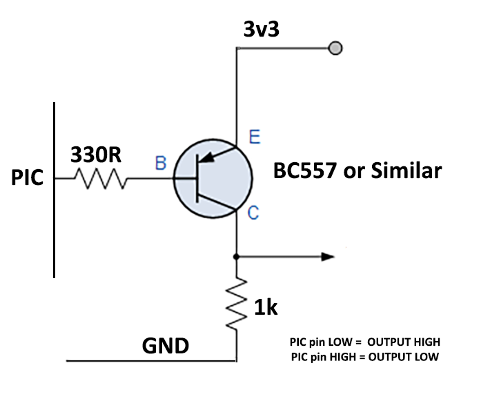 It was mentioned that there is a 100k pullup on the buck convertor so the 1k on output should pull that pin LOW when the PIC output pin is HIGH. When the PIC pin is LOW the 3v3 volts (HIGH) should get switched through to the output. If you need the buck convertor ON or OFF when the PIC is not powered you might need a pull up or pull down at the PIC pin Kind Regards Mick Mick's uMite Stuff can be found >>> HERE (Kindly hosted by Dontronics) <<< |
||||
| Sasquatch Guru Joined: 08/05/2020 Location: United StatesPosts: 385 |
The old joke comes to mind: "Ask 4 engineers and you'll get 5 opinions!" -Carl |
||||
| lew247 Guru Joined: 23/12/2015 Location: United KingdomPosts: 1709 |
Apologies I completely messed up in the first post It should have said Micromite pin (actually Armite), not pic I'd been looking at numerous microprocessors during the day and my mind went to mush I'm wondering if I could drive that pin low by directly connecting it to the Armite pin (with a capacitor across it) Edited 2020-10-31 20:05 by lew247 |
||||
| MustardMan Senior Member Joined: 30/08/2019 Location: AustraliaPosts: 175 |
Suggest a FET... I was scared of them until I dived in and found out how they work, and what cautions you need to apply (ie: ESD), but for what you want to do that is what I would use. Cheers, |
||||
| Turbo46 Guru Joined: 24/12/2017 Location: AustraliaPosts: 1693 |
I don't know why you would want a capacitor but if you have a 5 volt compliant pin then that's all you need. Bill Keep safe. Live long and prosper. |
||||
| CaptainBoing Guru Joined: 07/09/2016 Location: United KingdomPosts: 2171 |
+1 |
||||
| Page 1 of 2 |
|||||
| The Back Shed's forum code is written, and hosted, in Australia. | © JAQ Software 2026 |
