
|
|
Forum Index : Microcontroller and PC projects : The Great Colour Maximite 2 Octahedron Prize Challenge
| Author | Message | ||||
| elk1984 Senior Member Joined: 11/07/2020 Location: United KingdomPosts: 228 |
Congrats! All the maths stuff is well beyond me, but the prospect of Elite on the CMM moves a bit closer  |
||||
| vegipete Guru Joined: 29/01/2013 Location: CanadaPosts: 1128 |
Excellent start. However, the face normal looks mathematically backwards if positive is to be outward. Something needs to flip. Could be (1st point - 2nd point) and (1st point - 3rd point) Or (1st - 2nd), (2nd - 3rd) Visit Vegipete's *Mite Library for cool programs. |
||||
| matherp Guru Joined: 11/12/2012 Location: United KingdomPosts: 10195 |
Think it is correct. The greater the Z the further away. Face 3 has positive Z therefore -ve normal so don't display |
||||
| vegipete Guru Joined: 29/01/2013 Location: CanadaPosts: 1128 |
For the given coordinates, face 3 has vertices at: (0,250,0) (250,0,0) (0,0,250) Centroid at (83.33, 83.33, 83.33) seems correct. The outward normal should be (positive,positive,positive), which is pointing away from the origin. The face normal is unrelated to the viewer. The angle between the viewing direction and the face normal determines visibility, but your initial data makes no reference to viewing position/direction. This image is orthogonal projection, not perspective. I'm quite sure I have my axis orientation correct for normal right handed geometry. The translation to flipped screen coordinates (since positive y is down on the screen) must be done with care. 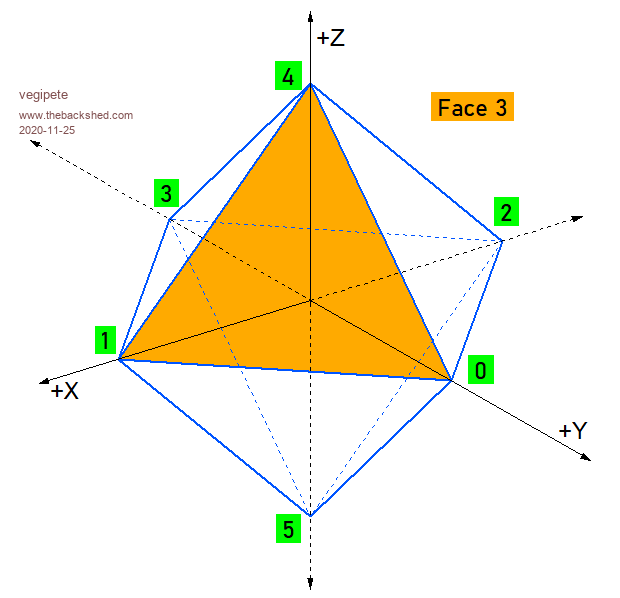 Visit Vegipete's *Mite Library for cool programs. |
||||
| LeoNicolas Guru Joined: 07/10/2020 Location: CanadaPosts: 503 |
Hey Peter I'm sorry, today I didn't have time to check your rendering data. |
||||
| matherp Guru Joined: 11/12/2012 Location: United KingdomPosts: 10195 |
I'm making progress with the 3D engine. The code for defining a 3d object is all up and working as is a basic display mechanism. ĀI'm going to be doing all the rotation using quaternions and have implemented a new MATH sub-command MATH Q_EULER yaw, pitch, roll, q(). This is in the latest beta (b6) and converts the angles (Radians but you can use OPTION ANGLE) into a rotation quaternion. With the camera facing the object yaw is looking from the top of the object and rotates clockwise, pitch rotates the top away from the camera and roll rotates around the z-axis clockwise. Have a play if you have time. Now the question for my 3D guru team: Up until now we have assumed the camera is looking along the z-axis and the viewplane is at constant z. However, I want to be able to define the yaw angle and pitch angle of the camera away from the z-axis (roll probably a step too far in processing terms). In both cases it means the viewplane needs to be orthogonal to the camera angle so is no longer orthogonal to z Can anyone point me at the math needed to do the projection from the object to the 2D representation on this tilted viewplane? Thanks guys Edited 2020-11-26 23:49 by matherp |
||||
| vegipete Guru Joined: 29/01/2013 Location: CanadaPosts: 1128 |
The roll/pitch/yaw step gets applied at the projection stage and is simple enough. Indeed, I was looking at rotating the octahedron this way early on. Here is an earlier version of my code. (Face drawing was not working right at this point, as you'll see when you run it.) On the left is the view of a fixed wireframe octahedron as the viewer moves around it. The magic math can be seen on lines 83 to 87 and the subroutine 'project'. If you compare the subroutines 'project' and 'project2', you can see the difference between the viewer fixed on the z-axis and the viewer moving around. For the fixed viewer, the view angles are theta=90 and phi=0. Phi is the angle from the +Z axis, theta from the +X axis, counter-clockwise positive. Note: when you are sitting on the z-axis, a theta rotation looks the same as roll. 'Gimbal lock', I think. Change line 84 to "phi = 0" to see this. Roll could be handled the same way at the same time, by taking the (x,y) of a given projected vertex and performing a simple point rotate. The slight gotcha is the relative direction: if the viewer rolls counter-clockwise, the view rolls clockwise. xn = x*cos(roll angle) - y*sin(roll angle) yn = x*sin(roll angle) + y*cos(roll angle) mode 1,8 timer = 0 '====================================== size = 250 d = 800 Ā Ā' distance to view plane rho = 1000 Ā Ā' distance to object (center) theta = 0 '0.3 Ā' angle around z-axis to viewer phi = 0 '1.3 Ā Ā' angle down from 'north' to viewer cx = MM.HRES/2 cy = MM.VRES/2 s1 = sin(theta) : s2 = sin(phi) c1 = cos(theta) : c2 = cos(phi) dim c(7)=(&hFF0000,&h00FF00,&h0000FF,&hFFFF00,&hFF00FF,&h00FFFF,&hFFFFFF,&h404040) dim octopath(13) dim octavert(5,3) dim rotavert(5,5) : dim rotatemp(5,5) dim faces(7,2) math set 0, rotavert() restore octashape ' read in 6 vertices for j = 0 to 5 Āread octavert(j,0) : rotavert(j,0) = octavert(j,0) Āread octavert(j,1) : rotavert(j,1) = octavert(j,1) Āread octavert(j,2) : rotavert(j,2) = octavert(j,2) next j math scale octavert(), size, octavert() math scale rotavert(), size, rotavert() ' read in vertex path to form octohedron for j = 0 to 12 Āread octopath(j) next j ' read in faces for j = 0 to 7 Āread faces(j,0) Āread faces(j,1) Āread faces(j,2) next j ' build rotation matrix ct = cos(rad(2)) : st = -sin(rad(2)) dim xrot(5,5) math set 0, xrot() xrot(0,0) = 1 xrot(1,1) = ct xrot(1,2) = -st xrot(2,1) = st xrot(2,2) = ct xrot(3,3) = 1 ct = cos(rad(1)) : st = -sin(rad(1)) dim yrot(5,5) math set 0, yrot() yrot(0,0) = ct yrot(0,2) = st yrot(1,1) = 1 yrot(2,0) = -st yrot(2,2) = ct yrot(3,3) = 1 ct = cos(rad(.5)) : st = -sin(rad(.5)) dim zrot(5,5) math set 0, zrot() zrot(0,0) = ct zrot(0,1) = st zrot(1,0) = -st zrot(1,1) = ct zrot(2,2) = 1 zrot(3,3) = 1 dim trot(5,5) ' total rotation matrix - order matters math scale xrot(),1,trot() math m_mult trot(),yrot(),xrot() Ā' use xrot() as temp storage math m_mult xrot(),zrot(),trot() for iter = 1 to 720 Ācls Ā'======================================== Ā' draw fixed object, rotating viewer Ātheta = rad (iter / 2) Ā' theta and phi are the angles of the viewer from the origin Āphi = theta / 2 Ās1 = sin(theta) : s2 = sin(phi) Āc1 = cos(theta) : c2 = cos(phi) Āx = octavert(octopath(0),0) Āy = octavert(octopath(0),1) Āz = octavert(octopath(0),2) Āproject Āfor j = 1 to 12 Ā Ābx = sx Ā Āby = sy Ā Āx = octavert(octopath(j),0) Ā Āy = octavert(octopath(j),1) Ā Āz = octavert(octopath(j),2) Ā Āproject Ā Āline bx-200,by,sx-200,sy Ānext j Ā'======================================== Ā' draw rotating object, fixed viewer Āmath m_mult trot(),rotavert(),rotatemp() Āmath scale rotatemp(),1,rotavert() Ā Ā' copy data back to main array Āfor j = 0 to 7 Ā' 8 faces, 3 vertices each Ā Āx = rotavert(faces(j,0),0) Ā Āy = rotavert(faces(j,0),1) Ā Āz = rotavert(faces(j,0),2) Ā Āproject2 Ā Ātx1 = sx Ā Āty1 = sy Ā Āx = rotavert(faces(j,1),0) Ā Āy = rotavert(faces(j,1),1) Ā Āz = rotavert(faces(j,1),2) Ā Āproject2 Ā Ātx2 = sx Ā Āty2 = sy Ā Āx = rotavert(faces(j,2),0) Ā Āy = rotavert(faces(j,2),1) Ā Āz = rotavert(faces(j,2),2) Ā Āproject2 Ā Ā Ā Āa1 = atan2(ty2 - ty1 , tx2 - tx1) Ā Āa2 = atan2( sy - ty1 , Āsx - tx1) Ā Āif a1 > a2 then Ā Ā Ātriangle tx1+200,ty1,tx2+200,ty2,sx+200,sy,c(j),c(j) Ā Āendif Ānext j Ā'======================================== Āprint @(0,0) theta, iter Āfor j = 0 to 5 Ā Ā? "vertex:" j, rotavert(j,0), rotavert(j,1), rotavert(j,2) Ānext j ' Āpause 20 Ādo : loop until inkey$ <> "" next iter end sub project Āxe = - x * s1 + y * c1 Āye = - x * c1 * c2 - y * s1 * c2 + z * s2 Āze = - x * s2 * c1 - y * s2 * s1 - z * c2 + rho Āsx = d * xe / ze + cx Āsy = cy - d * ye / ze end sub sub project2 Āxe = - x Āye = - y Āze = - z + rho Āsx = d * xe / ze + cx Āsy = cy - d * ye / ze end sub octashape: ' vertices Ā Ā0 Ā Ā Ā1 Ā Ā Ā 2 Ā Ā Ā 3 Ā Ā Ā4 Ā Ā Ā5 data Ā Ā Ā Ā0,1,0, 1,0,0, -1,0,0, 0,-1,0, 0,0,1, 0,0,-1 'data Ā0,0,1, 1,0,0, 0,1,0, -1,0,0, 0,-1,0, 0,0,-0.5 ' edge chain data Ā1,0,2,3,1,4,0,5,2,4,3,5,1 ' faces data Ā4,2,3, 4,3,1, 4,1,0, 4,0,2 data Ā5,3,2, 5,1,3, 5,0,1, 5,2,0 Edited 2020-11-27 05:44 by vegipete Visit Vegipete's *Mite Library for cool programs. |
||||
| vegipete Guru Joined: 29/01/2013 Location: CanadaPosts: 1128 |
Have some fun with this one. keys: w/x - pitch up/down a/d - yaw left/right j/k - roll left/right (I'm not sure what up/down and left/right means, but you get the idea.) mode 1,8 timer = 0 '====================================== size = 250 d = 800 Ā Ā' distance to view plane rho = 1000 Ā Ā' distance to object (center) theta = 0 '0.3 Ā' angle around z-axis to viewer phi = 0 '1.3 Ā Ā' angle down from 'north' to viewer cx = MM.HRES/2 cy = MM.VRES/2 dim octopath(13) dim octavert(5,3) dim rotavert(5,5) : dim rotatemp(5,5) dim faces(7,2) math set 0, rotavert() restore octashape ' read in 6 vertices for j = 0 to 5 Āread octavert(j,0) : rotavert(j,0) = octavert(j,0) Āread octavert(j,1) : rotavert(j,1) = octavert(j,1) Āread octavert(j,2) : rotavert(j,2) = octavert(j,2) next j math scale octavert(), size, octavert() math scale rotavert(), size, rotavert() ' read in vertex path to form octohedron for j = 0 to 12 Āread octopath(j) next j ' read in faces for j = 0 to 7 Āread faces(j,0) Āread faces(j,1) Āread faces(j,2) next j theta = 0 phi = 0 roll = 0 do Ācls Ā'======================================== Ā' draw fixed object, rotating viewer Ā' theta, phi and roll are the angles of the viewer from the origin Āprint @(0,0) "Roll: ", roll Āprint "Pitch:", phi Āprint "Yaw: Ā", theta Ās1 = sin(rad(theta)) : c1 = cos(rad(theta)) Ās2 = sin(rad(phi)) Ā : c2 = cos(rad(phi)) Ās3 = sin(rad(roll)) Ā: c3 = cos(rad(roll)) Āx = octavert(octopath(0),0) Āy = octavert(octopath(0),1) Āz = octavert(octopath(0),2) Āproject Āfor j = 1 to 12 Ā Ābx = sx Ā Āby = sy Ā Āx = octavert(octopath(j),0) Ā Āy = octavert(octopath(j),1) Ā Āz = octavert(octopath(j),2) Ā Āproject Ā Āline bx,by,sx,sy Ānext j Ā'======================================== Ādo : k$ = inkey$ : loop until k$ <> "" Āselect case k$ Ā Ācase "w" Ā Ā' pitch up Ā Ā Āphi = phi + 2 : if phi > 360 then phi = phi - 360 Ā Ācase "x" Ā Ā' pitch down Ā Ā Āphi = phi - 2 : if phi < Ā 0 then phi = phi + 360 Ā Ācase "a" Ā Ā' yaw left Ā Ā Ātheta = theta + 2 : if theta > 360 then theta = theta - 360 Ā Ācase "d" Ā Ā' yaw right Ā Ā Ātheta = theta - 2 : if theta < Ā 0 then theta = theta + 360 Ā Ācase "j" Ā Ā' roll left Ā Ā Āroll = roll + 2 : if roll > 360 then roll = roll - 360 Ā Ācase "k" Ā Ā' roll right Ā Ā Āroll = roll - 2 : if roll < Ā 0 then roll = roll + 360 Āend select loop end sub project ' pitch and yaw Āxe = - x * s1 + y * c1 Āye = - x * c1 * c2 - y * s1 * c2 + z * s2 Āze = - x * s2 * c1 - y * s2 * s1 - z * c2 + rho ' project to plane Ātx = d * xe / ze Āty = d * ye / ze Ā ' 2D roll, shift to screen center Āsx = (tx * c3 - ty * s3) + cx Āsy = cy - (tx * s3 + ty * c3) end sub sub project2 Āxe = - x Āye = - y Āze = - z + rho Āsx = d * xe / ze + cx Āsy = cy - d * ye / ze end sub octashape: ' vertices Ā Ā0 Ā Ā Ā1 Ā Ā Ā 2 Ā Ā Ā 3 Ā Ā Ā4 Ā Ā Ā5 data Ā Ā Ā Ā0,1,0, 1,0,0, -1,0,0, 0,-1,0, 0,0,1, 0,0,-1 'data Ā0,0,1, 1,0,0, 0,1,0, -1,0,0, 0,-1,0, 0,0,-0.5 ' edge chain data Ā1,0,2,3,1,4,0,5,2,4,3,5,1 ' faces data Ā4,2,3, 4,3,1, 4,1,0, 4,0,2 data Ā5,3,2, 5,1,3, 5,0,1, 5,2,0 Edited 2020-11-27 06:27 by vegipete Visit Vegipete's *Mite Library for cool programs. |
||||
| vegipete Guru Joined: 29/01/2013 Location: CanadaPosts: 1128 |
The previous program often turns you inside out when you loose track of near and far, given the wireframe drawing. Here is another rendition, this time with solid faces - ie, hidden line removal. There's an extra command, "t", which toggles face and vertex labeling on and off. w/x, a/d and j/k are the same as before - lower case! I was quite pleased with myself, this code worked first time.  For reference, based on the vertex coordinates, the center of the octahedron is at (0,0,0) and vertex 0 is in the direction of +Y vertex 1 is in the direction of +X vertex 2 is in the direction of -X vertex 3 is in the direction of -Y vertex 4 is in the direction of +Z vertex 5 is in the direction of -Z mode 1,8 : cls '====================================== size = 250 d = 800 ' distance to view plane rho = 1000 ' distance to object (center) theta = 0 ' angle around z-axis to viewer phi = 0 ' angle down from 'north' to viewer roll = 0 ' roll angle around line of sight cenx = MM.HRES/2 ceny = MM.VRES/2 X = 0 : Y = 1 : Z = 2 ' used to access array index toggle = 0 dim octavert(5,2) ' 6 octahedron vertices - 3D dim projvert(5,1) ' 6 vertices projected onto viewing plane - 2D dim faces(7,2) ' 8 faces dim vertvis(5) ' visibility flags for labeling restore octashape ' read in 6 vertices for j = 0 to 5 read octavert(j,X) : read octavert(j,Y) : read octavert(j,Z) next j math scale octavert(), size, octavert() ' read in faces for j = 0 to 7 read faces(j,0) : read faces(j,1) : read faces(j,2) next j do cls '======================================== ' draw fixed object, rotating viewer ' theta, phi and roll are the angles of the viewer from the origin print @(0,0) "Roll: ", roll print "Pitch:", phi print "Yaw: ", theta s1 = sin(rad(theta)) : c1 = cos(rad(theta)) s2 = sin(rad(phi)) : c2 = cos(rad(phi)) s3 = sin(rad(roll)) : c3 = cos(rad(roll)) math set 0, vertvis() ' mark all not visible to start project6 ' project all vertices for j = 0 to 7 ' draw faces ' pull out projected x,y of three corners of tiangular face x0 = projvert(faces(j,0),X) : y0 = projvert(faces(j,0),Y) x1 = projvert(faces(j,1),X) : y1 = projvert(faces(j,1),Y) x2 = projvert(faces(j,2),X) : y2 = projvert(faces(j,2),Y) ' test for visibility if (x0-x1)*(y0-y2)<(x0-x2)*(y0-y1) then triangle x0,y0,x1,y1,x2,y2,&hFFFFFF,0 ' draw face ' label faces and vertices? if toggle then text (x0+x1+x2)/3,(y0+y1+y2)/3,str$(j),"CM",,,rgb(green) ' label face vertvis(faces(j,0)) = 1 ' mark these vertvis(faces(j,1)) = 1 ' 3 vertices vertvis(faces(j,2)) = 1 ' as visible - for labeling endif endif next j ' label visible vertices if toggle then for j = 0 to 5 if vertvis(j) then text projvert(j,X)+5,projvert(j,Y)+5,str$(j),"LT",,,rgb(red) ' label vertex endif next j endif '======================================== do : k$ = inkey$ : loop until k$ <> "" select case k$ case "w" ' pitch up phi = phi + 2 : if phi > 360 then phi = phi - 360 case "x" ' pitch down phi = phi - 2 : if phi < 0 then phi = phi + 360 case "a" ' yaw left theta = theta + 2 : if theta > 360 then theta = theta - 360 case "d" ' yaw right theta = theta - 2 : if theta < 0 then theta = theta + 360 case "j" ' roll left roll = roll + 2 : if roll > 360 then roll = roll - 360 case "k" ' roll right roll = roll - 2 : if roll < 0 then roll = roll + 360 case "t" ' toggle labels on/off toggle = toggle = 0 end select loop end '======================================== sub project6 for i = 0 to 5 xe = - octavert(i,X) * s1 + octavert(i,Y) * c1 ye = - octavert(i,X) * c1 * c2 - octavert(i,Y) * s1 * c2 + octavert(i,Z) * s2 ze = - octavert(i,X) * s2 * c1 - octavert(i,Y) * s2 * s1 - octavert(i,Z) * c2 + rho tx = d * xe / ze ty = d * ye / ze projvert(i,X) = (tx * c3 - ty * s3) + cenx projvert(i,Y) = ceny - (tx * s3 + ty * c3) next i end sub '======================================== octashape: ' vertices 0 1 2 3 4 5 data 0,1,0, 1,0,0, -1,0,0, 0,-1,0, 0,0,1, 0,0,-1 ' faces data 4,2,3, 4,3,1, 4,1,0, 4,0,2 data 5,3,2, 5,1,3, 5,0,1, 5,2,0 Visit Vegipete's *Mite Library for cool programs. |
||||
| LeoNicolas Guru Joined: 07/10/2020 Location: CanadaPosts: 503 |
I'm implementing a code with camera position and orientation, it's not ready yet. I'm a little busy and I'm not having a lot of time to work on it  |
||||
| PeteCotton Guru Joined: 13/08/2020 Location: CanadaPosts: 543 |
I feel your pain. I've been trying to find some Maximite time for myself, but between work and an excruciating hangover from my daughter's 21st birthday party (our province just went in to lockdown - so me and her sisters had to step in as drinking buddies), it's not got the love it deserves. Hopefully this weekend! |
||||
| matherp Guru Joined: 11/12/2012 Location: United KingdomPosts: 10195 |
Guys It would be great if you could find time to have a play with the attached hack version CMM2V1.5.zip 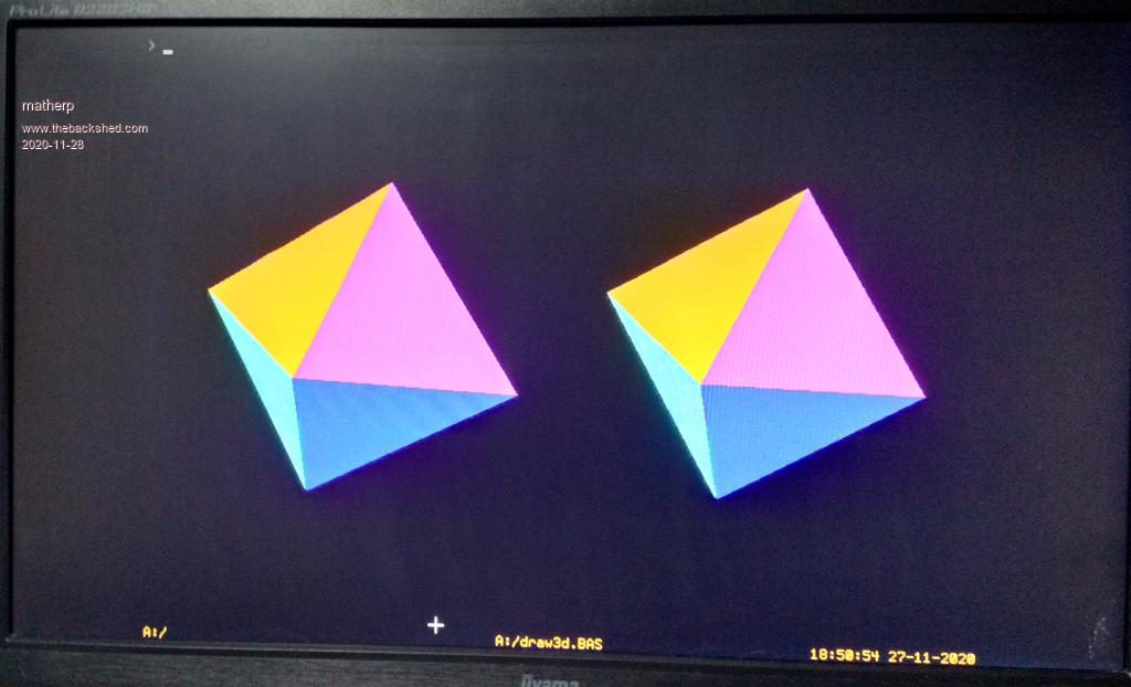 This has the start of the 3D engine. The four commands implemented so far should be obvious from the example program option explicit option default float dim integer camera_y = mm.vres-20 dim integer viewplane = 700 dim integer camera_z = 0 dim integer camera_x dim integer c timer=0 dim q(4) dim yaw=rad(1),pitch=rad(2),roll=rad(0.5) dim integer nv=6, nf=8 ' octahedron has 6 vertices and 8 faces 'array to hold vertices dim v(2,nv-1)=(0,250,0, Ā 250,0,0, Ā -250,0,0, Ā0,-250,0, Ā 0,0,250, Ā 0,0,-250) ' array to hold number of vertices for each face dim integer fc(nf-1) =(3, 3, 3, 3, 3, 3, 3, 3) dim integer bcol(nf-1)=(rgb(red),rgb(blue),rgb(green),rgb(magenta),rgb(yellow),rgb(cyan),rgb(brown),rgb(gray)) dim integer fcol(nf-1)=(0,0,0,0,0,0,0,0) 'array to hold vertices for each face dim integer fv(math(sum fc())-1)=(0,5,2, Ā0,1,5, Ā0,2,4, Ā0,4,1, Ā3,2,5, Ā3,5,1, Ā3,1,4, Ā 3,4,2 ) gui cursor on 1,40,camera_y ' create 3D object number 1 draw3d create 1, nv, nf, v(), fc(), fv(),bcol(),bcol() ' create 3D object number 2 draw3d create 2, nv, nf, v(), fc(), fv(),bcol(),bcol() page write 1 for c=0 to 720 Ācamera_x=c+40 Ādraw3d camera 1,viewplane,camera_x,camera_y,camera_z Ādraw3d camera 2,viewplane,camera_x,camera_y,camera_z Ādraw3d show 1,mm.hres\4,mm.vres\2,1000 Ādraw3d show 2,mm.hres\4*3,mm.vres\2,1000 Āmath q_euler yaw,pitch,roll,q() Ādraw3d rotate 1,q() Ādraw3d rotate 2,q() Āinc yaw,rad(1) Āinc pitch,rad(2) Āinc roll,rad(0.5) Āgui cursor camera_x,camera_y Āpage copy 1 to 0,b Ādo while inkey$="":loop next print timer draw3d close all It easily wins the challenge when configured appropriately but in the example I single step by pressing any key. Each iteration rotates the two octahedron and also moves the camera position. At the moment the SHOW command just clears the minimum area where the object was previously displayed. The bit I'm not confident in is the 2D rendering dependent on camera position but it seems to do the right sort of thing. The tricky bit was getting the face ordering. The firmware sorts the faces by the dot product of the normal vector and the ray and that seems to give the correct order. Otherwise with different camera positions there are faces that are correctly not hidden but shouldn't show. Note that there is a camera position associated with with each object so that different views can be shown simultaneously but currently the same object can't be shown in different places, although, as in the example the same meta-data can easily be used for multiple objects. Object rotation is deliberately separated from showing the object so that you can move the object round the screen separately from changing its orientation Edited 2020-11-28 05:13 by matherp |
||||
| vegipete Guru Joined: 29/01/2013 Location: CanadaPosts: 1128 |
Here is yet another version of the viewer moving around the fixed object. Commands: (lower case) 1/2/3 - select object: tetrahedron, octahedron, icosahedron t - toggle vertex/face labeling on and off j/k - viewer roll w/x - 'pitch', more like latitude, except angle is measured down from north pole a/d - 'yaw', more like longitude i/m - zoom in and out - distance from origin u/n - move view plane near and far, effect is like field of view: lower number is greater field of view, which accentuates perspective distortion. y/b - simultaneous zoom and view plane in and out So what is left? A viewer in 3D space has 6 degrees of freedom: 3 degrees (x,y,z) specify where the viewer is in space, 2 more (pitch,yaw) specify which direction the viewer is looking and a final one (roll) specifies rotation around the line of sight. This program sort of inverts the frame of reference, constraining the viewer to look at a certain point (the origin) while allowing freedom to move in the other 4 of the 6 dimensions. Solid3DViewerMove.zip Visit Vegipete's *Mite Library for cool programs. |
||||
| vegipete Guru Joined: 29/01/2013 Location: CanadaPosts: 1128 |
Interesting. I am still wrapping my head around what I am seeing. Something tells me that with appropriate optics, feeding each image to each eye would give a true 3D view of the octahedron. I take it that: - camera_x/y/z is the location of the camera, - SHOW parameters 2,3,4 are the location of the center of the object. By commenting out lines 26 and 40, the face drawing can sort-of be experienced. This shows more faces are being drawn than is necessary, although some sort of painter's algo is saving it. But is this over-complicating things? I'm able to determine face visibility _after_ projection. Do you see, in the fullness of time, the ability to extract data back out of the DRAW3D data structures? If you consider the last 2 programs I posted above, I can label faces and vertices because I can access the 2D projected vertex coordinates. (Not that it matters at this stage but DRAW3D commands are not colour coded in the editor. Neither are the GUI commands.) Visit Vegipete's *Mite Library for cool programs. |
||||
| PeteCotton Guru Joined: 13/08/2020 Location: CanadaPosts: 543 |
Can you confirm if the engine will handle planes with 4 vertices? I was playing with the Elite ship (of course  ), and when I create the model with some 4 vertice planes they get distorted (image on right below), but the same model using only 3 vertice planes (image on left) is fine (apart from the missing gaps of course). ), and when I create the model with some 4 vertice planes they get distorted (image on right below), but the same model using only 3 vertice planes (image on left) is fine (apart from the missing gaps of course).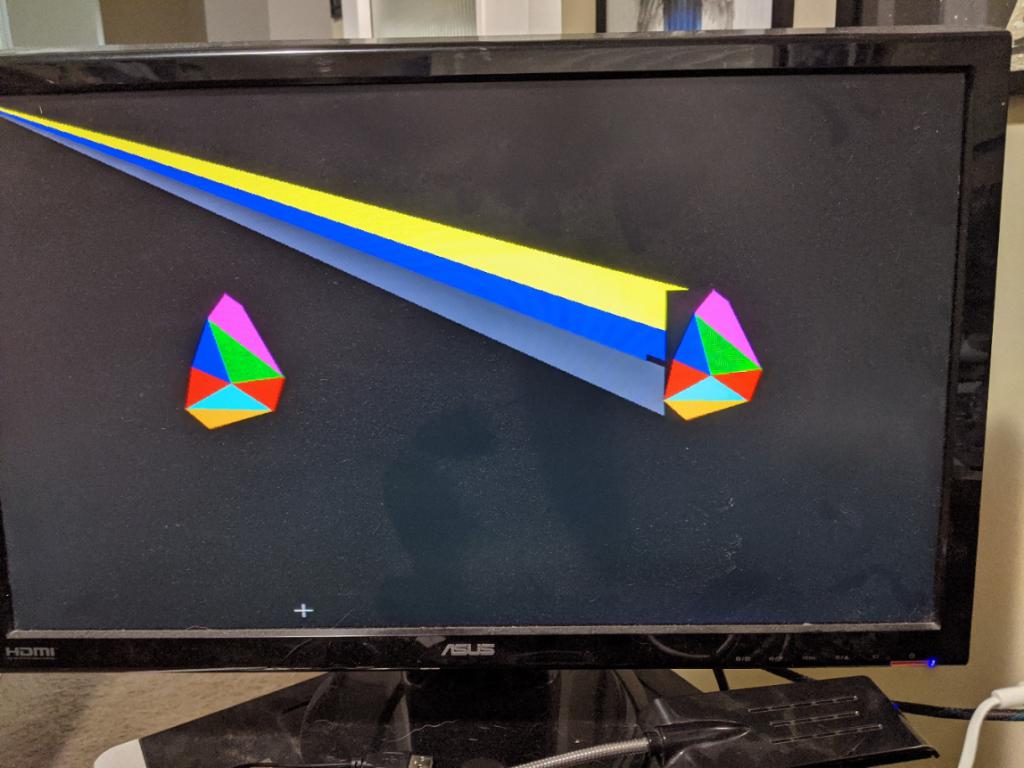 Of course, it absolutely could be my code. But I thought I'd better check in case it hadn't been implemented yet. As a side note: To save me having to recreate the same Elite ship every time, I started working on a rudimentary object file format (emulated by READ/DATA commands for the time being), that would allow me to load the object definitions in as needed. option explicit option default float dim integer camera_y = mm.vres-20 dim integer viewplane = 700 dim integer camera_z = 0 dim integer camera_x dim integer c,t,s timer=0 dim q(4) dim yaw=rad(1),pitch=rad(2),roll=rad(0.5) ' Octohedron ' Vertices data "VP",0,250,0, 250,0,0, -250,0,0, 0,-250,0, 0,0,250, 0,0,-250 ' Vertice points data "VC",3, 3, 3, 3, 3, 3, 3, 3 ' Vertice Counts ' Face colours data "FC", rgb(red),rgb(blue),rgb(green),rgb(magenta),rgb(yellow),rgb(cyan),rgb(brown),rgb(gray) ' Face definitions data "FD",0,5,2, 0,1,5, 0,2,4, 0,4,1, 3,2,5, 3,5,1, 3,1,4, 3,4,2 data "END" ReadObject (1,6,8) ' Elite ship with some 4 point planes ' Vertices data "VP",32,0,76, -32,0,76, 0,26,24, -120,-3,-8, 120,-3,-8, -88,16,-40 ' Vertice points data 88,16,-40, 128,-8,-40, -128,-8,-40, 0,26,-40, -32,-24,-40, 32,-24,-40 data "VC",3, 4,3,3,4,3,3,4,3,3,3,3,3,3,4,4,3 ' Vertice Counts ' Face colours data "FC", rgb(red),rgb(blue),rgb(green),rgb(magenta),rgb(yellow),rgb(cyan),rgb(brown),rgb(gray) data rgb(red),rgb(blue),rgb(green),rgb(magenta),rgb(yellow),rgb(cyan),rgb(brown),rgb(gray), rgb(red) ' Face definitions data "FD",2,1,0, 0,1,10,11, 6,2,0, 0,4,6, 7,4,0,11, 1,2,5, 5,3,1, 1,3,8,10, 9,5,2 data 2,6,9, 3,5,8, 7,6,4, 10,8,5, 11,7,4, 9,10,8,5, 9,6,7,11, 9,11,10 data "END" ReadObject (2,12,17) ' Elite ship with 3 point planes ' Vertices data "VP",32,0,76, -32,0,76, 0,26,24, -120,-3,-8, 120,-3,-8, -88,16,-40 ' Vertice points data 88,16,-40, 128,-8,-40, -128,-8,-40, 0,26,-40, -32,-24,-40, 32,-24,-40 data "VC",3, 3,3,3,3,3,3,3,3,3,3,3,3,3,3,3,3 ' Vertice Counts ' Face colours data "FC", rgb(red),rgb(blue),rgb(green),rgb(magenta),rgb(yellow),rgb(cyan),rgb(brown),rgb(gray) data rgb(red),rgb(blue),rgb(green),rgb(magenta),rgb(yellow),rgb(cyan),rgb(brown),rgb(gray), rgb(red) ' Face definitions data "FD",2,1,0, 0,1,10, 6,2,0, 0,4,6, 7,4,0, 1,2,5, 5,3,1, 1,3,8, 9,5,2 data 2,6,9, 3,5,8, 7,6,4, 10,8,5, 11,7,4, 9,10,8, 9,6,7, 9,11,10 data "END" ReadObject (3,12,17) gui cursor on 1,40,camera_y page write 1 for c=0 to 720 camera_x=c+40 draw3d camera 3,viewplane,camera_x,camera_y,camera_z draw3d camera 2,viewplane,camera_x,camera_y,camera_z draw3d show 3,mm.hres\4,mm.vres\2,1000' draw3d show 2,mm.hres\4*3,mm.vres\2,1000 math q_euler yaw,pitch,roll,q() draw3d rotate 3,q() draw3d rotate 2,q() inc yaw,rad(1) inc pitch,rad(2) inc roll,rad(0.5) gui cursor camera_x,camera_y page copy 1 to 0,b ' do while inkey$="":loop next page write 0 print 720000/timer draw3d close all end sub ReadObject(objNum as integer, verticeCount as integer, faceCount as integer) local string checkSum local integer t local float v(2,verticeCount-1) read checkSum if checksum <> "VP" then print "Cannot find start of object #", str$(objNum), " vertices (VP). Value found:", checkSum for t=0 to verticeCount-1 for s=0 to 2 read v(s,t) next s next t read checkSum if checksum <> "VC" then print "Cannot find start of object #", str$(objNum), " vertice count (VC). Value found:", checkSum local integer fc(faceCount-1) for t=0 to faceCount-1 read fc(t) next t read checkSum if checksum <> "FC" then print "Cannot find start of object #", str$(objNum), " face colours (FC). Value found:", checkSum local integer bcol(faceCount-1) for t=0 to faceCount-1 read bcol(t) next t read checkSum if checksum <> "FD" then print "Cannot find start of object #", str$(objNum), " face definitions (FD). Value found:", checkSum local integer fv(math(sum fc())-1) for t=0 to math(sum fc())-1 read fv(t) next t read checkSum if checksum <> "END" then print "END of object #", str$(objNum), " not found" draw3d create objNum, verticeCount, faceCount, v(), fc(), fv(),bcol(),bcol() end sub |
||||
| matherp Guru Joined: 11/12/2012 Location: United KingdomPosts: 10195 |
4, 5, 6, 7.... in theory but not tested. Any convex shape where the vertices are listed clockwise. Not sure what you mean. There seem to be planes that are pointing towards the camera so will not be hidden by the "normal" mechanism that still won't show because of Painters. This doesn't occur with the camera directly in front of the object but does when the camera is offset. If I run the code without Painters I get incorrect displays even when filtering for the dot-product |
||||
| vegipete Guru Joined: 29/01/2013 Location: CanadaPosts: 1128 |
The shapes so far are convex. (various 'hedrons, the space ship I think.) That means that any face towards the camera must be completely visible. Visit Vegipete's *Mite Library for cool programs. |
||||
| PeteCotton Guru Joined: 13/08/2020 Location: CanadaPosts: 543 |
I just built a square out of 4 triangles (2 for each side of the object), and it works fine (left hand side of image below). And using the same data tried to do sides with 4 vertices and got the same issue (the 4th point appears to default to screen co-ords 0,0) (right hand side of image below). Note: 3D models appear to require a minimum of 4 faces, is that correct? You could in theory have a single faced object if you are doing a wall.  Edited 2020-11-28 09:33 by PeteCotton |
||||
| matherp Guru Joined: 11/12/2012 Location: United KingdomPosts: 10195 |
This is stretching my 3D visualisation. The problem I'm trying to solve at the moment is 3D objects that are off the camera viewing axis. So the current code only supports the camera looking along the z-axis and tries to apply correct perspective for a 3D object that is not directly in front of the camera. I think that in this case the act of projection can effectively "hide" faces that are pointing towards the camera and therefore some sorting of drawing order is needed but it is very difficult to demonstrate and I could be completely wrong. Once I have sorted this projection issue and the multi-sided issue then next step is to look at rotating the world around the camera to allow for the camera yaw, pitch and tilt to be specified as well as its location. Of course my head might explode first  |
||||
| matherp Guru Joined: 11/12/2012 Location: United KingdomPosts: 10195 |
This is a harder challenge. Can anyone work out how to rotate this shape dim integer nv=9, nf=9 ' cube with Āone face concave 9 vertices and 9 faces 'array to hold vertices dim v(2,nv-1)=(-1,1,-1, Ā1,1,-1, 1,-1,-1, -1,-1,-1, -1,1,1, 1,1,1, 1,-1,1, Ā-1,-1,1, 0,0,0) math scale v(),200,v() ' array to hold number of vertices for each face dim integer fc(nf-1) =(4,4,4,4,4,3,3,3,3) dim integer bcol(nf-1)=(rgb(red),rgb(blue),rgb(green),rgb(magenta),rgb(yellow),rgb(cyan),rgb(white),rgb(brown),rgb(gray)) dim integer fcol(nf-1)=(0,0,0,0,0,0,0,0,0) 'array to hold vertices for each face dim integer fv(math(sum fc())-1)=(1,5,6,2, 1,0,4,5, Ā0,3,7,4, Ā5,4,7,6, 2,6,7,3, 0,1,8, 1,2,8, 2,3,8, 3,0,8) Because the triangles on the front face are equilateral the surface normal always calculates as 0! In the picture I've overcome this by changing point 8 from 0,0,0 to 0,0,0.1 However even when I make make the centre z-point 0.1 then faces that are clearly forward facing end up with +ve dot products under certain orientations. In the example f I do one more step of rotation the brown triangle disappears. If you attempt this please use the full normal calculation including the dot-product with the ray from the camera. I've clearly got a bug but can't see it. Help appreciated. 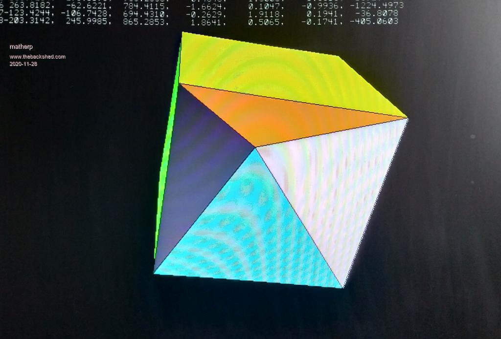 Edited 2020-11-28 21:32 by matherp |
||||
| The Back Shed's forum code is written, and hosted, in Australia. | © JAQ Software 2025 |
