
|
|
Forum Index : Microcontroller and PC projects : CMM2 - 3D extensions, first thoughts
| Author | Message | ||||
| matherp Guru Joined: 11/12/2012 Location: United KingdomPosts: 11499 |
Looking for ideas and input so I thought I'd expose my current thinking - nothing coded so far New command DRAW3D DRAW3D CREATE [#]num, nvertices, vertexarray(), FaceCount, VerticesPerfaceCountArray(), VerticesByFaceArray(), EdgeColoursByFace(), FillColoursByFace() This command creates memory structures holding the input data for the 3D object 'num'. In addition it calculates and stores: Vector normals for the first two edges in each face Coordinates of centroids for each face (simple calculation by averaging the vertices). Faces can have any number of sides but must be convex and the vertices must be listed in a clockwise order looking at the face. If we consider the recent example of the octahedron the data would be as follows: OPTION DEFAULT INTEGER OPTION BASE 1 'For visual simplicity - I never use this DIM nvertices=6 DIM vertexarray(3,nvertices)=(0,250,0, 250,0,0, -250,0,0, 0,-250,0, 0,0,250, 0,0,-250) DIM FaceCount=8 DIM EdgeColoursByFace(FaceCount)=(rgb(red), rgb(green), rgb(white), RGB(blue), rgb(magenta), rgb(yellow), RGB(brown), rgb(gray)) DIM FillColoursByFace(FaceCount)=(rgb(red), rgb(green), rgb(white), RGB(blue), rgb(magenta), rgb(yellow), RGB(brown), rgb(gray)) DIM VerticesPerfaceCountArray(FaceCount)=(3,3,3,3,3,3,3,3) DIM VerticesByFaceArray(MATH(SUM VerticesPerfaceCountArray())=(1,6,3, 1,2,6, 1,3,5, 1,5,2, 4,3,6, 4,6,2, 4,2,5, 4,5,3) NB: these arrays can be erased or re-used after the object is created DRAW3D VIEW viewer(), viewplane This command defines where the viewer is located in 3D space and where the viewplane is located. Again looking at the octahedron example this would be: DIM viewer(3)=(MM.HRES\2, MM.VRES\2,0) DIM viewplane=800 DRAW3D SHOW [#]num, x, y, z, xrot, yrot, zrot DRAW3D WRITE [#]num, x, y, z, xrot, yrot, zrot DRAW3D SHOW [#]num, x, y, z, q() DRAW3D WRITE [#]num, x, y, z, q() These commands project the 3D object onto the viewplane with its centre at x, y, z and rotated about its centre by the angles xrot, yrot, zrot or by the quaternion matrix q() In the case of WRITE the object just overwrites the video page with the projection. In the case of SHOW the firmware will restore the area of the video page that was previously overwritten (if applicable), store the new area of the video page that will be overwritten and then output the projection of the 3D object DRAW3D HIDE [#]num DRAW3D HIDE ALL This command restores the video page with information that was overwritten by a previous SHOW command for the object specified or for all objects. NB: objects that have been written (DRAW3D WRITE) can not be removed by the firmware. DRAW3D CLOSE [#]num DRAW3D CLOSE ALL This command deletes the object specified or all objects and frees up the memory used. If the object(s) are currently showing then they are removed first. NB: objects that have been written (DRAW3D WRITE) can not be removed by the firmware. The code will use the best of the algorithms developed by PeteCotton, vegipete and LeoNicolas for hidden face removal with the addition that it will also incorporate a sort of the face centroids and write the faces in reverse depth order. This should ensure that 3D objects with concave elements can be displayed correctly. Wireframe objects are a special case and are actually harder than solid objects. In order to deal with these correctly they will be treated as solid objects with a face colour of black in order to correctly implement the hidden line removal. They will then be copied to the video page with black treated as transparent. Changing the viewer or viewplane position when objects are SHOWn will require all objects to be hidden and then re-projected from the new perspective. There will be a finite number of 3D objects supported - probably 64 to match sprites and indeed a 3D object is effectively a "super" sprite except that things like collision detection will be left to the MMBasic coder. OK so what have I missed? Edited 2020-11-22 04:23 by matherp |
||||
| PeteCotton Guru Joined: 13/08/2020 Location: CanadaPosts: 630 |
Fantastic work  These are just ideas. The ability to switch perspective off for the camera, so that it's Orthographic. This has been used to good efect in Unity to produce 2D platformers with 3D elements. So, it looks like a platformer, but elements like walls etc. might be destructable 3d objects which explode into particles etc. I'm still working on an algorithm to map any multisided 2D shape on to any other (same # sides) 2D shape. Would there be an possibility of that being a future option (to texture map some or all of the faces of an object? I realise it's asking a lot of both the computer and you)  Is there an option to clip the viewport? This might help significantly reduce draw time (i.e. in Elite the top 2/3rds of the screen is the 3dD view and the bottom 3rd is the control panel). You're going to hate me for this one.... but it is just a suggestion, what about multiple cameras (I know that's a huge ask). But games often use a second view portal for rear view camera's or for the camera on the front of a missile etc (Picture in picture), or even for reflections such as mirrors.3D lines. So for example: If I have a 3D view of stars that my space ship can jump to, and I wanted to draw lines between them (see image below) as the galactic map rotated. 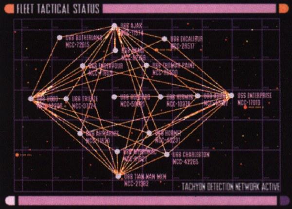 These lines would also be useful to represent things like shield strength around vessels (see below) 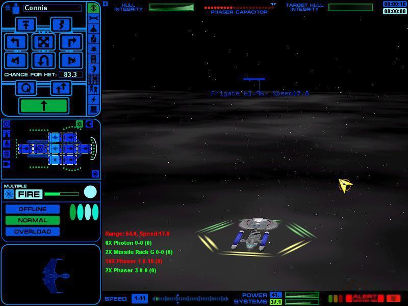 And on a similar note, 3D pixels (for particle effects such as explosions). One that "might" be useful is 3D positioned text. Not the actual text rotated or anything, but just have it obey the draw depth sequence (so that it appears behind objects in front). So say you wanted to attach a name to a starship in the distance (like in the image above), then having the ability to draw text at that X-Y-Z position in 3D space and have that point move with the viewport. The other thing that is applicable, but that we might not have the memory for is the sky map. So in doom etc, there is a spherical map (or hemispherical to be more accurate) of the sky (sun, clouds etc.) that is projected at infinity and drawn first. Effectively this is a 3D background to the image. Note: I'm excited for the stuff you have already outlined, but I thought I would just throw out some ideas. I realise a lot of these are a huge amount of work. Thank you again for everything you are doing for us all!  |
||||
| LeoNicolas Guru Joined: 07/10/2020 Location: CanadaPosts: 582 |
Wow Peter, I'm really impressed with this new CMM2 capability :D How are you dealing with 3D objects clipping for objects going outside of the screen? I have implemented the Sutherland�Hodgman algorithm in my 3D API and it will be great if it can be implemented directly on the firmware. function ClipPolygons(numvert as integer,vx(),vy(),vxout(),vyout(),n()) as integer local integer ic,c,v,totn=0,tvin,tvout,offset=0 local vclip1(2),vclip2(2),vcurr(2),vnext(2),vint(2) local vxin(bound(vxout())),vyin(bound(vyout())) math set -1,vxout() math set -1,vyout() math set 3,n() ' steps trought the polygons for ic=1 to bound(vx()) step numvert for v=1 to numvert c=ic+v-1 vxout(v+offset)=vx(c):vyout(v+offset)=vy(c) next v tvout=numvert ' steps trought the clipping edges for c=1 to 4 if c=1 then vclip1(1)=INT_MIN:vclip1(2)=VIEW_PORT(2) vclip2(1)=INT_MAX:vclip2(2)=VIEW_PORT(2) elseif c=2 then vclip1(1)=VIEW_PORT(3):vclip1(2)=INT_MIN vclip2(1)=VIEW_PORT(3):vclip2(2)=INT_MAX elseif c=3 then vclip1(1)=INT_MIN:vclip1(2)=VIEW_PORT(4) vclip2(1)=INT_MAX:vclip2(2)=VIEW_PORT(4) else vclip1(1)=VIEW_PORT(1):vclip1(2)=INT_MIN vclip2(1)=VIEW_PORT(1):vclip2(2)=INT_MAX end if ' Initializes vxin and vyin math scale vxout(),1,vxin() math scale vyout(),1,vyin() ' Initializes total vertices counter tvin=tvout:tvout=0 ' steps trought the vertices for v=1+offset to tvin+offset vcurr(1)=vxin(v):vcurr(2)=vyin(v) if v=tvin+offset then vnext(1)=vxin(offset+1):vnext(2)=vyin(offset+1) else vnext(1)=vxin(v+1):vnext(2)=vyin(v+1) end if if IsInside(vcurr(),vclip1(),vclip2()) then if IsInside(vnext(),vclip1(),vclip2()) then tvout=tvout+1 vxout(tvout+offset)=vnext(1):vyout(tvout+offset)=vnext(2) else CalcIntersection(vcurr(),vnext(),vclip1(),vclip2(),vint()) tvout=tvout+1 vxout(tvout+offset)=vint(1):vyout(tvout+offset)=vint(2) end if elseif IsInside(vnext(),vclip1(),vclip2()) then CalcIntersection(vcurr(),vnext(),vclip1(),vclip2(),vint()) tvout=tvout+1 vxout(tvout+offset)=vint(1):vyout(tvout+offset)=vint(2) tvout=tvout+1 vxout(tvout+offset)=vnext(1):vyout(tvout+offset)=vnext(2) end if next v next c if tvout > 2 then offset=offset+tvout totn=totn+1 n(totn)=tvout end if next ic ClipPolygons=totn end function function prt(v) as string prt=str$(v,0,0) if v=INT_MIN then prt="-I" elseif v=INT_MAX then prt=" I" end if end function sub CalcIntersection(v1(),v2(),c1(),c2(),vout()) local s1(2)=(v2(1)-v1(1),v2(2)-v1(2)) local s2(2)=(c2(1)-c1(1),c2(2)-c1(2)) local d=-s2(1)*s1(2)+s1(1)*s2(2) local s=(-s1(2)*(v1(1)-c1(1))+s1(1)*(v1(2)-c1(2)))/d local t=( s2(1)*(v1(2)-c1(2))-s2(2)*(v1(1)-c1(1)))/d if s>=0 and s<=1 and t>=0 and t<=1 then vout(1)=t*s1(1)+v1(1) vout(2)=t*s1(2)+v1(2) end if end sub function IsInside(v(),c1(),c2()) as integer IsInside=0 if c1(1)=c2(1) then ' Same X if c1(1)=VIEW_PORT(1) then IsInside=v(1)>=c1(1) else IsInside=v(1)<=c1(1) elseif c1(2)=c2(2) then ' Same Y if c1(2)=VIEW_PORT(2) then IsInside=v(2)>=c1(2) else IsInside=v(2)<=c1(2) end if end function |
||||
| LeoNicolas Guru Joined: 07/10/2020 Location: CanadaPosts: 582 |
@PeteCotton, the screenshots that you shared are amazing  I can wait for playing your game  |
||||
| PeteCotton Guru Joined: 13/08/2020 Location: CanadaPosts: 630 |
Ha ha - I wish. They were from the game my new game is originally modelled on (Star Trek - Star Fleet Command). Still one of my all time favourite games. I originally started working on a text based 1980's Star Trek, then started playing with the 3D stuff and realised that I could do a passable 3D engine in BASIC for the game. But this new 3D firmware functionality would allow me to take it to a whole new level. Of course, it won't be "Star Trek" as I respect the franchise/IP, but the game play will be along these lines..... if I ever get it completed. |
||||
| matherp Guru Joined: 11/12/2012 Location: United KingdomPosts: 11499 |
The graphics primitives simply don't draw pixels that are outside of the screen In the latest release there is the ability to define specific page as having a smaller size than the native size for the video mode. This will allow you to use such a reduced page for drawing the 3D objects and then BLIT the smaller page onto the display page in the position required. It could be possible to define a camera position and viewplane per page so that the same 3D object could be projected onto different pages (of different sizes) from different perspectives but that one will need the grey cells to be firing on all cylinders and is definitely phase 2. Definitely yes, why not restrict to just 3 and 4 sided as these should make up nearly all 3D objects |
||||
| LeoNicolas Guru Joined: 07/10/2020 Location: CanadaPosts: 582 |
Gratulations Peter... this is awesome... How are you thinking to implement 3D object scaling? |
||||
| PeteCotton Guru Joined: 13/08/2020 Location: CanadaPosts: 630 |
I have the 3 sided one working fine and I am very happy with it. When I started doing the four sided algorithm I realised that there were a tonne of similarities between the two algorithms, so, stupidly thinking that I was a lot smarter than I really am, I thought I could produce a common algorithm to do all number of sides. It turned out to be quite tricky. So, yes, I will keep trying but it may be that the best answer is just to do custom code for 4 sided and 3 sided and leave it at that. Do you mean Level Of Detail? Because I'm probably going to use sprites for the distant objects (each ship rotated through 8 different directions), and then as they get in closer convert to a 3D-Object. |
||||
| vegipete Guru Joined: 29/01/2013 Location: CanadaPosts: 1179 |
I need to process this more... My initial observation is that the viewer position is insufficiently specified. In addition to x,y,z, you need roll/pitch/yaw to fully constrain the viewer. The octahedron challenge assumed the viewer was looking at the origin and was 'upright'. Some of my initial experiments moved the viewer in polar coordinates around the origin. My conclusion was that roll could be accomplished in two dimensions after the object had been projected onto the viewing plane, given that the viewing plane is perpendicular to the line of sight. It would also be nice to be able to apply a 4x4 transformation matrix to each vertex stored in vertexarray(3,nvertices) I was reading about the characteristics and algorithms in BattleZone. Something it did was change the intensity of lines based on the distance away an object was. I'm not sure how that could be mimicked, although you are part way there with centroids and depth order. Your wireframe ideas are unclear. If hidden lines are removed from a wireframe object, why would you then copy them with transparent faces? Perhaps there could be two modes: face colour = black behaves exactly like face colour = anything else and wireframe mode where faces are ignored completely, so everything shows. Just project all the (rotated etc) vertices and draw all the faces with no fill - don't worry about the direction of the face normal. Fun! Visit Vegipete's *Mite Library for cool programs. |
||||
| LeoNicolas Guru Joined: 07/10/2020 Location: CanadaPosts: 582 |
The level of details x distance is another problem, and I think we will not have to worry about it, our models will use a small number of polygons. I'm asking about objects scaling... something line increasing or reducing the size of the vertices by a factor (2x, 3x, etc) It's about the third main object transformation... translate, rotate and scale Edited 2020-11-22 11:04 by LeoNicolas |
||||
| matherp Guru Joined: 11/12/2012 Location: United KingdomPosts: 11499 |
Here is an example of using the page resize to clip the 3D projection based on the ELITE demo from Pete. Check the FPS - suggest you update to V5.06.00b3 has it has a slight performance update mode 1 scale=1 xpos=00 ypos=200 scaleup=0 dim vertex(11,3) ' Store 11 vertex points of x, y and z co-ordinates dim nodeCount%=11 dim plane(16,4) ' Planes are made up of 3 or 4 vertexes dim drawNodeX(16) ' Stores the translated X,Y,Z co-ords of each node/vertex dim drawNodeY(16) dim drawNodeZ(16) dim colours(16) dim blacks(16) dim polyX(17*3+5) ' The array we use to store the points of the polygons dim polyY(17*3+5) dim PolyC(16) ' Vertex data is stored in 2 dimensional array where the 2nd dimension defines x, y or z vertex(0,0)=32:vertex(0,1)=0:vertex(0,2)=76 vertex(1,0)=-32:vertex(1,1)=0:vertex(1,2)=76 vertex(2,0)=0:vertex(2,1)=26:vertex(2,2)=24 vertex(3,0)=-120:vertex(3,1)=-3:vertex(3,2)=-8 vertex(4,0)=120:vertex(4,1)=-3:vertex(4,2)=-8 vertex(5,0)=-88:vertex(5,1)=16:vertex(5,2)=-40 vertex(6,0)=88:vertex(6,1)=16:vertex(6,2)=-40 vertex(7,0)=128:vertex(7,1)=-8:vertex(7,2)=-40 vertex(8,0)=-128:vertex(8,1)=-8:vertex(8,2)=-40 vertex(9,0)=0:vertex(9,1)=26:vertex(9,2)=-40 vertex(10,0)=-32:vertex(10,1)=-24:vertex(10,2)=-40 vertex(11,0)=32:vertex(11,1)=-24:vertex(11,2)=-40 plane(0,0)=2:plane(0,1)=1:plane(0,2)=0 plane(1,0)=0:plane(1,1)=1:plane(1,2)=10:plane(1,3)=11 plane(2,0)=6:plane(2,1)=2:plane(2,2)=0 plane(3,0)=0:plane(3,1)=4:plane(3,2)=6 plane(4,0)=7:plane(4,1)=4:plane(4,2)=0:plane(4,3)=11 plane(5,0)=1:plane(5,1)=2:plane(5,2)=5 plane(6,0)=5:plane(6,1)=3:plane(6,2)=1 plane(7,0)=1:plane(7,1)=3:plane(7,2)=8:plane(7,3)=10 plane(8,0)=9:plane(8,1)=5:plane(8,2)=2 plane(9,0)=2:plane(9,1)=6:plane(9,2)=9 plane(10,0)=3:plane(10,1)=5:plane(10,2)=8 plane(11,0)=7:plane(11,1)=6:plane(11,2)=4 plane(12,0)=10:plane(12,1)=8:plane(12,2)=5 plane(13,0)=11:plane(13,1)=7:plane(13,2)=4 plane(14,0)=9:plane(14,1)=10:plane(14,2)=8:plane(14,3)=5 plane(15,0)=9:plane(15,1)=6:plane(15,2)=7:plane(15,3)=11 plane(16,0)=9:plane(16,1)=11:plane(16,2)=10 sub rotate(ax, ay, az) snz=sin(az) csz=cos(az) sny=sin(ay) csy=cos(ay) snx=sin(ax) csx=cos(ax) for n=0 to nodeCount% x=vertex(n,0) 'x y=vertex(n,1) 'y ' Rotate around z drawNodeX(n)=x*csz-y*snz drawNodeY(n)=y*csz+x*snz drawNodeZ(n)=vertex(n,2) 'z ' Rotate around y x=drawNodeX(n) z=drawNodeZ(n) drawNodeX(n)=x*csy+z*sny drawNodeZ(n)=z*csy-x*sny ' Rotate around x y=drawNodeY(n) z=drawNodeZ(n) drawNodeY(n)=y*csx-z*snx drawNodeZ(n)=z*csx+y*snx next n end sub anglex=0:angley=0:anglez=0 page resize 1,400,300 page write 1 cls 'Main loop lc=0 do tts=timer cls anglex=anglex-0.00005 angley=angley+0.01 anglez=anglez+0.025 rotate(anglex,angley,anglez) tt2=timer PolyPos=0 PolyCount=0 for v=0 to 16 p1=plane(v,0) p2=plane(v,1) p3=plane(v,2) p4=plane(v,3) x1=drawNodeX(p1) y1=drawNodeY(p1) ' z1=drawNodeZ(p1) x2=drawNodeX(p2) y2=drawNodeY(p2) ' z2=drawNodeZ(p2) x3=drawNodeX(p3) y3=drawNodeY(p3) ' z3=drawNodeZ(p3) dx1=x1-x2 dy1=y1-y2 dx2=x1-x3 dy2=y1-y3 ' crossX=y1*z2-z1*y2 ' crossY=z1*x2-x1*z2 crossZ=dx1*dy2-dy1*dx2 ' norm=sqr(crossx*crossx+crossy*crossy+crossz*crossz) ' lightLevel=128+ (127*(crossY/norm)) 'dotproduct=x1*x2+y1*y2+drawNodeZ(p1)*drawNodez(p2) if crossZ>0 then polyx(PolyPos)=x1 polyy(PolyPos)=y1 polyx(PolyPos+1)=x2 polyy(PolyPos+1)=y2 polyx(PolyPos+2)=x3 polyy(PolyPos+2)=y3 PolyPos=PolyPos+3 colours(PolyCount)=rgb(128+v*5,255,255) if p4=0 then PolyC(PolyCount)=3 else 'It's a 4 point plane PolyC(PolyCount)=4 polyx(PolyPos)=drawNodeX(p4) polyy(PolyPos)=drawNodeY(p4) PolyPos=PolyPos+1 endif PolyCount=PolyCount+1 endif next v polyc(polycount)=0 'mark the end of valid polygons math scale polyx(),scale,polyx() math scale polyy(),scale,polyy() math add polyx(),xpos,polyx() math add polyy(),ypos,polyy() polygon PolyC(),polyx(),polyy(),blacks(),colours() if scaleup then xpos=xpos-1 ypos=ypos+0.5 scale =scale +0.002 if xpos=0 then scaleup=0 else xpos=xpos+1 ypos=ypos-0.5 scale =scale -0.002 if xpos=400 then scaleup=1 endif timerTotal=timer-tts timerRotate=tt2-tts timerDraw=timer-tt2 fps=fps*0.9+0.1*(1000/timerTotal) print @(0,0)"FPS: " +str$(fps) ' print "Rotate: " + str$(timerRotate) +" ms" ' print "Draw: " + str$(timerDraw) + " ms" ,lc lc=lc+1 page write 0 blit 0,0,200,150,400,300,1 page write 1 ' page copy 1,0 loop |
||||
| PeteCotton Guru Joined: 13/08/2020 Location: CanadaPosts: 630 |
Wow. My imagination is running wild with what we could do with this. |
||||
| LeoNicolas Guru Joined: 07/10/2020 Location: CanadaPosts: 582 |
Amazing Peter. My only concern is when I was using triangle or polygon commands to render 3D objects my program was crashing when the vertices coordinate was reaching some values outside the screen (negative or positive huge values). I believe for the new 3D command you are checking these coordinate values before rendering them. |
||||
| The Back Shed's forum code is written, and hosted, in Australia. | © JAQ Software 2026 |
