
|
|
Forum Index : Windmills : 7.5HP Three Phase Motor Conversion
| Author | Message | ||||
| GWatPE Senior Member Joined: 01/09/2006 Location: AustraliaPosts: 2127 |
Hi Sparweb & herbnz, the synchronous machines I have seen previously had wound rotors and slip rings. I doubt that the natural characteristics of a squirrel cage will provide the gain in rotor magnetic field to change the output from a square relationship to a cubic output relationship. The positive controlling of increasing of the field with rpm with the addition of a wound rotor to the permanent magnets is what I was suggesting. I would however be reluctant to add any component to the rotor that added a heating component. Neo magnets have low curie temperatures. The first set I tested, went rusty very quickly. [prior to nickel coatings]. I painted them and dried in the sun. They lost all magnetism. The capacitors have not shown a significant change in the output current/voltage relationship on the F&P I tested on. The fact that rotor bars are added to reduce hunting, would imply that power is required in this process. Gordon. become more energy aware |
||||
oztules Guru Joined: 26/07/2007 Location: AustraliaPosts: 1686 |
For a 4 pole device, I suspect series caps will be in the thousands of UF. Maybe try caps in parallel, because..... if I recall correctly Zubbly had 1500uf in series on a 12 pole 7.5hp conversion... and that was into a resistive load which.... would put you lots higher still. If your airgap is a little sloppy it may also prevent the armature reaction from being as useful as Herb hopes, as the back MMF has to contend with the larger gap, just as the neo's do.. It may still help by giving it a leading PF to help straighten out the MMF:back MMF tussel... (or lower the inductive reactance, but at these frequencies, I suspect it is Herbs MMF theory that holds up best) ..........oztules Village idiot...or... just another hack out of his depth |
||||
herbnz Senior Member Joined: 18/02/2007 Location: New ZealandPosts: 258 |
Oztules No need for large caps Many standard induction motors have been excited with less than 100 mfds. Not usually a success cause of load speed dependancy but they do excite. Not attempt to straightern lines just add compensation as a series generator does on DC . Commonly refered to as the series effect. Gordon Hunting is not envisaged here or never was . I take it from your comments re caps on FP that your work on Capacitors is now at a end . If a successful conclusion was not reached your work was not in vain as it has inspired at least myself to look at the effects of caps in series in the future. ps Note the rotor bars will only have induced currents if the stator current manages to produce flux this can only come about by hunting (not envisaged here ) or phase shifts in load pf. Herb |
||||
SparWeb Senior Member Joined: 17/04/2008 Location: CanadaPosts: 196 |
I can't picture buying capacitors to use with this generator. The Voc is >200V at even modest RPM's. Obtaining a high-value capacitor with a high voltage tolerance is an expensive proposition, even if I compromise and buy polarized ones and set them up back-to-back. 
Back when I was trying to follow Gordon on the series capacitors issue, I tried a few experiments of my own, with different capacitance values, on my existing mill. I found no combination of series or parallel, at 1500/2300/4500 uF, that had any positive effect. I only found that both 1500+4500 uF caused decreases in current, and series 2300 uF was like it wasn't even there. No change in speed at any time. I abandoned the experiment, and when I saw Gordon's diagram of many more capacitors than I had imagined, feeding through the top 12V and the bottom 12V of the battery bank, I realized that this F&P requires special treatment of a totally different nature than the industrial motor conversion. I plotted the test data on a curve with a simple "Ohm's Law" model. The output figures cut-in at the same point, and eventually fall off as speed/current rise, whereas the prediction is for a linear increase. About 50% less current is generated at 600 RPM. That corresponds to about 25 Amps versus a predicted 50 Amps, occurring at 4 times the cut-in speed, when the open-circuit voltage has become greater than 200V. Later I will quantify this drop-off and propose a model of how much back-MMF is present, de-magnetizing the neos. If we can suggest a size and design of bars that will *on their own* counteract that, then I'm all ears. 
Herb, go analytical on me. Please. I'm lead-balloon free. Steven T. Fahey |
||||
| oztules Guru Joined: 26/07/2007 Location: AustraliaPosts: 1686 |
Herb, The large cap size was not to initiate excitation.... just to get the power out if in series. The XC of 100uf@5-15hz (4 pole unit) will be very high. If it did excite,and if it did get extra MMF because of ... well any reason, you won't see it at the output because of the high cap reactance. I have excited induction motors with less than 50uf in parallel, so no problems there (1400rpm.. 50hz), but the series bit bothers me. Gordon had 10 times the poles to play with so series was practical from a XC standpoint, 4 pole at 3-400rpm isn't. eg. XC @15hz for 100uf is about 100 ohms. He would have trouble getting 20A through that I suspect 
I can only see it practically working as direct connect with caps in parallel. Even 2000uf would be about 5ohms XC. At 20 amps, thats 100v drop across the caps in series. I think I understand what you are trying to expound, but the series caps bother me at these frequencies. 
Be a neat idea to try though. ..........oztules Village idiot...or... just another hack out of his depth |
||||
| GWatPE Senior Member Joined: 01/09/2006 Location: AustraliaPosts: 2127 |
I don't know what you mean by successful conclusion was not reached. I do not have a mathematical explanation that can be used to calculate appropriate caps for any installation, so no. Phill has a working dual F&P windmill with star/delta and capacitor doublers that performs better. He may wish to elaborate himself. My system works with cap doubler and AC coupling to 24V&48V loading. These systems extract wind energy close to the optimum, across a wide range of wind energy at the low to mid power output levels. The upper power levels is subjective and many factors including furling, impact on results. I will not add more, as this is not related to the jist of this thread. Followup may be better in cap testing or the main cap thread. Gordon. become more energy aware |
||||
| herbnz Senior Member Joined: 18/02/2007 Location: New ZealandPosts: 258 |
Sorry Gordon I was reading this in your previous posting Herb Oztules You are right again. But it would be still a step on to test in parallel and then in series .to see effects and while doing that just see in case of slimist chance there is some effect. There is some highly distored waveforms around that have high frequency harmonics that may create some effect good or bad. Every well documented test good or bad is a step to our knowledge . Herb |
||||
| GWatPE Senior Member Joined: 01/09/2006 Location: AustraliaPosts: 2127 |
Sorry Sparweb, as this is not related to your thread. Hi herb, You were reading something else into what I posted. This comment was in relation to the voltage and current phase relationships, and has nothing to do with the loading characteristics of the windmill, by the alternator that is achieved with capacitors. In relation to my other comments in many other topics, do you really think I would conclude that capacitors basically made no difference to loading. A relationship between current and voltage is purely that. This cannot be concluded to relate to a loading relationship as well. Sorry again Sparweb. Gordon. become more energy aware |
||||
| Dinges Senior Member Joined: 04/01/2008 Location: AlbaniaPosts: 510 |
[quote=Steven]I don't worry much about the thrust load... Have you ever worked out the gyroscopic loads? I want the big bearing on the front for that![/quote] I haven't worked out the yaw forces but they're likely substantial. However, those forces will load both bearings in a radial direction for which those deep-groove ball bearings are specifically intended. Did a quick check for the 6208 bearing (the smaller of the two bearings on the 10hp) and it has a dynamic rated load (C) of 32.5kN. I expect to see the tower fall over before the bearing fails... 
However, the axial thrust load is a much more pernicious load for deep-groove ball bearings. To my surprize (I did the math for the 10hp conversion) the large bearing should be able to stand this load, staying well within its rating. The (simplified) lifetime calculations yielded a L10h of around 15 years (from memory). Most likely corrosion will shorten this lifetime to much less, but it's good to know that the axial loading will be accepted without too much trouble and not be a practical limit on bearing life. As for the gyroscopig yawing forces... I'm still toying with the idea of active yawing. I don't find the elliptical furling system (the common method on axial flux alternators) a satisfying solution at all. Long tail, rapid yawing, and plain ugly to look at. Not an elegant solution (though it is a pretty clever design). Not sure though that I can come up with a better, more reliable solution for yawing using a motor, windvane and some controlling electronics. [quote=Steven]As for the air hose, that wasn't my idea. If it was my Colchester, I'd be cleaning it with a toothbrush. Actually, years ago, it was my job to clean it from time to time. Time, new shop personnel, and changing responsibilities at the company carry me away from those "good old days".[/quote] In the metalworking shops that I'm familiar with, you'd literally get kicked out of the shop just for even *considering* using compressed air for cleaning machines. And rightly so, in my opinion. It's a great way to ruin machines. 
Peter. |
||||
| Janne Senior Member Joined: 20/06/2008 Location: FinlandPosts: 121 |
Have you considered the fan tail? If at first you don't succeed, try again. My projects |
||||
| SparWeb Senior Member Joined: 17/04/2008 Location: CanadaPosts: 196 |
First off, I must say that I like your new picture. So many people choose smaller noses in cosmetic surgery... 
Active yawing is a great way to go if you're ready to tackle the complexity. For a big enough windmill, it's probably worth considering. Someone comfortable with the necessary parts (servo, controller, power supply & sensors) should be able to do it, though I just don't see many examples on these fora. My estimate of thrust on my 8' mill is only 30 pounds (120 N), beyond which furling begins. I know, even that much thrust will have an effect on the life. But if you did go to the trouble of finding the gyroscopic forces... Life is also a factor of cost, so I have FAG's in the GE generator right now. Looks like I will be shelling out extra bucks for the Toshi, too, because depending on which mfr's books I look at, the bearing load ratings are borderline. Don't get me wrong - I have reason to be worried about these things. My GE conversion is making "noises" and they aren't just wind noises. If there wasn't 1/2 meter of snow and ice around the tower, I'd rather take it down and change out the bearings. Perhaps some post-mortem photos would be welcome when I take it apart in the spring. Steven T. Fahey |
||||
| SparWeb Senior Member Joined: 17/04/2008 Location: CanadaPosts: 196 |
OOh this was fun! I just discovered that there is an on-line calculator on the FAG website.  I put the stats for my machine's service (some numbers off the top of my head). I could fix it up with better numbers once I've sized the prop, settled on the furling speed, etc. I put the stats for my machine's service (some numbers off the top of my head). I could fix it up with better numbers once I've sized the prop, settled on the furling speed, etc.
2009-02-06_072909_6308_FAG_Calc_Report.pdf 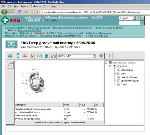
Steven T. Fahey |
||||
| Dinges Senior Member Joined: 04/01/2008 Location: AlbaniaPosts: 510 |
[quote=Steven]Life is also a factor of cost, so I have FAG's in the GE generator right now.[/quote] So... you're saying that cheap Chinese bearings are not up to the task, even though they have the right numbers printed on them? (feigns shock) Yes. And that's the reason I use nothing but SKF. But I wouldn't hesitate to use FAG too. Or NSK. But anything else is a definite no-no. [quote]My GE conversion is making "noises" and they aren't just wind noises.[/quote] Hm. But I'm curious: did you install new bearings in that conversion (and if so, what brand), or did you re-use the old ones? And if they were new: how long did they last? I love those online calculators too (I'm only familiar with the SKF one; or the manual method...  ), but they don't tell everything. They don't take environmental factors much into account. And that's one particularly important point in a windturbine. BTW, I think I would have chosen 'influence of ambient' in those calculations not as 'standard', but something a little more conservative ('harsh' or 'severe'). Especially if I were living in Canada... ), but they don't tell everything. They don't take environmental factors much into account. And that's one particularly important point in a windturbine. BTW, I think I would have chosen 'influence of ambient' in those calculations not as 'standard', but something a little more conservative ('harsh' or 'severe'). Especially if I were living in Canada...
I notice your 7.5hp uses the same bearing(s?) (6308) as my 10hp (which uses both a 6208 and a 6308, but only because it's the rugged variant of this range of motors; the standard bearing configuration is 2pcs. 6208, both in the driven and non-driven end...). So in that respect your conversion will be more rugged than mine. Peter. (PS: using online calculators is cheating...  ) ) |
||||
| SparWeb Senior Member Joined: 17/04/2008 Location: CanadaPosts: 196 |
[quote=Dinges]...using online calculators is cheating...[/quote] In my defense, I have under my belt several work projects (before the time on on-line calculators) to validate the use of new bearings in some extremely punishing environments. Ever been tasked with selecting new bearing for an oil cooler blower fan mounted in a transport helicopter? The lesson from that one was that you don't start such projects when the customer expects the replacement bearing to be CHEAPER than the OEM bearing, yet last longer! As for my own environment, I didn't spend enough time with the calculator yet to try different temperature ranges. Indeed, the noise I report only happens below -25 Celsius, so I shouldn't have been using spring/fall temperatures in the calculator. The GE motor got a fresh set of FAG bearings, so rest assured. I don't remember the sizes off the top of my head. The Toshi is still using its old bearings, but changing them is on the to-do list. The Toshi's bearings are 6308-front and 6208-back. I will pick up some SKF or FAG when the time comes. As a rough guide, I found that a Yaw moment of 6000 inch-pounds is a good number, to take into account very rapid yawing of an 8-foot prop turning at some >1000 RPM. That was one of the parameters I used for the GE and its tower. I would scale up this number by the diameter squared, for whatever prop I put on Toshi. Probably a 12' diameter, hence 2.25*6000=13,500inch-pounds. (1372 Nm?) On other fronts... I am becomeing a bit concerned about the torque required to turn the shaft, now. A few calculations of wind power compared to shaft power, even at low speed, leading to a fairly high cut-in speed.... May only be a problem in Delta, it certainly turns more freely in Star. ...another reason to try "Jerry"...? Still working on it (only have a little free time per day). By the way, the input power curve is STRAIGHT! Assuming a cubic anything was wrong. Apart from the hockey-stick bend at 1000 Watt, the upper part is a straight line. This is proving to be very difficult to fit to the wind power curve. Steven T. Fahey |
||||
| oztules Guru Joined: 26/07/2007 Location: AustraliaPosts: 1686 |
I would hope that most of your power will come from the 200-300rpm range, so perhaps the gyro force is not what you think. I know Zubbly ran his at much higher rpm, but I would not wish to live next to it then. Quick yawing is more for little machines, I have yet to see a "fast" yaw on my 4m unit... it's at ground level and is exposed to much less tidy air than what you should see up high. At 24v, I think your stator wire is a bit on the skinny side for a 12' prop.... so 48v Jerry looks the best option. I figure a TSR of 5 will get you started at 10mph (maybe with a 12mph gust to get 1kg/m torque to get her going). I don't see it turning over much before that. This will give you 200-4000w to play with (squander on that resistance) over the 100-300 rpm range. It's no secret that I will be interested to see how it goes in the real world..... not sure I fancy hoisting it up though. That high resistance will give you some flexibility with the TSR.. 
.........oztules Village idiot...or... just another hack out of his depth |
||||
