
|
|
Forum Index : Windmills : NEW better Chinese blades, with our help.
| Page 1 of 3 |
|||||
| Author | Message | ||||
| Gizmo Admin Group Joined: 05/06/2004 Location: AustraliaPosts: 5012 |
Hi Guys I've been in contact with Wes LeMarr, who some of you may remember posted a message a few days ago looking for advise on a windmill design he hopes to bring to market. Wes has factories in Germany, China and the USA. Wes called me from the USA last night and we had a chat about blade options for his windmill. I told Wes the standard fibreglass blades supplied with those cheap Chinese windmills let the rest of the machine down, and he should strive to come up with a better blade design to include with his windmill, and of interrest to us, sell seperately to the home built windmill market. The blades would be manufactured at the factory in China, where they have access to a PVC extrusion machine and router. Making a new die for the PVC extrusion is not a problem. What does this mean? It means we have the opportunity here and now to design a new blade profile for mass production. The blades will be PVC, and any length from under 1 meter to over 2 meters ( a 4 meter turbine or bigger ). Because they are extrusion made blades, there is no twist or taper, just like those fibreglass chinese blades, however Wes's factory has access to cnc router equipment that can cut the blades to the correct taper. By putting our heads together we should be able to come up with a extrusion shape that can be routered to give the best taper and twist/angle. Hopefully the picture below will explain what I'm trying to say. The top profile is the end view of the extrusion. Bottom left is the blade with 3 stations shown, top side facing the wind, and a concave router tip. The router concave is the same radius as the leading edge of our blade. By routing a line down the length of the blade, as shown in the middle bottom image, we end up with a finished blade, shown bottom right. This is a very cheap way of mass producing blades, and this will reflect in their price. What do you think? Is there another way we can use an extruded length of PVC of any shape we desire to produce a good blade? What do we get out of helping Wes? We get a better option that the straight fibreglass blades currently on the market, in more sizes, and possibly for less cost. It also means Wes can get his windmill to market with a better set of blades, and thats got to be a good thing. Glenn 
The best time to plant a tree was twenty years ago, the second best time is right now. JAQ |
||||
philb Regular Member Joined: 05/07/2008 Location: United StatesPosts: 96 |
Hi Glen, You are probably going to get a lot of people with favorites. So here's mine...Gottingen series 222 through 234. IMHO, they seem to lend themselves well to longer lengths.  http://www.ae.uiuc.edu/m-selig/ads/coord_database.html http://www.ae.uiuc.edu/m-selig/ads/coord_database.html
My last set of blades closely resemble the 227's dimensions. They are quiet and very strong with no twist and no taper. I would suggest making them in say, 2 and 4 meter blades so the end user could cut and trim them to fit their own application. They also need to be fairly cheap in price. 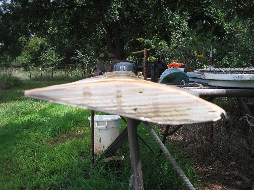 philb |
||||
Gill Senior Member Joined: 11/11/2006 Location: AustraliaPosts: 669 |
Glenn, I think your approach is about all that can be done considering the material used. I see that it is the profiles thickness that allows some twist to be gained from the tapering, therefor a profile with good root thickness is needed. For home modifications there is no need to stick with the same profile for the full blade length. Philb's 'Gottingen series 222 through 234' looks like a low speed, high lift profile with a goodly thickness that is fine for the root, with say the more high speed Clark Y profile for the tip. Perhaps this much modification of the base extrusion is not economical for production. But certainly something with a larger chord to say 200mm is needed. Also unlike your site suggestion of tapering from root to tip, it can be improved by tapering only from the point where the extrusion and the blade profile calculator's shape can be made to match. This may be from around 1/2 way along the blade to the tip. Great link philb. Thanks was working fine... til the smoke got out. Cheers Gill _Cairns, FNQ |
||||
| sPuDd Senior Member Joined: 10/07/2007 Location: AustraliaPosts: 251 |
Glenn, first up I have no idea how extrusion for PVC works. But I'll throw in anyway. Can you setup the die to reduce in size as the blade comes out like a camera aperture? Thus the root comes out first and as the blade passes the die shrinks down to cause taper? If it were possible, I'd try to rotate the die as well to add twist. Probably a wasted post here, but threw in an idea anyway :-) It should work ...in theory |
||||
wdyasq Newbie Joined: 29/07/2008 Location: United StatesPosts: 21 |
"Because they are extrusion made blades, there is no twist or taper, just like those fibreglass chinese blades,...." There is no reason an extrusion can't have a 'twist' The twist would need to be constant and there would be only that one 'twist' available. There was some work done using straight sections and a "tip" and "boot" section. The result was very near the 'optimized' blade. Selecting the proper airfoil may be a challenge. Airfoils are dependent on 'Reynold Numbers' and those depend on cord length and velocity... which become variables as the blades spins and changes speeds. Wind turbines work on principles that are complex. They are a combination of electrical, rotary and fluid dynamics with a bit of mechanical work thrown in to keep it interesting. It is amazing to me how well home-built designs are as developed as they have become considering there is little professional assistance and even less research money. Ron Adventure is just bad planning." -- Roald Amundsen |
||||
| philb Regular Member Joined: 05/07/2008 Location: United StatesPosts: 96 |
Gill, you have a sharp eye. Actually, I made this blade to start up in very low wind. At 750 RPM, with the generator completely unhooked, it gets noisy, but does not want to go any faster. BTW, I would prefer to get the speed down in the 500 RPM range so I can make larger blades. It was specifically designed with the extrusion process in mind. Please don't get me wrong, I'm not trying to sell blades here, just suggesting an idea.
Spud, this URL will bring you up to speed on the basic extrusion process. http://en.wikipedia.org/wiki/Extrusion Look under plastics extrusion. I'm guessing this is what Wes will be using. After the blade comes out of the extruder, it can be at a temperature that will facilitate a twist or series of twists. However, the simpler the design, the lower the cost of the final product will be. A separate extruder can produce the base for generator attachment...or use a hub like in Grolly's post. philb |
||||
| Jarbar Senior Member Joined: 03/02/2008 Location: AustraliaPosts: 224 |
Hello Wes Glenn Trevor and others, Another type of forming process which I used to be involved with is vacume forming.If the plugs for forming were made with the process Glenn and Trevor employed to produce the fiber glass blades described at the earlier links.But instead of laying up fiber glass to make the two halves and then joining them.The same plugs could be used with some modification in a vacume forming machine.In this process the PVC material could be used in sheet form or strip form.It is held in position over the mould while a heat source is used to evenly warm the PVC.Once attaining the desired amount of heat in the PVC it is then clamped down over the mould and a vacum is applied to the cavity of the mould drawing the heated PVC into the shape of the plug.The process is sometimes improved by applying posotive air pressure to the top side of the sheet being formed.This process would be done to form both the front and rear of the blades.Then another step is required to fuse the two halves together either using an ultrasonic welder or a hot metal element in a plug of similar shape to the forming plug.Once set up a rapid production of different sized blades in the same machine can be achieved.Only the plugs for different blade sizes need to be fitted for a given production run.A simple example of this process is the forming of Blister packaging to display goods in local hardware store.Another associate would use it to reform Vinyl for replacement dashboards in cars.This will give a hollow light weight and very stiff blade with excellent repeatability.The set up cost will initially be higher but the end result far quicker than machining blades with a CNC router.With far less mess. 
More food for thought Anthony. "Creativity is detirmined by the way you hold your tounge".My Father "Your generation will have to correct the problems made by mine".My Grandfather. |
||||
MadRat Newbie Joined: 30/09/2008 Location: United StatesPosts: 21 |
If he's going to the trouble of extrusion then why not extrude a true aerofoil shape - there are already plenty of proven shapes out there - and include a hollow cavity where appropriate? He could have two models; simple aerofoils with caps to cover the hollow point at the tip, and the deluxe version complete with winglets that attach (screw/glue?) into the hollow cavities at the end. Go Huskers! |
||||
| Gizmo Admin Group Joined: 05/06/2004 Location: AustraliaPosts: 5012 |
Hi Guys Would there be a profile that would work reasonably well without any twist or taper, like the Chinese blades only better? A profile thats acceptable for a production windmill in the 2 to 4 meter diameter range. The Chinese blades have a problem with noise, but other than that they work OK'ish. Royal Fabrication in the USA (http://www.royalfabrication.com/) make a straight timber blade thats works very well, pic below.... 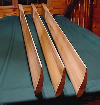
If straight PVC blades become available for the home made windmill market, we could taper them to improve performance. I would rather work PVC than fibreglass any day. I spoke to Wes today and he said vacuum forming was not an option, but a hollow blade was do-able. There would be a weight reduction, but any reshaping would be out of the question. Glenn The best time to plant a tree was twenty years ago, the second best time is right now. JAQ |
||||
| MadRat Newbie Joined: 30/09/2008 Location: United StatesPosts: 21 |
The hollow should in theory improve the strength of the blade if engineered correctly. Less materials. Less costs in shipping by weight. It just makes sense overall to use a hollow design. The mounting holes would need to be done through a solid section of the blade, not in the hollows like the extruded aluminum blades are done. Clamping down the nuts too tight when mounting them distorts or cracks the blades. On something like this he probably wants spacer bushing in the mounting holes to prevent a consumer applying an excess of torque; the excess energy goes into the spacers rather than into the blades. Washers on each side of the spacer keep the blade in place. I mentioned a winglet for the cap because on aircraft it can make a 5% difference in drag just due to the canceling out of wingtip vortexes. You'd want a cap over the end anyhow; a winglet cap would be something both for utility and beauty at the same time. Go Huskers! |
||||
| Wes Lemarr Newbie Joined: 07/09/2008 Location: United StatesPosts: 35 |
MadRat, Your idea of using a "winglet" end cap, what do you envision it looking like? I think this sounds like a very good idea, maybe you could post a sketch of your concept. Thanks & Best Regards Wes LeMarr |
||||
| MadRat Newbie Joined: 30/09/2008 Location: United StatesPosts: 21 |
Here's a quick idea made up in ms paint. 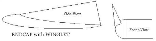
Go Huskers! |
||||
| Ken. Newbie Joined: 05/10/2008 Location: AustraliaPosts: 13 |
Hi guys, As a pilot (helicopters) I suggest a little caution on the wing tips. They are usually mounted on the end of fixed wing aircraft wings, not on the props'. There are engineering problems associated with wingtips too, the extra lift puts greater stresses on the wing tips and overall. I've never seen wingtips put on props', There could well be a good reason and add to that the fact that these are "driven" props as opposed to "driving" props'. opens up a can of worms...I'd love to hear from an Aero' engineer on that one... A great idea to let the people at the forefront of this stuff decide what they want though!...Now about designing VAWT blades LOL "Imagination is greater than knowledge" Albert Einstien |
||||
| Gill Senior Member Joined: 11/11/2006 Location: AustraliaPosts: 669 |
Yes Ken, I agree. This subject arose some time ago so I won't re argue my case against them again. The proliferation of winglets on commercial wind generators is a good indication of their application. was working fine... til the smoke got out. Cheers Gill _Cairns, FNQ |
||||
| Jarbar Senior Member Joined: 03/02/2008 Location: AustraliaPosts: 224 |
Ken on the subject of Helicopters did you see the twin opposing rotor design on the New Inventors last night.It had adjustable wing tips that gave rotational control to the helicopter body.Instead of the usual tail mounted rotor.You need to download the whole program to see the explanation of their use.As it not shown in the demo video.As for windmills surely it would encourage less air flung off the end of the blade and reduce the vortex at the tip.One commercial model has a ring joining all three blades at the tip. Anthony. "Creativity is detirmined by the way you hold your tounge".My Father "Your generation will have to correct the problems made by mine".My Grandfather. |
||||
oztules Guru Joined: 26/07/2007 Location: AustraliaPosts: 1686 |
Wing tips.... This came up a day or so on otherpower in response from ULR on the AWP blades we hacked up with a chainsaw...... Quote: " Re: Blades from scratch for the AWP (3.00 / 0) (#8) by Ungrounded Lightning Rod on Wed Oct 8th, 2008 at 06:40:52 AM EADT (User Info) [Edit User] 1.4 KW fully furled (1.2 KW or so usable after battery storage) is sweet. Bringing the tips down to an edge may improve the performance by throwing the tip vortex farther out, reducing the depowering of the outer half-foot or so by air running around the end of the blade. (I'd once thought of screwing a "wingtip" airfoil onto the end of the blade to block the run-around air, ala the "wing keel" used on shallow-draft sailboats to make a short keel act like a long one (as long as you aren't listing too badly) That would be a piecewise approximation of a ducted fan. But a NASA design document implies that you can get much of the advantage of that, with far simpler construction, by making the tips knife-edged. Which brings up the question of why wing keels work better on boats. B-) Maybe it's because, with the knife edge, you're reducing the loss of the low-pressure on the downwind side but you still lose the high pressure on the upwind side. But intuitions about fluid dynamics are notorious for being faulty.)" .........oztules Village idiot...or... just another hack out of his depth |
||||
| MadRat Newbie Joined: 30/09/2008 Location: United StatesPosts: 21 |
U.S. patent # 6578798 covers the idea. It's strange that a concept that has been out since the 50's would receive a patent in 2003!? Go Huskers! |
||||
| GWatPE Senior Member Joined: 01/09/2006 Location: AustraliaPosts: 2127 |
I would expect that any differences would be related to effects seen with air flow with laminar flow and that with turbulent flow over the blade surface. This will be reynolds number dependent. Fluid dynamics is a tricky science. Relative surface roughness and fluid velocity play a significant part in the type of flow over the surface. I have tested tiplets on model aeroplane wings, and the effect was similar to having a longer wing without the associated drag. The wing produced the same lift at a slightly lower airspeed. On a windmill, the effect may be to extract more power from the wind, but at the expense of the tsr. The alternator and blade may need to be redesigned for operation at a higher rpm. The blade may appear to extract more power from the wind, but the change in tsr may erase this benefit. Extensive wind tunnel testing may be required as the difference may be minimal. I expect that if there would be a benefit, that tiplets would be used on MW windmills already. None of the windmills of this size down the road from me have tiplets. Gordon. become more energy aware |
||||
| oztules Guru Joined: 26/07/2007 Location: AustraliaPosts: 1686 |
Gordon, I'd go with the flow.... if the big boys don't use em, then I see no reason to do it either.... money where their mouth is so to speak. I have enough difficulty getting a tenuous grasp on it as it is..... I don't need further complications of questionable worth....so it is simple twist, simple taper, and the hack blades work better than the beautifully shaped AWP originals...(huge root, sculptured curves and all) not sure how or why, they just do. Gizmo, Are these extrusions solid plastic? If so I may have an idea for them Re extrude - single pass cnc, and end up with the Danb profile.... or do you want the concave front for some reason?... (strength?) ........oztules Village idiot...or... just another hack out of his depth |
||||
| Ken. Newbie Joined: 05/10/2008 Location: AustraliaPosts: 13 |
Hi anthony, no I didn't catch the new inventors  There are several very different designs out there these days. Most of them are for specialist jobs like lifting. The K'MAX is a good example. A nightmare to fly but Awesome for lifting. The problem with Heli' blade design is that there are 3 quite different flight modes, Hover, Forward flight(Translation)and Autorotation. The blades must perform well in all of them. Wingtips in the hover would work great but in fwd flight would create obvious problems. But this is a wind power forum and not a pilots forum so we should stay on subject in the hope of coming up with the most efficient mass produced blade we can There are several very different designs out there these days. Most of them are for specialist jobs like lifting. The K'MAX is a good example. A nightmare to fly but Awesome for lifting. The problem with Heli' blade design is that there are 3 quite different flight modes, Hover, Forward flight(Translation)and Autorotation. The blades must perform well in all of them. Wingtips in the hover would work great but in fwd flight would create obvious problems. But this is a wind power forum and not a pilots forum so we should stay on subject in the hope of coming up with the most efficient mass produced blade we can  At least wind genny blades only have one mode to contend with so this should be easy considering the calibre of members and their experience on here. I'll dig out my old aerodynamics books and see if I can learn something about Autorotatioanl flight that might help. (Unlikely) At least wind genny blades only have one mode to contend with so this should be easy considering the calibre of members and their experience on here. I'll dig out my old aerodynamics books and see if I can learn something about Autorotatioanl flight that might help. (Unlikely) "Imagination is greater than knowledge" Albert Einstien |
||||
| Page 1 of 3 |
|||||
