
|
|
Forum Index : Microcontroller and PC projects : Maths Help
| Author | Message | ||||
lew247 Guru Joined: 23/12/2015 Location: United KingdomPosts: 1709 |
Hopefully this post if answered will help more than just me I have a circle on the display and I want to place pictures on the outside and inside in certain locations I know the X Y and Width of the circle and I know the Angle of where I want the items placed Is there a formula or easy way to work out where to place the pictures? In this case it's a compass and the pictures are direction words like NE,NNE etc the text in the images is rotated to the correct angles I just need to find a way to work out where to place them an example place image 1 at 21 degrees and distance is 43 from the centre of the circle Is there any formula? to work out the x and y positions to place the image? an image that hopefully explains what I mean the square outside isn't there I drew it so it's easier to explain what I meant 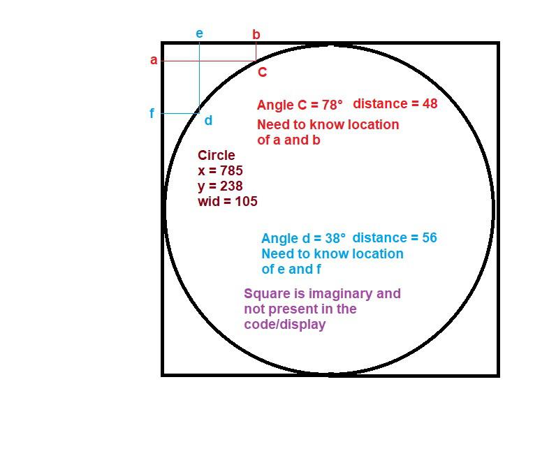 |
||||
| jirsoft Guru Joined: 18/09/2020 Location: Czech RepublicPosts: 533 |
When I didn't make any mistake... DIM INTEGER circle_x, circle_y,, x, y circle_x = 785 circle_y = 238 calc(x, y, 78, 48, circle_x, circle_y) ?x, y calc(x, y, 38, 56, circle_x, circle_y) ?x, y SUB calc(xx AS INTEGER, yy AS INTEGER, angle AS INTEGER, distance AS INTEGER, cx AS INTEGER, cy AS INTEGER) xx = circle_x + SIN(RAD(angle)) * distance yy = circle_y + COS(RAD(angle)) * distance END SUB Jiri Napoleon Commander and SimplEd for CMM2 (GitHub), CMM2.fun |
||||
| Paul_L Guru Joined: 03/03/2016 Location: United StatesPosts: 769 |
I wish they would stop teaching trigonometry by drawing triangles on the blackboard. Trigonometry is not defined by triangles! Trigonometry functions are properly named Transcendential Circular Functions. They are generated by repetitive circular motion. An excellent animation of the generation of the sin function is seen here. In this instance one picture is worth ten thousand words. https://www.mathsisfun.com/algebra/trigonometry.html If you think of the path of a single conductor in the armature of a generator tracing out a circle in a magnetic field it will be immediately obvious that the voltage generated by this circular motion must be a sinusoid. Assuming that the magnetic poles are at the top and bottom of the animated drawing then the maximum voltage (positive and negative) is generated when the individual conductor is moving perpendicular to the magnetic field at the top and bottom of the circle, zero voltage is generated when the conductor is moving parallel to the magnetic field. Finding the horizontal and vertical distance of a point on your circle from the center of the circle just requires multiplying the Sin of the angle by the radius of the circle. Paul in NY |
||||
| lew247 Guru Joined: 23/12/2015 Location: United KingdomPosts: 1709 |
They didn't actually teach us Trigonometry in the school I went to, maybe it's a US thing that it's taught or maybe they've started teaching it in the past 45-50 years edit: I take that back, I learnt about Pythagous when I was doing my TV and Electronics course years after school, but I'd forgotten It also didn't help that I left school at 15 Edited 2021-01-10 05:08 by lew247 |
||||
CircuitGizmos Guru Joined: 08/09/2011 Location: United StatesPosts: 1427 |
This can be broken into steps - don't try to make an all-encompassing formula. First you have already done one thing: You have offset the center of the circle from 0,0 to a coordinate somewhere in the visible area of the screen. You can't get away from that as a step. That is best done as the last step and it is cleanest to do separately from other calculations. You are not drawing at 0,0 on the screen, but perhaps at 200,200 (for example) so this offset should be done to your calculations. What you need to calculate is a lot of polar (vector/angle) to rectangular conversions based first at 0,0 before you offset them to the location on the screen. You are calculating screen x,y positions by converting your vector (circle radius) and angle. This is the polar to rectangular conversion effort. Your outside graphic placement is your circle radius plus a fixed bit. Your inside graphic placement is your circle radius minus fixed bit. https://study.com/academy/lesson/how-to-convert-between-polar-rectangular-coordinates.html Micromites and Maximites! - Beginning Maximite |
||||
TassyJim Guru Joined: 07/08/2011 Location: AustraliaPosts: 6538 |
You need to know which way is up. 'Normal' maths will have zero degrees facing to the right and positive angles going anticlockwise. You compass has zero degrees heading UP and positive angles going clockwise. Remember that in MMBasic, Y increases as you go down which is the opposite to how you draw it on graph paper. This looks like a good place to start and explains the conversion much better than I could. You then have to decide if you need to add 90 degrees and reverse the sign of the angle. https://www.mathsisfun.com/polar-cartesian-coordinates.html Jim Edited 2021-01-10 11:42 by TassyJim VK7JH MMedit |
||||
| TassyJim Guru Joined: 07/08/2011 Location: AustraliaPosts: 6538 |
Too hot to work outside today... OPTION EXPLICIT OPTION DEFAULT NONE DIM FLOAT n,x,y,r,a ',sr,sa DIM INTEGER c = 0 CLS ' first, we convert polar to rectangular ' then back to rectangular as a check ' first set assumes normal cartesian coordinate system TEXT 10,n/2,"angle x y r a (coord=0)" FOR n = 0 TO 360 STEP 30 polar2rect(x,y,100,n,c) rect2polar(x,y,r,a,c) TEXT 10,n/2+30, STR$(n,3)+STR$(x,5,2)+STR$(y,5,2)+STR$(r,4)+STR$(a,5,0) TEXT MM.HRES/2+x,MM.VRES/4+y,STR$(n,4) CIRCLE MM.HRES/2+x,MM.VRES/4+y,3,1,1, RGB(CYAN),RGB(CYAN) NEXT n CIRCLE MM.HRES/2,MM.VRES/4,3,1,1, RGB(RED),RGB(RED) ' c = 1 ' second set assumes compass bearings with north UP TEXT 10,MM.VRES/2,"angle x y r a (coord=1)" FOR n = 0 TO 360 STEP 30 polar2rect(x,y,100,n,c) rect2polar(x,y,r,a,c) TEXT 10,n/2+30+MM.VRES/2, STR$(n,3)+STR$(x,5,2)+STR$(y,5,2)+STR$(r,4)+STR$(a,5,0) TEXT MM.HRES/2+x,MM.VRES/4*3+y,STR$(n,4) CIRCLE MM.HRES/2+x,MM.VRES/4*3+y,3,1,1, RGB(CYAN),RGB(CYAN) NEXT n CIRCLE MM.HRES/2,MM.VRES/4*3,3,1,1, RGB(RED),RGB(RED) TEXT 10,MM.VRES-40,"" SUB rect2polar( sx AS FLOAT, sy AS FLOAT, sr AS FLOAT, sa AS FLOAT, coord AS INTEGER) ' rectangular to polar. coord: 0 = cartesian, 1 = compass ' angle in degrees ' Y increases going down ' if your MMBasic doesn't have ATAN2, substitute the user function ATN2() sr = SQR(sx*sx+sy*sy) sa = (360 + DEG(ATAN2(-sy,sx))) MOD 360 'if sa < 0 then sa = 360 + sa IF coord THEN sa = (450-sa) MOD 360 ENDIF END SUB SUB polar2rect( sx AS FLOAT, sy AS FLOAT, sr AS FLOAT, sa AS FLOAT, coord AS INTEGER) ' polar to rectangular. coord: 0 = cartesian, 1 = compass ' angle in degrees ' Y increases going down IF coord THEN sx = sr * SIN(RAD(sa)) sy = -sr * COS(RAD(sa)) ELSE sx = sr * COS(RAD(sa)) sy = -sr * SIN(RAD(sa)) endif end sub FUNCTION atn2(fy as float,fx as float) as float local float arctan IF ABS(fx) < 0.0000001 THEN arctan = 0 fx = 0 ELSE arctan = ATN(fy/fx) ENDIF IF fx > 0 THEN atn2 = arctan ELSEIF fy>=0 AND fx<0 THEN atn2 = PI + arctan ELSEIF fy< 0 AND fx<0 THEN atn2 = arctan - PI ELSEIF fy> 0 AND fx=0 THEN atn2 = PI / 2 ELSE ' fy< 0 and fx=0 atn2 = PI / -2 ENDIF END FUNCTION The two subs, rect2polar and polar2rect assume angles in degrees and standard computer display with Y increasing as you go down the page. The last parameter lets you change from 1=compass to 0=Cartesian. Not all versions of MMBasic have ATAN2 so I have included a function ATN2() Jim VK7JH MMedit |
||||
| lew247 Guru Joined: 23/12/2015 Location: United KingdomPosts: 1709 |
oh wow that truly is amazing thank you so so much |
||||
| johnd Newbie Joined: 22/10/2020 Location: United StatesPosts: 30 |
If 785,238 is the center of the circle and the diameter is 105 (radius=105/2), then a = 785 - 105/2, 238 - (105/2)*sin(78*pi/180) b = 785 - (105/2)*cos(78*pi/180), 238 - 105/2 e = 785 - (105/2)*cos(38*pi/180), 238 - 105/2 f = 785 - 105/2, 238 - (105/2)*sin(38*pi/180) |
||||
| lew247 Guru Joined: 23/12/2015 Location: United KingdomPosts: 1709 |
Thank you everyone for helping me I've been reading a lot and trying to understand it This was extremely helpful, it puts is in such a simple way that even I can understand it. However I still don't understand one thing This section of code Text 10,10,"NE",L,7,,RGB(1,1,1),RGB(134,174,230) Image rotate 6,4,30,30,cx%+(wid%-16)*Cos(.785),cy%-(wid%-16)*Cos(.785),45,1 Text 10,10,"SE",L,7,,RGB(1,1,1),RGB(134,174,230) Image rotate 6,4,30,30,cx%+(wid%-16)*Cos(.785),cy%+(wid%-16)*Cos(.785),135,1 Text 10,10,"SW",L,7,,RGB(1,1,1),RGB(134,174,230) Image rotate 6,4,30,30,cx%-(wid%-16)*Cos(.785),cy%+(wid%-16)*Cos(.785),225,1 Text 10,10,"NW",L,7,,RGB(1,1,1),RGB(134,174,230) Image rotate 6,4,29,29,cx%-(wid%-16)*Cos(.785),cy%-(wid%-16)*Cos(.785),315,1 Text 10,10," ",L,7,,RGB(134,174,230),RGB(134,174,230) ' clear text It prints NE,SE,SW and NW in the correct locations on the screen but the code is exactly the same for all 4 other than the angles which obviously tells it where to print the words. I wanted to add all the sub intermediate coordinates as well and tried to use the same code and add NNE by using Text 10,10,"NNE",L,7,,RGB(1,1,1),RGB(134,174,230) Image rotate 6,4,30,30,cx%+(wid%-16)*Cos(.785),cy%-(wid%-16)*Cos(.785),22.5,1 but it doesn't work Can anyone tell me why it doesn't and how do I work out how to place it? Edited 2021-01-11 21:22 by lew247 |
||||
| lizby Guru Joined: 17/05/2016 Location: United StatesPosts: 3784 |
Lew--you always need to say what kind of "doesn't work". PicoMite, Armmite F4, SensorKits, MMBasic Hardware, Games, etc. on FOTS |
||||
| lew247 Guru Joined: 23/12/2015 Location: United KingdomPosts: 1709 |
Sorry I keep forgetting you can't see what I'm thinking Easier to show you 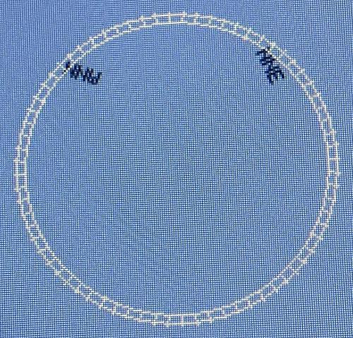 It still displays them at 45 and 315 degrees instead of 22.5 and 67.5 Text 10,10,"NNW",L,7,,RGB(1,1,1),RGB(134,174,230) Image rotate 6,4,29,29,cx%-(wid%-16)*Cos(.785),cy%-(wid%-16)*Cos(.785),22.5,1 Text 10,10,"NNE",L,7,,RGB(1,1,1),RGB(134,174,230) Image rotate 6,4,30,30,cx%+(wid%-16)*Cos(.785),cy%-(wid%-16)*Cos(.785),67.5,1 Text 10,10," ",L,7,,RGB(134,174,230),RGB(134,174,230) ' clear text |
||||
| lew247 Guru Joined: 23/12/2015 Location: United KingdomPosts: 1709 |
What I'm trying to understand is this If I know X AND angles 1,2,3 and 4 How do I calculate what Y is for each one? 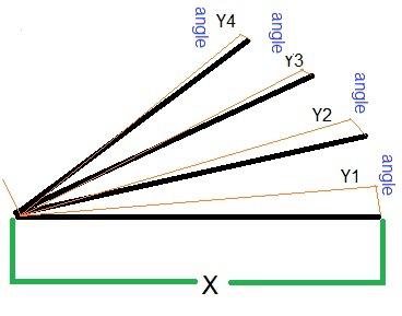 Edited 2021-01-11 23:32 by lew247 |
||||
| William Leue Guru Joined: 03/07/2020 Location: United StatesPosts: 411 |
Knowing X is not really needed or helpful. What you need instead of X is the length of the lines from the pivot point to the end of each line. If we assume that each of these lines is the same length, then it's easy: Let the point cx, cy be the pivot point. and r be the length of the lines. Then y = cy - r*sin(angle) The minus sign is because the direction of increasing Y is down. If your angles are in degrees, don't forget to use the rad() function to convert to radians before taking the sin of the angle: y = cy - r*rad(sin(angle)) -Bill |
||||
| johnd Newbie Joined: 22/10/2020 Location: United StatesPosts: 30 |
Excuse my crude quarter circle (of radius R), but the (x,y) coords for the angle (ang in degrees) is: ----\ --\ (x1, y1) <- want the coordinate at this location for the angle (ang1) _/ --\ _/ | / \ / ang | =============| R = radius x = R*cos(ang_deg * pi/180) y = R*sin(ang_deg * pi/180) So, in your diagram, X looks to be the radius, and the heights for Y1-4 would be y1 = X*sin(ang1 * pi/180) ... y4 = X*sin(ang4 * pi/180) Of course, in screen coordinates with Y increasing down the screen, you would subtract these Y values from the starting point. And the X locations on the outside of the circle would be (again with 'X' as the radius) x1 = X*cos(ang1 * pi/180) ... |
||||
| lew247 Guru Joined: 23/12/2015 Location: United KingdomPosts: 1709 |
Thank you  |
||||
| lew247 Guru Joined: 23/12/2015 Location: United KingdomPosts: 1709 |
I'm not getting it at all I was sure this would work It prints the new ones a the top of the screen Option explicit CLS RGB(134,174,230) Dim cx% = 785 Dim cy% = 238 Dim wid% = 105 Dim ang! = 0.087266463 Dim rad90! = 1.570796327 '90 degrees in radians compass_rose 625,475,75 Sub compass_rose cx%,cy%,wid% Local a% Text cx%+9,cy%+15-(wid%+22),"N",L,4,,RGB(1,1,1),RGB(134,174,230) Text cx%+9,cy%+15+(wid%+5),"S",L,4,,RGB(1,1,1),RGB(134,174,230) Text cx%+wid%+18,cy%+4,"E",L,4,,RGB(1,1,1),RGB(134,174,230) Text cx%-(wid%+5),cy%+4,"W",L,4,,RGB(1,1,1),RGB(134,174,230) Text 10,10,"NE",L,7,,RGB(1,1,1),RGB(134,174,230) Image rotate 6,4,30,30,cx%+(wid%-16)*Cos(.785),cy%-(wid%-16)*Cos(.785),45,1 Text 10,10,"SE",L,7,,RGB(1,1,1),RGB(134,174,230) Image rotate 6,4,30,30,cx%+(wid%-16)*Cos(.785),cy%+(wid%-16)*Cos(.785),135,1 Text 10,10,"SW",L,7,,RGB(1,1,1),RGB(134,174,230) Image rotate 6,4,30,30,cx%-(wid%-16)*Cos(.785),cy%+(wid%-16)*Cos(.785),225,1 Text 10,10,"NW",L,7,,RGB(1,1,1),RGB(134,174,230) Image rotate 6,4,29,29,cx%-(wid%-16)*Cos(.785),cy%-(wid%-16)*Cos(.785),315,1 Text 10,10,"NNE",L,7,,RGB(1,1,1),RGB(134,174,230) Image rotate 6,4,29,29,cx%-(wid%-16)*Cos(.785),cy% = cx%*sin(22.5 * pi/180) * pi/180),22.5,1 Text 10,10,"NNW",L,7,,RGB(1,1,1),RGB(134,174,230) Image rotate 6,4,29,29,cx%-(wid%-16)*Cos(.785),cy% = cx%*sin(67.5 * pi/180) * pi/180),67.5,1 Text 10,10," ",L,7,,RGB(134,174,230),RGB(134,174,230) ' clear text ' tick marks, every 5 degrees (360/5 = 72) For a% = 0 To 71 Line (cx%+15)+(Cos(a%*ang!)*(wid%-4)),(cy%+15)-(Sin(a%*ang!)*(wid%-4)),(cx%+15)+(Cos(a%*ang!)*(wid%+1)),(cy%+15)-(Sin(a%*ang!)*(wid%+1)),,RGB(WHITE) Next ' compass perimiter Circle cx%+15,cy%+15,wid% Circle cx%+15,cy%+15,wid%-4 End Sub I can't see why it isn't placing them where they should be 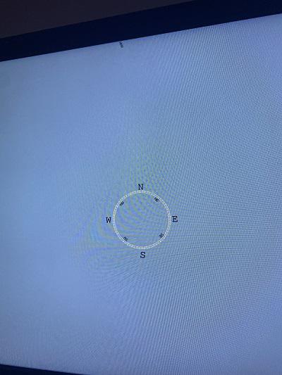 |
||||
| johnd Newbie Joined: 22/10/2020 Location: United StatesPosts: 30 |
In your last two Image rotate statements, you have cy% = cx%...., but I think the "=" should be a "-" or "+". Also, it looks like you have a double "*pi/180) * pi/180)" and I'm not sure what that last ')' even matches up to. I haven't run this code, but I'm sure the last two image statements are incorrect. You need something like: Image rotate 6,4,29,29,cx%+(wid%-16)*Cos(1.178),cy%-(wid%-16)*sin(0.393),22.5,1 for the NNE and Image rotate 6,4,29,29,cx%-(wid%-16)*Cos(1.178),cy%-(wid%-16)*sin(0.393),22.5,1 for the NNW I'm not positive this is correct (since I'm not running it directly) but it should be closer than what you had, especially with the '=' and extra "*pi/180)" code. note: in previous code 0.785 = 45*pi/180 and 0.393 = 22.5 *pi/180. and 1.178 = (45+22.5)*pi/180 |
||||
| The Back Shed's forum code is written, and hosted, in Australia. | © JAQ Software 2026 |
