
|
|
Forum Index : Microcontroller and PC projects : CMM2: Micro SD Card problems
| Author | Message | ||||
| Nelno Regular Member Joined: 22/01/2021 Location: United StatesPosts: 59 |
I have a RetroMax version of CMM2 from CircuitGizmos on which I had to replace the micro SD card socket. (note that RetroMax have micro SD sockets, not SD). This went not too badly the first time around, except I accidentally delaminated the two front solder pads by accidentally applying some leverage just after the solder had rehardened. This meant my card socket could easily bend upwards if not handled gently. Rather that repair the pads now, I was working on designing a custom 3d printable case that would also help to hold the socket against the board. Because of this I was doing a lot of handling of my RetroMax board to test fitment against against printed prototypes, etc. In the process when replacing the SD card I didn't hold it down and accidentally bent and broke some pins. Turns out this damaged some of the traces, too. So, having another 4 SD card sockets I just decided to fix it again. Unfortunately, this time it's not working. I've tried everything I can think of: - I've repaired a damaged trace from the data pin that I believe was ripped out or scraped off when the socket was bent - I tested for bridges vs all pins and the metal case - I verified the connections from every pin to its termination point on the processor - I've visually inspected the pins in the socket, though maybe I should take off the shielding to visually inspect there too - when the card is inserted, the card detect pin is correctly bridged with ground to indicate the card is inserted - insertion makes the CMM2's read access light go off (it is solid red before insert - not sure if that is expected) - after insert the access light blinks about once per second when the CMM2 attempts to read the card - I can see the clock pulse on the CLK pin every time the light pulses - voltage on the VDD pin appears to be about 2.4V. This is slightly out of spec which is supposed to be a min of 2.6V but my little handheld oscilloscope is not very good at showing me voltage levels and I've seen it read slightly low before. Duh... I should check this with my multimeter, too... - I do not see anything come off the data pin(s)... Only one should be used but I've checked all - the card read fine prior to the mishap and still reads fine now (yes, I've backed it all up) - I tried resetting the device by bridging pins 39 to 40. This seemed to do nothing, though - I pulled the battery to reset the 4K option RAM Still get the flashing light and a "Check Disk" message in the status bar. This is the spec sheet for the connector. I don't know if mine is exactly this brand but it matches the diagrams exactly: https://www.partco.fi/en/index.php?controller=attachment&id_attachment=1606 I'm a software engineer by trade with an electronics hobby, so I don't mind fixing (or breaking) things now and then, but this has me baffled for now. If anyone has any insights into what I might have missed, I'd appreciate the pointers. Edited 2021-01-28 13:29 by Nelno |
||||
TassyJim Guru Joined: 07/08/2011 Location: AustraliaPosts: 6538 |
There are a few lines to check. I used this spreadsheet when I put my first breadboard system together. The pin numbers refer to a full size card holder but the designations are the same. 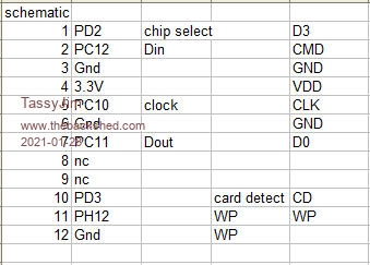 This image gives you the pinout for the microSD 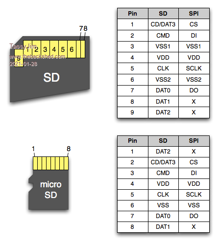 The pin numbers on the CPU are: PD2 144 PD3 145 PC10 139 PC11 140 PC12 141 PH12 89 On your board, WP is not available so PH12 (pin 89) will be tied to ground. Jim VK7JH MMedit |
||||
| Nelno Regular Member Joined: 22/01/2021 Location: United StatesPosts: 59 |
Thanks, I had tested all of those at some point but this inspired me to go back and do it again, and I found the problem. The first issue was the broken trace that was pulled off when I accidentally bent the card socket up, but that was indeed fixed. The remaining issue was that I had two pins that weren't touching the pads. They looked like they were touching but just had a little less solder on them. When I was testing for continuity I was putting the probe on the pad just next to the pin and not on the pin itself, so I mistakenly thought they were connected. I knew better, but that's what I get for doing things at 4 am when I'm half asleep. It's all working now. I will de-solder it this weekend after I have some high-temp epoxy come delivered, repair the delaminated pads, overcoat the fixed trace, and it should be good as new. Edited 2021-01-29 13:30 by Nelno |
||||
| TassyJim Guru Joined: 07/08/2011 Location: AustraliaPosts: 6538 |
That's good news VK7JH MMedit |
||||
| The Back Shed's forum code is written, and hosted, in Australia. | © JAQ Software 2026 |
