
|
|
Forum Index : Electronics : Time for a new Warpinverter build
| Page 1 of 10 |
|||||
| Author | Message | ||||
| rogerdw Guru Joined: 22/10/2019 Location: AustraliaPosts: 792 |
Well I've finally decided to build a Warpinverter. I've been messing about for far too long and it's time to make a commitment and get on with it. My initial thoughts are to use a pair of 3kW AeroSharp toroid cores for the main tx ... another 3kW core for #2, 1.5kW core for #3 ... and a smaller core I stripped from a failed device for #4. I also checked on prices from AEM Cores in Adelaide for a pair of cores 240mm OD, 120mm ID and 70mm high ... which makes them marginally bigger than the AeroSharp cores ... but with a bigger hole to allow for some spacing between the inner secondary winding and the core. That gives 4,200 sq mm cross sectional area. I haven't read anywhere here if that has been successful in reducing the capacitive effect that some of the earlier builds suffered from ... but I need to get started one way or the other. AEM quoted $169 each plus gst ... plus $60 freight ... all up $437.80 for the pair needed. I have three 3kW Aerosharp toroids ... but the cores are two different sizes One core is 205mm OD, 98mm ID and 70mm high While the other two cores are 190mm OD, 98mm ID and 70mm high Strangely enough, the bigger transformer was burnt out. The 205mm core gives 3,745 sq mm cross sectional area ... and the 190mm ... 3,220 sq mm. I did wonder if that unit had the wrong size transformer fitted. The boxes are clearly marked at 3kW ... but the bigger tx came from a different supplier to the 190mm ones. I also am considering removing 20mm from the centre of the #1 cores ... then adding a full 20mm to the outside from a spare core. I'm pretty sure I can work out a way to do it ... provided I can find an additional dead unit. I have 7kg of new 1.8mm wire plus a heap of secondhand 1.6 and 1.8mm. Not sure exactly which way to head for the switching ... whether using IGBTs or multiples of mosfets. I do wonder if I could actually use the original AeroSharp IGBTs for the middle two toroids. They are 600V at 50 amps ... PM50B6LA060 Mitsubishi full bridge devices ... and I have a few spares. https://www.mitsubishielectric-mesh.com/products/pdf/PM50B6LA060_n.pdf Tony also suggested Mitsubishi half bridge CM200DY-12H modules ... 600V 200A as an alternative in Haxby's thread ... perhaps for the biggest toroid #1. http://pdf.datasheetcatalog.com/datasheet/MitsubishiElectricCorporation/mXttwvw.pdf I still have not organised my forklift battery ... but figure I will aim for a voltage low of 44 volts like Tony advised for Mark ... and figure I could even try initially to run directly from solar panels like Tony showed could be done. And I'll have to save up for some decent capacitors too I suppose. I happened to find 24 x 47,000 uF 63 V Epcos electros on FB Marketplace (of all places) ... for $200 ... but understand I'll need at least 100 volt caps. Anyway, I've put it out there now ... there's no turning back.  Cheers, Roger |
||||
| Warpspeed Guru Joined: 09/08/2007 Location: AustraliaPosts: 4406 |
If you do decide to get the new AEM cores, no need to order two, just order one big one. They do not carry stock of anything. Every order is wound individually, so you can order a single large core with any dimensions you wish. Everyone seems to struggle with a 100mm hole, you could order one with a 110mm or 120mm hole. That may actually work out a bit cheaper, especially if you can pick it up personally. Cheers, �Tony. |
||||
| rogerdw Guru Joined: 22/10/2019 Location: AustraliaPosts: 792 |
I had been going on what their website said (that 70mm was the widest) ... but I sent an email and they tell me the maximum width they can wind is 100mm. (prompt reply too ... had an answer in 3 mins!!) Bit of a pity, would have made it much easier to deal with as one core ... and likely cheaper too as you suggest. I probably would pick it up too ... save $60 ... though I avoid trips to the city as much as possible. Every time I do go, I'm reminded of why I live in the country. Yes, that makes a lot of sense. Especially if I need a space between the core and the secondary winding. What sort of spacing would you think I should aim for ... 5 or 10mm perhaps? I don't know much about tx or toroid theory ... but is it best to keep the cross sectional area as square as possible ... or is it just the total area that is important? Reason for asking is that I could go wider than 70mm each ... or go bigger in diameter to reach the desired cross sectional area. Cheers, Roger |
||||
| Warpspeed Guru Joined: 09/08/2007 Location: AustraliaPosts: 4406 |
Probably 5mm around the bare core, and another 5mm between primary and secondary. This idea has not yet been proven. Mark has spaced his windings, but is yet to do final testing, but he is very close to that now. We will be looking for very high and narrow current spikes in the primary. 100mm core height might be enough if you make the core fatter (larger outside diameter). Its a case of juggling all the numbers. A skinny core requires more turns, but if both the inside and outside diameters are larger, there will be more room for extra turns. Cheers, �Tony. |
||||
| rogerdw Guru Joined: 22/10/2019 Location: AustraliaPosts: 792 |
That's very helpful thanks Tony. I know it hasn't been proven yet but I have to make a start sooner or later ... and very handy to have some numbers to aim for. I created a couple graphics showing the cross sectional area of 2 stacked 3kW Aero-Sharp toroids ... one pair at 190mm OD and another at 205mm OD ... and the circumference of the winding area. Then another graphic showing increasing diameters at 100mm high. 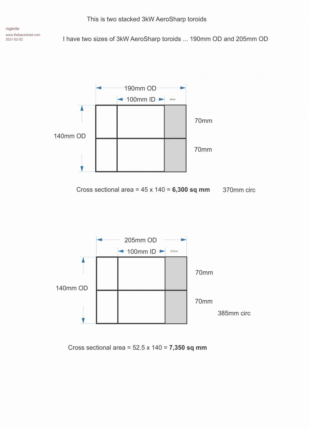 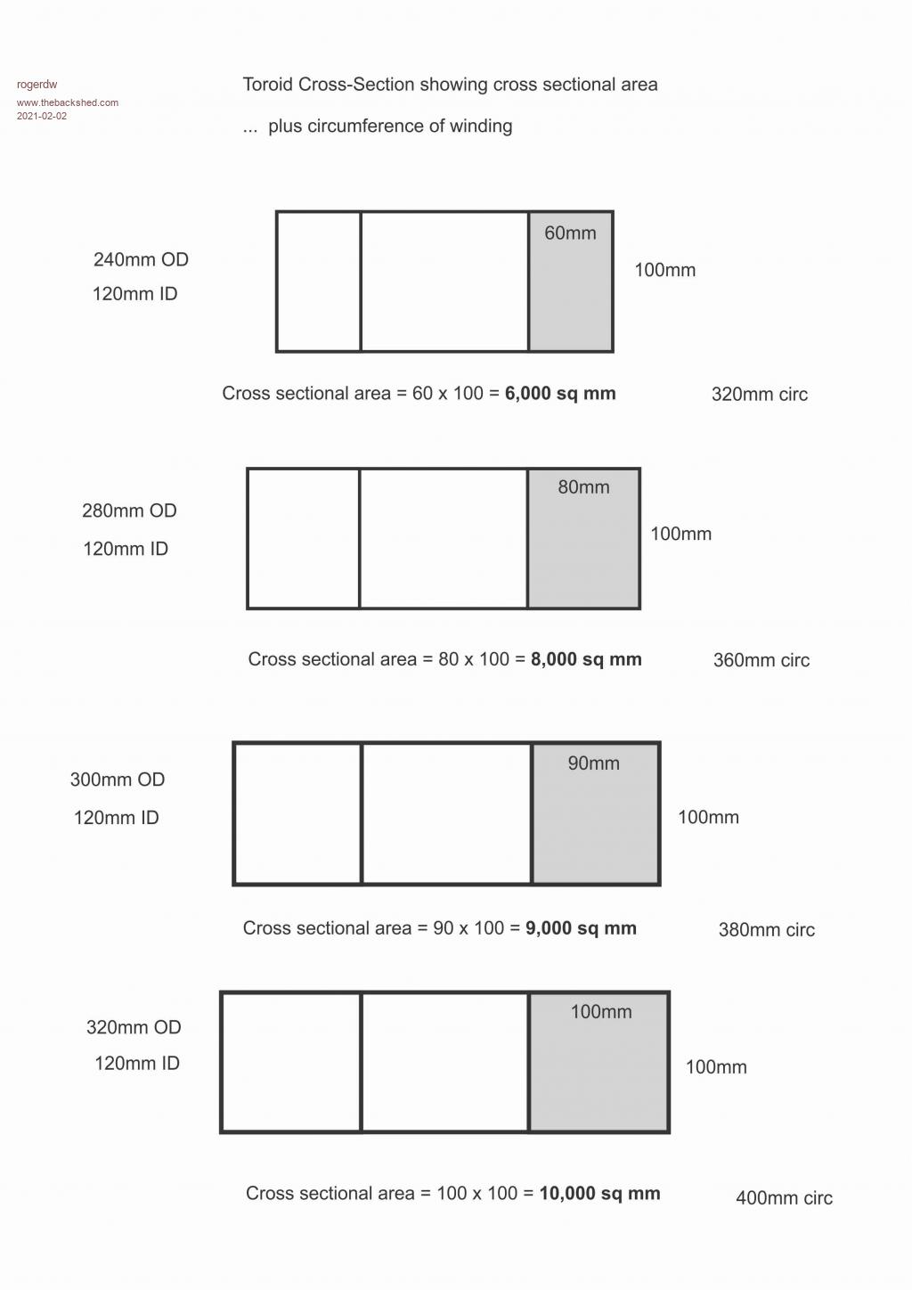 Cheers, Roger |
||||
| Warpspeed Guru Joined: 09/08/2007 Location: AustraliaPosts: 4406 |
O/k, let's think about this logically. We start with a 120mm hole, and if we allow for equal copper areas primary and secondary, the secondary should fill up the hole, leaving 70% of the original hole remaining (actually 0.7071 or root two). So that we end up with a hole 84mm diameter after winding on the secondary. We have 18mm + 18mm available for the secondary (120mm - 84mm = 36mm) and we are going to lose 5mm with our spacer. So 13mm depth of copper on the secondary. If 1.8mm wire is used, six layers might be possible in practice. 1.8mm wire is 2.5mm squared. At four amps per mm/sq ten amps per layer. Wow !! However many layers we can fit, the last final layer of the secondary will have a diameter of 84mm, and a circumference of roughly 263.9mm. That is going to be our tightest secondary layer, so that sets the limit for all the preceding secondary layers. With 1.8mm wire that would in a perfect world be about 146 turns. My guess is a genius may be able to get about 135 turns on max on the tightest last layer. Anyhow, lets look at how many turns we actually need. We go to our trusty Flux calculater : https://daycounter.com/Calculators/Max-Flux-Density-Calculator.phtml and plug in the numbers: Secondary voltage 225v for the largest transformer. Frequency .00005 Mhz (four zeros for 50Hz) Number of turns by trial and error = 101 turns Core cross section 10cm x 10cm = 100 cm square Press the magic button and we get 10,035 Gauss = 1.0035 Teslas our target flux density. So five or six layers of 1.8 wire and 101 nominal turns will fit very easily. We may need to go up or down a few turns to get the turns ratio exactly right, but 101 +/- a few turns would be our initial first guess. In fact you could probably go down to a 110mm hole. Should be capable of fifty amps easy for the whole inverter or around 11.75 Kw. Maybe that is too big for you ? If so, rinse and repeat with a smaller core, maybe 90mm x 90mm cross section ??? And fewer 10 amp layers. But remember, a smaller core requires more turns, and the walls can quickly close in on you. Smaller is always cheaper, and easier to work with. If you go through this exercise a few times, with a bit of guessing about what will fit, being EXTREMELY conservative, its possible to come up with some numbers that look reasonable. Edited 2021-02-02 15:13 by Warpspeed Cheers, �Tony. |
||||
renewableMark Guru Joined: 09/12/2017 Location: AustraliaPosts: 1678 |
You need to look at what you are building as a power source for a home that you can repair. Compare that to commercially available units. The specs of the machine you are going to make would be a bloody expensive commercial unit. So if you put it in that context don't worry too much about the cost of the bits. If someone told me that bigger cores could be wound that cheap with a 120mm centre I'd jump on that. $437 for the big transformer cores is really good. That will save you a lot of heat ache. Do the smaller ones first though, you really do get better with each one. I'll be testing mine soon and will be able to swap out the standard large transformer so we can see the difference of the two designs (i forgot what they were now hahaha) Cheers Caveman Mark Off grid eastern Melb |
||||
| rogerdw Guru Joined: 22/10/2019 Location: AustraliaPosts: 792 |
Thanks Tony, that's taken me a while to get my head around all those figures. So I did rinse and repeat with gradually smaller toroids ... but that raised a few more questions. #1 It sounds like it's important to be able to fit each secondary winding in (only) one layer ... and not have to have any turns from the first way around, end up on top of the first layer? #2 I recall you saying elsewhere that it is important to spread the turns out evenly around the core eg in your figures above with 5 or 6 layers of 101 turns ... the first layer could fit approx 170 turns ... ... but I should space the turns out so that 101 turns end up filling up all that layer ... keeping the ends far enough apart to prevent potential tension ... then put a layer or two of poly tape ... then repeat. I am assuming that is with five secondary windings (not 6) ... and how did you come at the 11.75Kw for the whole inverter? Thank you. Cheers, Roger |
||||
| rogerdw Guru Joined: 22/10/2019 Location: AustraliaPosts: 792 |
Yeah, I have to agree. When I first started looking at all these options I was figuring that if I didn't spend too much money ... and I couldn't get one going and it blew up ... then I wouldn't be too concerned. But now that I am 100% convinced of the viability ... why would I take a risk with dodgy bits or secondhand wire ... at least for the main toroid. Just pay the money and make it once, properly. Certainly the smaller toroids should be easier going and not so hard to replace if they don't work out. When AEM quoted $169 each to supply cores I was wondering why no one else had done that ... but add gst and multiply by two plus freight ... it does add up.  Having said that, with Tony's comments above I may well be better off using just one core from AEM ... albeit a much bigger one ... so will be interesting to see a price when I narrow down the size I need. Haha yeah, I've been hanging out forever to see your results. If I recall right, your last wind was with the primary wound first ... closest to the core. I was hoping to avoid that as it sounded a lot more difficult than the other way around ... and with my lack of experience, I need easier. ... and I doubt I will ever get to your level of toroid winding skill. And I have to thank you too ... you've been a great inspiration to me to see how someone without an electronics background could come in and keep persevering until they get great results. Well done man. Cheers, Roger |
||||
| Warpspeed Guru Joined: 09/08/2007 Location: AustraliaPosts: 4406 |
What limits us (and the final power rating) will be how many ten amp secondary windings we can fit onto the core in the available space. There are two main considerations, leakage inductance and winding insulation. The "nicest" solution is to space each winding as evenly as possible right around the toroid, and layer the winding over the top of each other, with a suitable gap between the start and finish of each winding. That produces the flattest windings, with the best insulation, or lowest voltage between adjacent turns on consecutive layers. By spacing the turns evenly around the core, that gives us the best highest possible primary to secondary coupling. If for example, the secondary were bunched up over only half the core circumference, the sneaky flux always finds the easiest path, and that might be through the air, instead of through the section of core with the secondary wound on it. By evenly spacing the turns it tends to reduce flux leakage, and improves voltage regulation at very high loads. Yes indeed, the first layer has a huge circumference. The second layer, due to the magic of circles, and geometric rules, will fit exactly six turns less than the first layer. Third layer, twelve turns less than the first layer. By the time we get to a sixth layer, it would be thirty six turns less, or about 134 turns perhaps. So its an easy short cut to just assume or final layer will be very roughly where our minimum final allowable sized hole will be, about 70% of the original starting hole diameter. Yup, say 10mm to 15mm between the start and finish of each layer. A very thin layer of insulation, then the next layer. Just keep going until you hit 70% of the original hole diameter. As Mark says, once you have done this once, you will always think of how it could have been done better, or more easily. The next one will be much nicer and take far less time. Its well worth spending the time to think the whole thing right through, and dont be too ambitious. What you think will fit, never quite works out that well, but it does all get easier with a little practical experience to fall back upon. Yes, being conservative. The wire never goes on dead flat, it always bulges a bit, so how many ten amp layers you can fit depends on the final current rating. Now the largest transformer needs to generate a 225 volt square wave on the secondary at the lowest dc input voltage, and if we assume five layers and 50 amps that would be 225 x 50 = 11.250 KVa for that transformer. But the Warpverter has four transformers that TOGETHER create a nominal 235 volts rms. 225v + 75v + 25v + 8.3v = 333.3v peak. 333.3v peak x .7071 = 235.6v rms. Our secondaries will each be capable of running at 50 amps rms current, to produce a 235v rms output voltage = 11.75 Kva from the completed Warpverter. The whole thing uses up a lot of copper and iron to do what it does. No 1 transformer 11.25 Kva No 2 transformer 3.75 Kva No 3 transformer 1.25 Kva No 4 transformer 0.417 Kva. A total of 16.7 KVa worth of materials for an 11.75 Kva rated inverter. Its just not economically viable as a competitive commercial product if all the materials have to be bought new to wind these transformers. But for home brewing with secondhand materials it will produce a bullet proof inverter of very high power for significant less cost than anything you could buy commercially. Edited 2021-02-03 04:04 by Warpspeed Cheers, �Tony. |
||||
Haxby Guru Joined: 07/07/2008 Location: AustraliaPosts: 418 |
Are there any issues if we wind two smaller transformers (or more) for each inverter and parallel them? Obviously we would have to wind them within a volt of each other or less, but any other issues? It would be easier to handle when winding, and easier to move around instead of one giant lump of copper. |
||||
| Warpspeed Guru Joined: 09/08/2007 Location: AustraliaPosts: 4406 |
You are a dangerous man Phil. Its not good paralleling windings, unless they are wound on the same core. One turn difference lets the smoke out. It acts similarly to a shorted turn. It can be done safely, and two or more transformers can be made to load share, but if you parallel the windings on one side, the windings on the other side must be connected in series. I did this on one of my early Warpverters, I used a commercial 25v transformer for 25v. Then for 75v, I paralleled up the primaries of three similar transformers, then connected the secondaries in series for 75v (and three times the power). That worked fine. Cheers, �Tony. |
||||
| Warpspeed Guru Joined: 09/08/2007 Location: AustraliaPosts: 4406 |
Not sure about that... Smaller cores require a lot more turns for the same voltage. So hypothetically, which would be easier, winding 300 turns onto a single large core, or winding 400 turns (twice) onto a pair of smaller cores. It might be easier to move around, but vastly more time and frustration will be involved. Going the other way, using oversized toroids, fewer turns involved, much more room to work in, and much less cussing and swearing, and fewer sore fingers. Cheers, �Tony. |
||||
| Haxby Guru Joined: 07/07/2008 Location: AustraliaPosts: 418 |
Since the very very large cores are cumbersome to wind, there is a risk of damaging the windings while making them or while moving them around. If I were to do it, I'd consider winding 4 identical independent 75v transformers. I'd try to set up my workbench and jigs and templates just for the one type of transformer. Say the 3kw aerosharp core. That's heavy enough for me! Then use 3 of them in series for the large inverter and 1 for the medium one.... |
||||
| rogerdw Guru Joined: 22/10/2019 Location: AustraliaPosts: 792 |
That was very helpful thanks Tony. Fills in a lot more gaps in my lack of knowledge on transformer theory and practical application. Good to have some actual numbers too for the gap between the ends of the windings ... and the likely number of turns reduction per layer. Knowing that, helps with planning and also making sure I don't allow myself to take short cuts thinking I'll get away with it. Keeping all the windings on one layer certainly 'feels' better too. I kept picturing how jumbled and messy it would get if there was say one and a quarter layers per winding ... and by the end of it there'd be a huge mess with a fair chance of breakdown between the layers. It seems I should tackle the smaller toroids first to get in some practice, but I still need to plan well enough to know just how many secondary windings I will fit on all of the toroids. No point having 6 layers on #1 and not being able to fit 6 on all the others. In determining the bare toroid size, in normal commercial manufacturing I assume they go for the absolute least size they can get away with, simply to keep the build as cheap as possible. In our scenario, are there any major drawbacks if we use a core that ends up bigger than necessary ... other than cost and weight and quantity of wire of course? Cheers, Roger |
||||
| Warpspeed Guru Joined: 09/08/2007 Location: AustraliaPosts: 4406 |
That is certainly possible, it simplifies final packaging as well. I used 300 watt commercial toroids in mine with 230v primaries. Main transformer not needed because I was switching +/- 225v dc directly. Then 3 x 300watt transformers = 900 watts Then 1 x 300 watt transformer And 1 x 100 watt transformer (removed for another project in the picture below) 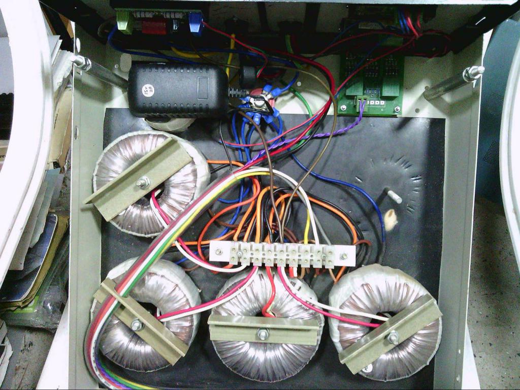 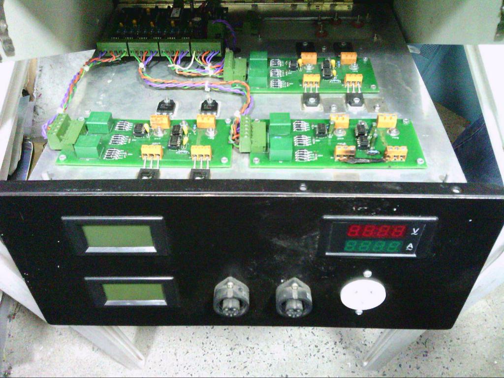 I would not recommend anyone doing it this way. Having no large transformer can send 225v dc to your house appliances if you have an inverter failure. That happened and did a lot of damage. Never again !! Edited 2021-02-03 09:49 by Warpspeed Cheers, �Tony. |
||||
| Warpspeed Guru Joined: 09/08/2007 Location: AustraliaPosts: 4406 |
All your transformers need to be designed for the same secondary current. The smallest toroids need fewer secondary turns because the voltage is lower. This needs some thought, because the largest transformer will almost always be a step up transformer. The smaller transformers may usually all or mostly be be step down transformers. Always put the highest voltage winding on first, there will be the larger number of thinner turns and it makes for a flatter winding over which to put the second winding. If you put the fat wire on first, it leaves a very lumpy winding which is a real bugger to wind over top of with the thinner wire. So for the big tranny, the secondary goes on first. The others, the primary will probably go on first, because it has the larger number of turns. Take for example the smallest transformer 48v to 8.3v (assuming 48v) The 8.3v winding will need to carry 50 amps and have relatively few turns. Solid round wire may be more practical, or you could use five strands of the 1.8mm wound on together in a bundle. The lightly twisted bundle will be much easier to work with than trying to plan five layers where relatively few turns are involved. And the risk of insulation breakdown is lower, as there will always be less than 8.3v between any wires that do cross each other. Commercial designs are all driven by profit. The less steel and copper, the lower the cost to make it. But the resulting transformer will run very hot and have a very high idling power. It will have a higher power rating for its size though. We want the lowest practical idling power for an inverter application, and we don't want excessively high running temperatures that might lead to a shortened life. Much less chance of buzzing too at lower flux densities. By choice, we run a much lower current density in the wire (lower losses, less heat) and a lower flux density in the core (lower idling power). So we make something huge out of recycled materials, and end up with a much more efficient and reliable but rather large transformer. Anything running off the grid, idling power is usually of no practical concern, especially if the transformer always runs full loaded. But if running 24 hours off a battery with light intermittent loading, the Kwh of idling power can sometimes exceed the Kwh of 24 hours of genuine load ! Its much much more cost effective to spend your money on copper and steel, than in the extra battery amp hour capacity required to keep your transformers warm and buzzing. Edited 2021-02-03 10:46 by Warpspeed Cheers, �Tony. |
||||
| Haxby Guru Joined: 07/07/2008 Location: AustraliaPosts: 418 |
Was the 225v unregulated directly from solar panels? That's a nice trick. A circuit to monitor unregulated DC and shut down wouldn't be too hard to add. I'm interested to know what blew up in your house when DC was applied? Were you home at the time? I guess the dumb smpsu appliances and resistive loads would be ok, but any power supplies with power factor correction would fry? As would induction motors and transformer based appliances. |
||||
| Warpspeed Guru Joined: 09/08/2007 Location: AustraliaPosts: 4406 |
I used eight panels in series to generate nominally 240v dc at the max power rating, but under no load it went to almost 300v. That dc went into three 2Kw switching power supplies to generate +/- 225v regulated. At that time, a way to use multiple lookup tables to regulate the actual Warpverter itself had not occurred to me. That particular Warpverter used a single 1K x 8 lookup table and the dc going into it was very tightly voltage regulated. I have been building these Warpverters for several decades now, and what you now see has very slowly developed and matured over a very long time. At this stage, I am 100% happy with it, and do not plan any other changes or upgrades. Just concentrate now on helping others to get started. The basic hardware version works fine, but there is plenty of scope for people to develop a software driven version, which now seems to be happening. That is something that is way out of my own skills range. I am a hardware power electronics guy, not a software magician. Before I retired I have worked with some really smart software people that had absolutely no interest at all in how the hardware worked. I am just as disinterested in their flow charts and subroutines as they are in the hardware. Together we have completed some pretty large and amazing commercially successful projects. The sales and marketing guys are another alien species that do things I have absolutely no interest in. Its all teamwork !!! Edited 2021-02-03 12:07 by Warpspeed Cheers, �Tony. |
||||
| rogerdw Guru Joined: 22/10/2019 Location: AustraliaPosts: 792 |
I had no idea that's how they worked it out. Makes sense now you've explained it. Ok, so if I order a 300mm OD x 120mm ID x 100mm high for Tx #1 ... that will give a cross sectional area of 90cm sq ... and if I use 44V as my lowest voltage ... The online calculator gives 112T for the Secondary 112 x 44/225 = 21.9 ... so 22T for the Primary Tx #2 ... a 3kW toroid ... cross sectional area of 36.75cm sq The online calculator gives 92T for the Secondary 92 x 44/75 = 53.97 ... so 54T for the Primary Tx #3 ... a 1.5kW toroid ... cross sectional area of 26.08cm sq The online calculator gives 43T for the Secondary 43 x 44/25 = 75.68 ... If drop to 42T for Sec ... 42 x 44/25 =73.92 ... so 74T for the Primary I haven't fully unwound my #4 Tx so not sure of the dimensions yet. I wasn't really aiming for ridiculous levels, but if I'm going to do this I'd rather do it just the once and do it well. It sounds like I should be able to fit 6 layers for each of the secondary's ... so that's 60 amps. Phew!!! Am I on the right track Tony, or am I off in the scrub somewhere? Cheers, Roger |
||||
| Page 1 of 10 |
|||||
