
|
|
Forum Index : Microcontroller and PC projects : MM Plus - Keyboard Connection
| Author | Message | ||||
| circuit Guru Joined: 10/01/2016 Location: United KingdomPosts: 305 |
I have a keyboard connection to a MM Plus in the prescribed manner and it works fine with a standard PS2 keyboard. The latter are becoming somewhat scarce and therefore I tried connecting a contemporary USB keyboard using an old Microsoft USB-PS2 adaptor as in this illustration. It works perfectly! 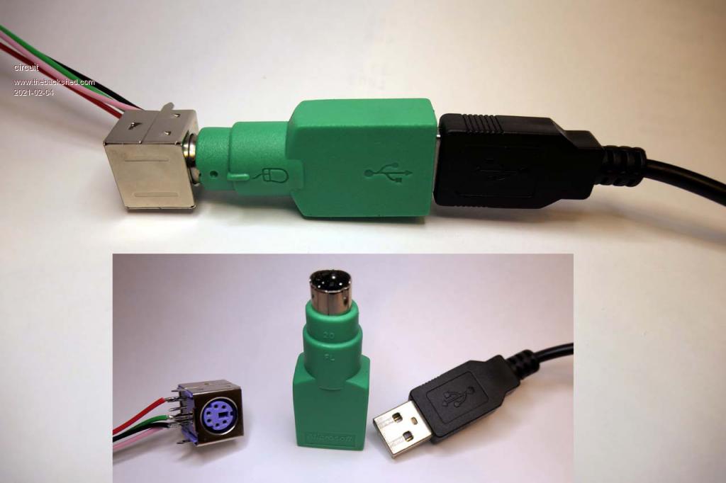 My question is what is going on in the adaptor? Is it in anyway active or is it just a wiring pass-through? I am hoping that the latter is the case and that I might be able to cut off the USB plug and just wire a four-pin molex connector instead. If the adaptor is in anyway active, what components would I need on my MM Plus motherboard to replicate its function? |
||||
| Zonker Guru Joined: 18/08/2012 Location: United StatesPosts: 772 |
I don't think there is anything going on inside the adapter... Just a wiring pass-through as you have said... just change the plug... Should be ok...  |
||||
| circuit Guru Joined: 10/01/2016 Location: United KingdomPosts: 305 |
What puzzles me is that the PS2 keyboard connections to the MM+ are "keyboard clock" and "keyboard data". USB lines are "Dataline positive" and "Dataline negative". How do these line up? |
||||
| CaptainBoing Guru Joined: 07/09/2016 Location: United KingdomPosts: 2171 |
As you and Zonks have already said, there is nothing clever inside the green jobby, the work is being done by the keyboard controller. "early" USB keyboards were auto-sensing. There was always the intent that such controllers would be stop-gap during the transition but it is only software so if it is costing nothing... a lot of modern keyboards will still support PS2 through such an adapter - evidently legacy software/module includes with the manufacturers either deliberately or just no-one has paid to have a turf-out/do-over. I wouldn't expect it to last forever. My company had a big IT rationalization day a couple of years back and I stockpiled a number of HP PS2 keyboards. They were going for recycle purely because they were PS2, nothing else wrong with them. I snagged six of the cleanest, complete examples and stashed them in long-term storage (loft of workshop). I may never need them but you never know... don't take up much space. Edited 2021-02-05 01:03 by CaptainBoing |
||||
| circuit Guru Joined: 10/01/2016 Location: United KingdomPosts: 305 |
Thank you - that clarifies things enormously. So, upon detecting a clock signal the keyboard is reconfiguring itself so that the USB wiring "data minus" line becomes the clock line. Excellent! Out will come the wire-cutters and the "gang of three" will be reduced down to a simple four pin Molex. I was thinking that a note to this effect would be helpful in the MicroMite Plus manual; it is generally much easier to source a USB keyboard than a PS2 keyboard. The problem would be trying to establish if the keyboard actually had the autoswitch firmware on board if one was buying new. |
||||
| lizby Guru Joined: 17/05/2016 Location: United StatesPosts: 3782 |
I'm trying to understand what this signifies. If you have an older USB keyboard which is likely to have the auto-switch firmware, you can connect USB "data minus" to a keyboard clock pin on the ARMmite F4, and USB "data plus" to the keyboard data pin, and all will automagically work? That will be easy to try with a USB breakout board if true. PicoMite, Armmite F4, SensorKits, MMBasic Hardware, Games, etc. on FOTS |
||||
| vegipete Guru Joined: 29/01/2013 Location: CanadaPosts: 1179 |
Before you start hacking plugs off, why not change the PS/2 jack to a USB jack? Also, my experience with mice and the CMM2 suggests that pull-ups on the 2 signal lines may be required to put a dual mode device into PS/2 mode. 2.2K, 4.7K, 10K ohm all seem to work. I've used 2.2K pull-ups to 5 volts - make sure the 'mite pins can handle it! Visit Vegipete's *Mite Library for cool programs. |
||||
| circuit Guru Joined: 10/01/2016 Location: United KingdomPosts: 305 |
Whoops! Sorry, I think I got that the wrong way around; I think that it is the "Data Plus" that connects to the clock pin of the MicroMite Plus- I am still tracking out the wiring through the converter. With respect to the pull-up resistors, in the MMPlus manual Geoff indicates that weak pull-ups are invoked (I presume with the "OPTION KEYBOARD language") and of course the pins designated for the keyboard are 5 volt tolerant. I have not checked out the situation with the ARMITE F4 - the sparsity of documentation is an issue. Given that Lizby is raising the question, I presume that we are talking of the STM32F407VET6 board. Is there a listing of the OPTIONS available for this board? I seem to have missed this but would much appreciate a pointer to one if it exists. |
||||
| lizby Guru Joined: 17/05/2016 Location: United StatesPosts: 3782 |
Thanks for the correction re USB keyboard to PS2 connections. I'll try this with a breakout board, but maybe not until tomorrow. Yes, STM32F407VET6 board. I don't think so for OPTIONs. It's the H7 manual--try it and see, then go back to the MM Plus manual, and then back to the Micromite manual. PicoMite, Armmite F4, SensorKits, MMBasic Hardware, Games, etc. on FOTS |
||||
TassyJim Guru Joined: 07/08/2011 Location: AustraliaPosts: 6538 |
Correct - PS/2 clock connects to USB D+. Most PS/2-USB converters include two 4.7k pullup resistors but that can vary. Jim VK7JH MMedit |
||||
| paceman Guru Joined: 07/10/2011 Location: AustraliaPosts: 1329 |
I've never understood all this either, I assumed the different 'electrical connections' mandated that each type of keyboard (PS2/USB) would need different 'electrical connections' in the computer/controller it's plugged into. I agree with @circuit - it would be a very good idea if this discussion was condensed and added to the MM+ Manual, also to the CMM2 Manual. Greg |
||||
| Geoffg Guru Joined: 06/06/2011 Location: AustraliaPosts: 3362 |
I never quite understood these adapters myself - however this discussion has cleared the air somewhat. But I cannot see that much needs to be added to the manual. I could say something like "Some USB keyboards come with a PS2 adaptor and the combination may work with the MM+". Not very informative. I certainly don't want to turn the manual into a tutorial on how PS2 adaptors work. Geoff Geoff Graham - http://geoffg.net |
||||
| circuit Guru Joined: 10/01/2016 Location: United KingdomPosts: 305 |
Quite understood - especially as the convolutions of all this appeared as this thread continued. Just to confirm the whole picture; Some USB keyboards can be connected to the MicroMite Plus whether not they came with a USB-to-PS2 adaptor; I have tried three USB keyboards that are available to me and they all work fine with the MicroMite Plus through the MICROSOFT adaptor. They are all original equipment to their parent PC. The Microsoft USB-PS2 Adaptor does indeed have 4.7K pullups on both the D+/Keyboard Clock and the D-/Keyboard Data lines. Acknowledging @Tassyjim, not all the USB-PS2 adaptors have the pullups and they do not work without the optional 4.7K pullups on the MM+ side. I tried a Kensington adaptor and it does not have pull-ups. Therefore, forget the adaptor. To determine if any USB keyboard can function with the MM+, firstly make sure that the optional pull-ups are installed as on Page 45 of the MicroMite Plus manual. Connect the power leads and then Keyboard Clock to USB D+ and Keyboard Data to USB D- and set "OPTION KEYBOARD language". I guess that the closer the date of manufacture of the USB keyboard is to the withdrawal of the PS2 keyboard plug, the greater the chance of it working. Final question... if the USB keyboard does not have the capability to switch to PS2 mode, is there any possibility of causing damage to the keyboard? I can't think it likely, but I guess that there would be no harm in putting a 1K resistor in each line while trying things out just to be cautious. |
||||
| lizby Guru Joined: 17/05/2016 Location: United StatesPosts: 3782 |
Well, what I thought was an old USB keyboard (because I could see the USB plug), turned out to be a PS2 keyboard with the PS2-USB dongle. I plugged the usb end into a female usb breakout board and ran D+ to the F4 keyboard clock (PA15, pin 77) and D- to keyboard data (PD3, pin 84), set OPTION KEYBOARD US, and ran INPUT A$,B$. I typed "Now is" and "the time" and ? A$,B$ and got >Now is the time The Logitech "Internet 350" USB keyboard I tried did not work (but I didn't use any pullups or set internal pullups). PicoMite, Armmite F4, SensorKits, MMBasic Hardware, Games, etc. on FOTS |
||||
| phil99 Guru Joined: 11/02/2018 Location: AustraliaPosts: 3289 |
Re pullups for the CMM2, for safety try 3.3k to the 3.3V rail. Even though the keyboard is 5V for many 5V chips the high / low transition is around 2V so it might still work. It certainly works when connecting a micromite to an arduino. |
||||
| lizby Guru Joined: 17/05/2016 Location: United StatesPosts: 3782 |
If that purple socket fits into a PCB footprint like this:  Which pins (holes) are 5V,0V,kbd clock, and kbd data? And are the big pointy feet in line with the 4-pin row? If offset, by how much? (I.e., I can't find an eaglecad footprint.) Edited 2021-02-13 08:18 by lizby PicoMite, Armmite F4, SensorKits, MMBasic Hardware, Games, etc. on FOTS |
||||
OA47 Guru Joined: 11/04/2012 Location: AustraliaPosts: 1050 |
I decided to check through my collection of keyboards with usb connection that will support PS2 and other than a couple of Msoft versions I was delighted to find that some small flexible (roll up) keyboards that I purchased from the local Woolworths store for a couple of dollars do also work. 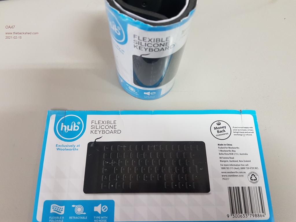  |
||||
| phil99 Guru Joined: 11/02/2018 Location: AustraliaPosts: 3289 |
Re PS2 PCB pads - have probed a socket and the results are (for your photo):- Top Left - Clock Bottom left - Ground Bottom Second from Left - Data Bottom Right - +5V Bottom Second from Right - NC Top Right - NC As for the location mounting pins, every brand is different so you will measure your socket. |
||||
| lizby Guru Joined: 17/05/2016 Location: United StatesPosts: 3782 |
Thank you very much. I have the pads labelled now on the PCB. PicoMite, Armmite F4, SensorKits, MMBasic Hardware, Games, etc. on FOTS |
||||
| The Back Shed's forum code is written, and hosted, in Australia. | © JAQ Software 2026 |
