
|
|
Forum Index : Microcontroller and PC projects : ArmmiteF4 firmware V5.07.00b1 - major upgrade
| Author | Message | ||||
| Volhout Guru Joined: 05/03/2018 Location: NetherlandsPosts: 5066 |
I am with TassyJim in that I do not want to spend $$ and much time trying to get to the bottom of this. Much of the information is on the internet (al be it that not everything may be true). But this is true: The SD card operation (data transfer) does not require pullups. In every phase of the transfer the lines are push-pull operated. This is not like I2C, where the pullup resistor has a actual function. The pullup resistors only have a function in transitions (while the software stack initializes IO pins), during insertion and extraction of the card, and during power up of the system. As such the values CAN (not saying MUST) relate to software (expecting logical stable levels at such and such moment). The pullup resistors should ensure logic high level. Therefore there will be a limitation in value due to humidity, leakage (input impedance) of pins. The boards we are refering to are probably designed by ST as demonstrator, before several chinees manufacturers made their derivatives. Designers of development boards know that these are used to develop software on. They typically do everything in their ability to make SW development smooth (i.e. they provide drivers), but also design the hardware so it is more or less monkey-proof. As such they may have decided to add a 10k pullup in the design. Even if the software activates the pullDOWN resistor, the SD card interface will still work. Finally: about SD card itself. On the Parallax forum someone measured several different SD cards, and found internal pullup resistors in the cards ranging from 20k ohm to 100k ohm (different brands, different memory sizes). Since the measurement method was not shown, this may not be 100% correct, but differences between cards will be possible. In my opinion adding resistors as pullups (in parallel to matherp's activation of the internal pullups in the F407) makes only sense when the whole unit is powered up. This prevents "floating signals" until the moment software takes the reign. Long story... PicomiteVGA PETSCII ROBOTS |
||||
| phil99 Guru Joined: 11/02/2018 Location: AustraliaPosts: 2619 |
To Andrew_G, Unfortunately I didn't take a photo. When Peter released that update and Goc30 found it worked I lifted the +3.3V bridge and tried it myself. It worked so well with my SD cards I removed the resistors. Tomorrow I will draw it in Paint and post it. Before the mods the SD card that had fewest problems was a Kingston 32GB, $11 at the local post office. (AustraliaPost - it's hard to guess where anyone lives, except TassyJim ;) |
||||
| matherp Guru Joined: 11/12/2012 Location: United KingdomPosts: 10250 |
Please find attached V5.07.00b8 ArmmiteF407.zip This includes a major piece of work from Gerry (disco4now) who has now implemented support for both variants of the 3.97" 800x480 IPS displays. To enable the display use: OPTION LCDPANEL DISABLE OPTION LCDPANEL IPS_4_16,orientation and then configure the touch if required OPTION TOUCH PB12, PC5 GUI CALIBRATE Gerry's code will automatically detect which variant of the display is connected and initialise it accordingly. He has also speeded up access to the displays considerably from the first release Many thanks Gerry - enjoy |
||||
| Andrew_G Guru Joined: 18/10/2016 Location: AustraliaPosts: 871 |
Peter, That latest version fixes my SD problems! Thanks! (what was the issue?) Now: - Files that span several pages scroll with the <ANY> key - Files works first and every time (so far) - I can Load Image . . . One does have to use Backlight to see the screen but once you've woken up to that its easy (why do the two methods differ? ie one is "0" high, the other is "0" low) Phil99 - thanks for your help but it appears to be not necessary to draw it out, unless you want to for posterity? (I'm about 5km East of Melbourne and the Post Office is not far from me, Jaycar and Officeworks.) Thanks everyone for your help. Andrew |
||||
| matherp Guru Joined: 11/12/2012 Location: United KingdomPosts: 10250 |
Which display is wrong? |
||||
| twofingers Guru Joined: 02/06/2014 Location: GermanyPosts: 1576 |
For the manual (about PWM): The manual says (p. 140) With MMBasic V5.07.00b8: > pwm 2,20000001,50 Error : 20000001 is invalid (valid is 1 AFAIK, the maximum frequency - the range that MMBasic allows - is 20 MHz . But a nice square wave goes up to 5 MHz, IMHO. The 20 MHz "square wave" looks very ugly. This is not meant as a criticism, just as an observation to better understand the features and capabilities of the F4. Edited 2021-03-19 22:12 by twofingers causality ≠ correlation ≠ coincidence |
||||
| lizby Guru Joined: 17/05/2016 Location: United StatesPosts: 3363 |
I seem to have lost an ILI9341_16. It flashed white then black upon power up. When I run gui calibrate, nothing shows up, but if I press a stylus at approximately the right places, I get a response at the prompt. GUI TEST LCDPANEL results only in an unchanging black screen. Tested on 2 different F4s. Flashed latest firmware. Screen was working yesterday. I removed it (powered off) and it didn't work when plugged back in (with power off). Any ideas about what I can do to test further or repair? PicoMite, Armmite F4, SensorKits, MMBasic Hardware, Games, etc. on fruitoftheshed |
||||
| Andrew_G Guru Joined: 18/10/2016 Location: AustraliaPosts: 871 |
lizby, Try "Backlight 50" Andrew |
||||
| lizby Guru Joined: 17/05/2016 Location: United StatesPosts: 3363 |
Now that's a great trick. All working now. How would it have gotten into whatever state it was in? (And what state was that?) That brought back to life another lcd that I thought was dead. On that one, however, "gui calibrate" presents a target, but pressing the center of the target with the stylus doesn't move you to the next target. Any more tricks regarding this problem? ~ Edited 2021-03-20 08:42 by lizby PicoMite, Armmite F4, SensorKits, MMBasic Hardware, Games, etc. on fruitoftheshed |
||||
| Andrew_G Guru Joined: 18/10/2016 Location: AustraliaPosts: 871 |
Hi Lizby, Peter's latest upgrade, I think, changes the Backlight from the ILI9341 approach (ie 0 is low to 100 high) to the SSD1963 approach of 0 is high, 100 is low (hence my comment above and Peter's rhetorical response). I bet you had your Backlight set to fairly high, which with the new version, became fairly low (so it was not visible). My suggestion of 50 was meant to at least be visible with either. (Sorry but I can't help with calibrate not behaving). Peter - I was commenting on the different conventions for the ILI9341 and SSD1963, as correctly reported in the manual (I admit I thought it was a typo) - not having a SSD1963 I can't test it. I would suggest that 0 = low and 100 = high is not too bad - but I don't see "rights" and "wrongs"? Another question: Does the new version (very much appreciated because it fixed my SD problem) mean that we no longer have to change jumpers on the SSD1963 displays? Cheers, Andrew Edited 2021-03-20 09:01 by Andrew_G |
||||
| phil99 Guru Joined: 11/02/2018 Location: AustraliaPosts: 2619 |
To Andrew_G, Glad that is sorted. Peters wizardry works wonders. It's now redundant, but I thought of an easier option. On the V33 board 4 pullups for the Debug Interface are in an SMD DIL package. Two of them in a size that matches the SD socket pin spacing would have been much easier. It would just require clipping off the unneeded pins. A bit of hotmelt glue would keep it all in place. 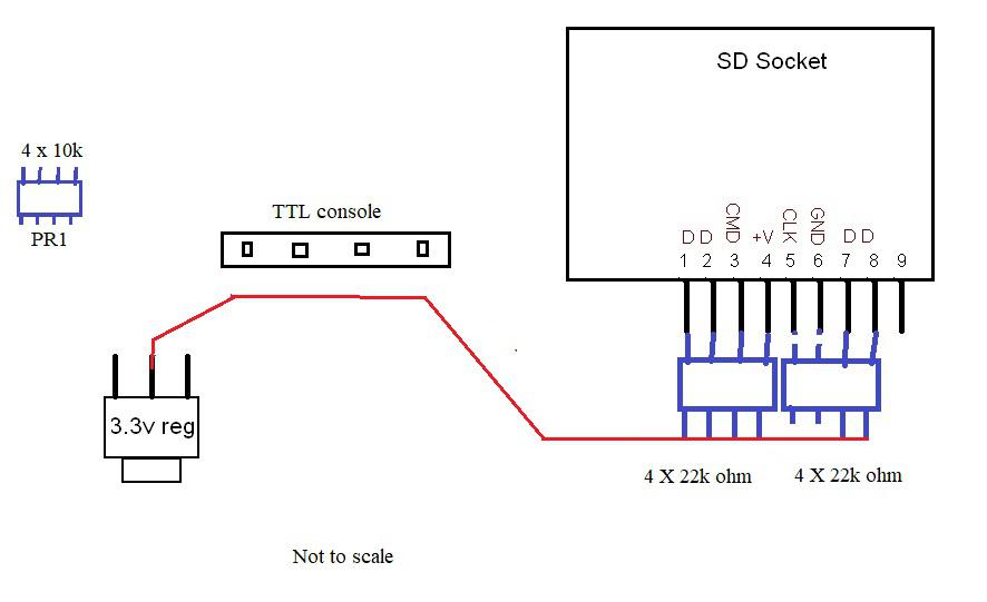 |
||||
| Andrew_G Guru Joined: 18/10/2016 Location: AustraliaPosts: 871 |
Thanks Phil - that is most helpful. Cheers, Andrew |
||||
disco4now Guru Joined: 18/12/2014 Location: AustraliaPosts: 1000 |
The SSD1963 displays must still be set for PWM control. The brightness is controlled by the driver sending a command to the LCD. The backlight should be 0(off) to 100 (Full brightness) Other displays are controlled by sending a PWM signal on the BL pin. The IPS_4_16 displays and the ILI9341_16 should also be 0(off) to 100(fully on). This PWM signal expects to be switching a driver in the LCD, not powering the actual LEDs. The ILI9341_16 was previously 100-0 i.e. reversed. So if it was full on (0) when you updated to the latest software it will be still 0 after the new software is installed as the brightness is saved as an Option and not reset via a software update. The new meaning of 0 is off so thats why no display. I think an OPTION RESET will default it to 100 i.e. full brightness or just issue a new BACKLIGHT command. The SPI ILI9341 has no inbuilt LED driver, you can still use the Backlight command but need to provide your own driver arrangement (i.e. transistor driven by BL which switches 3.3v to LED). Depending on how this is designed you will have 0-100 to 100-0 as brightness range. I have updated the manual, will post and updated version soon. Latest F4 Latest H7 FotS |
||||
| Andrew_G Guru Joined: 18/10/2016 Location: AustraliaPosts: 871 |
Hi Gerry, I am confused! I have an ILI9341_16 running the latest update (Peter's post of: 06:28pm 19 Mar 2021 above). No jumpers no mods. When I now enter "BACKLIGHT 80" I get a dull screen, when "BACKLIGHT 20" it is bright. (Checked whilst typing). Is that what you'd expect? Before this update it was the other way around. Thanks for your patience, Andrew Edit: I really am confused - there is an inconsistency between my two last posts - I can only be right once! I'm sure this latest post is right and that it changed in the last update. Andrew Edited 2021-03-20 13:06 by Andrew_G |
||||
| disco4now Guru Joined: 18/12/2014 Location: AustraliaPosts: 1000 |
OK, maybe there are differences in the ILI9341_16. I have an ILI9341_16 which has 40pins and I use an adapter. Its 0-100 as off to on. I don't have the actual matching 32pin version, maybe it different. (is that the one you have, can you confirm.) This is what I found for the circuit. 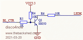 OK just double checked and this is what I found If you do BACKLIGHT command without the OPTION LCDPANEL ILI9341_16,RL loaded it responds as you say. 100 is OFF 0 is ON Once the OPTION LCDPANEL ILI9341_16 ,RL is loaded it responds as I expected. i.e. 0 is OFF , 100 is ON. I think you need to power off and then on after the OPTION is set so the driver is loaded. This makes sense as in the code is looks to see which LCDPANEL is in use to determine which way the backlight should work. If the display is not set it will go to 100-0. Regards Gerry Latest F4 Latest H7 FotS |
||||
| Andrew_G Guru Joined: 18/10/2016 Location: AustraliaPosts: 871 |
Hi Gerry, Thanks for hanging in there. I have: - the 32 pin version - OPTION LCDPANEL ILI9341_16,RL (I just did an OPTION LIST) - I've pressed the reset and unplugged the USB (several times) and it starts in dull/off mode - I have to do an OPTION BACKLIGHT x to see anything - if I redo OPTION LCDPANEL ILI9341_16 ,RL it complains "ERROR : Display already configured" - if I set OPTION AUTORUN ON when it starts the screen is blank but if stop it and I BACKLIGHT 50 (say) it was there all the time. - if in my program I have a BACKLIGHT x it works - BACKLIGHT 80 is dull, 20 bright { = Not what you would expect . . .} Figure that out . . . Is there any way of interrogating it as to what Backlight it is using? Cheers, Andrew |
||||
TassyJim Guru Joined: 07/08/2011 Location: AustraliaPosts: 6269 |
Using the latest beta: ARMmite MMBasic Version 5.07.00b8 Copyright 2011-2020 Geoff Graham Copyright 2016-2020 Peter Mather > option list OPTION LCDPANEL ILI9341_16, RLANDSCAPE OPTION TOUCH PB12, PC5 The system powers on with BACKLIGHT 100 which is fully OFF. BACKLIGHT 0 is full brightness I have not made any changes to the options. They are at the default settings. Jim VK7JH MMedit |
||||
| Andrew_G Guru Joined: 18/10/2016 Location: AustraliaPosts: 871 |
Jim, Thanks - that's two of us going mad? How do you get the following: (I sometimes see it but not always) Andrew Edited 2021-03-20 15:19 by Andrew_G |
||||
OA47 Guru Joined: 11/04/2012 Location: AustraliaPosts: 982 |
Reset switch rather than power cycle. OA47 |
||||
| disco4now Guru Joined: 18/12/2014 Location: AustraliaPosts: 1000 |
So have you both got the 32pin version? Mine is 40 pin with an adapter, this may be the difference? Can you see what these return. its ID1,2,3 as read from display. Maybe we can detect if they are different. ? HEX$(getscanline(1),2) ? HEX$(getscanline(2),2) ? HEX$(getscanline(3),2) Edited 2021-03-20 15:28 by disco4now Latest F4 Latest H7 FotS |
||||
| The Back Shed's forum code is written, and hosted, in Australia. | © JAQ Software 2025 |
