
|
|
Forum Index : Microcontroller and PC projects : MM+ as an mpg
| Author | Message | ||||
| motogeek Newbie Joined: 20/01/2021 Location: United StatesPosts: 5 |
I am trying to wrap my head around and application where I would like to use a 28 pin micromite to emulate an MPG signal. The typical MPG for CNC machines have a hand wheel that outputs A and B signals just like your typical encoder does. My thought is to use an analog joystick on two analog inputs (for x and y) and output a pulse stream on two pins (for the A and B signals) that are 90 degrees out of phase. The cnc requires a differential signal for A and B (A not and B not) which can be handled by a differential line driver no problem. Axis selection will be done in code to determine which axis will listen to the A and B signals etc.. but my big mental road block is how to create a pulse stream on one pin and have the second stream on the other pin be 90 degrees out of phase. Can this be done in code or would it be better to figure out some external hardware to make this happen? Thanks! EDIT: Both waveforms are 60% duty cycle Edited 2021-03-22 18:31 by motogeek |
||||
crez Senior Member Joined: 24/10/2012 Location: AustraliaPosts: 153 |
Another way of expressing the relationship of the two outputs of a quadrature signal that I think you are describing is If A goes high while B is low, step up. If B goes high while A is high, step up. If A goes low while B is high, step up. If B goes low while A is low, step up. the reverse of any of the above is a downward step state A B 0 0 0 1 1 0 2 1 1 3 0 1 stepping up from state 3 takes us back to state 0 stepping down from state 0 takes us back to state 3 |
||||
| motogeek Newbie Joined: 20/01/2021 Location: United StatesPosts: 5 |
Sorry... the duty cycle is 50% - not 60% |
||||
| Tinine Guru Joined: 30/03/2016 Location: United KingdomPosts: 1646 |
I think crez was pointing out that the phase offset shouldn't matter for what you are trying to achieve; all you need to do is switch states, accordingly. Furthermore, if you don't want to bother with the line driver, just feed the A & B. You shouldn't have to do anything with the complements. The following is a quad decoder that I wrote in another dialect of BASIC. This better illustrates the logic. The line labels indicate the current states: A1B1: If Chan_A = 0 Then Dec Counter Goto A0B1 Elseif Chan_B = 0 Then Inc Counter Goto A1B0 Endif Goto A1B1 A0B0: If Chan_A = 1 Then Dec Counter Goto A1B0 Elseif Chan_B = 1 Then Inc Counter Goto A0B1 Endif Goto A0B0 A1B0: If Chan_A = 0 Then Inc Counter Goto A0B0 Elseif Chan_B = 1 Then Dec Counter Goto A1B1 Endif Goto A1B0 A0B1: If Chan_A = 1 Then Inc Counter Goto A1B1 Elseif Chan_B = 0 Then Dec Counter Goto A0B0 Endif Goto A0B1 End Edit: Pay attention to the maximum frequency capability of the MPG input and delay your state-switching accordingly. Edited 2021-03-23 00:52 by Tinine |
||||
| Volhout Guru Joined: 05/03/2018 Location: NetherlandsPosts: 5927 |
Yes, it can be done in code. It is not even difficult to do (it is only a small program). crez gave you a good start with his truth table. You just step though that table upward, or downward, and achieve exactly what you need. You have to consider following however: 1/ you need to define the maximum speed and the minimum speed of change (when using an analog joystick you will most likely want to achieve controlled "single stepping", but also fast transfers to a new position. That needs to be tuned on the machine itself. 2/ You need to consider using a "lock / unlock" switch or button. The problem with an analog input is that (unless you make an expensive design, use expensive joystick) there may be offset that changes over temperature. That does not happen with an encoder, but could happen on an analog joystick. The switch will disable the joystick when not used. Below is a section of code that shows X direction (for X-Y you need to double this). And add the AD conversion and time delays and dead zone. they determine {condition_up} and {condition_down}. dim a(3) a(0)=&b00:a(1)=&b10:a(2)=&b11:a(3)=&b01 'chez his table i=0 'pointer in table setpin 24,dout 'A setpin 26,dout 'B do if condition_up then i=(i+1) and 3 elseif condition_down then i=(i-1) and 3 else 'do nothing endif pin(24)=(a(i) and 2) 'logical and to check if bit 1 is high pin(26)=(a(i) and 1) 'same for bit 0 pause 1000 '1 sec loop PicomiteVGA PETSCII ROBOTS |
||||
| Tinine Guru Joined: 30/03/2016 Location: United KingdomPosts: 1646 |
And/or establish a deadband for the joystick so that the axis doesn't drift when only the button is activated. Edit: @Volhout Ah, sorry, you already mentioned dead zone  Edited 2021-03-23 03:04 by Tinine |
||||
| vegipete Guru Joined: 29/01/2013 Location: CanadaPosts: 1179 |
Some clarifying is needed here. A joystick is a two axis device. An MPG is a single axis device. Do you want the MicroMite to send or to receive a single quadrature signal? My impression is you want the 'mite to SEND the signal, and you want the 'mite to read the joystick to determine exactly what to send. A picture always helps: (from the web) 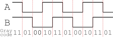 This shows us that the 2 pins outputting the signal have the repeating sequence of values 0,2,3,1 The PORT command is ideal to output this. DO PORT(<pinnum>,2) = 0 PAUSE 0.5 PORT(<pinnum>,2) = 2 PAUSE 0.5 PORT(<pinnum>,2) = 3 PAUSE 0.5 PORT(<pinnum>,2) = 1 PAUSE 0.49 LOOP This should output a quadrature signal on pins <pinnum> and <pinnum+1> at about 2 kHz. (I fudged the last pause command to account for loop overhead. YMMV) For the reverse direction, send 1,3,2,0. This should be checked with an oscilloscope to confirm the signal is clean and as expected. I would store the 4 values in an array, and step through the array. Also, a differential signal would easy to generate by extending this to 4 pins in a row and using the sequence 12,6,3,9. (Examine the binary representation to see where these come from.) Visit Vegipete's *Mite Library for cool programs. |
||||
| motogeek Newbie Joined: 20/01/2021 Location: United StatesPosts: 5 |
I just dug a bit and found that two jk flip flops can make this quite easy, so I can use the micromite to generate the pulse train I need on one pin and feed the two flip flops quite accurately. Thank you for the suggestions and safety considerations. I will have to think a bit about that safety thing for sure. |
||||
| Tinine Guru Joined: 30/03/2016 Location: United KingdomPosts: 1646 |
With all respect, you are over complicating this. Apart from the bonus of 4X resolution, the out-of-phase signals convey the direction (up/down) In your case, the direction is dictated by the user so all you need to do is output the bit pattern that will take you in the desired direction....no need to simulate an actual encoder and certainly no need for flip-flops. |
||||
| motogeek Newbie Joined: 20/01/2021 Location: United StatesPosts: 5 |
NOW I GET IT! Yes, just output the bit pattern. Onward to experimenting. Thank you for the help!!! |
||||
| Volhout Guru Joined: 05/03/2018 Location: NetherlandsPosts: 5927 |
I like the idea of having a joystick to control a CNC machine, but there is one thing to keep in mind doing this. The encoder has absolute positioning. Whenever you rotate the dial to a certain position, you end up at the same position on the CNC machine. A joystick has relative positioning. This is different. Compare a mouse (relative positioning) to the steering wheel of a car (absolute positioning). Try driving a car with a mouse. It is hard, and needs lot of practise. Anyway, I have tried to solve your puzzle. Here is the result tested on a breadboard. 'dual axis encoder simulator drive from 2 axis joystick 'IO pins used in PORT command AX=3: BX=4: AY=5: BY=6 SetPin AX,dout:SetPin BX,dout:SetPin AY,dout:SetPin BY,dout 'Analog input pins (0-3.3V) INX=26: INY=25 SetPin INX,ain:SetPin INY,ain 'Analog settings Centre = 3.3/2 Threshold = 0.1 'state table, both x and y use this table to convert count into state Dim S(3)=(&b00,&b10,&b11,&b01) 'start the heartbeat of the system (10ms tick) SetTick 10,DOINT 'set speed (at 10 x heartbeat = 100ms) maxX=10:maxY=10 'main loop Do 'a single PORT command ensures all pins change state simultaneous Port(AX,4)=S(x)+4*S(y) 'mesure joystick inputs IX=Pin(INX) IY=Pin(INY) 'IX=1.76 'IY=1.54 'calculate directions. When in centre+/- threshold 'updates to PORT may happen but no changes of port If IX>(Centre+Threshold) Then newX=(x+1) And 3 ElseIf IX<(Centre-Threshold) Then newX=(x-1) And 3 Else newX=x EndIf If IY>(Centre+Threshold) Then newY=(y+1) And 3 ElseIf IY<(Centre-Threshold) Then newY=(y-1) And 3 Else newY=y EndIf 'Calculate rate 'use a (1/x)^2 function to translate IX/IY to time 'at extremes (0V/3.3V) achieve 10ms (maxX/maxY=1), 'at threshold achieve 1 second (maxX/maxY=100) rX=Abs(IX-Centre)+0.01 'the 0.01 is added to preven divide by 0 rY=Abs(IY-Centre)+0.01 'rX/rY value range from value "Centre" to "0" maxX=Min((Centre/rX)^2,100) maxY=Min((Centre/rY)^2,100) 'Print newX,newY,rX,rY,maxX,maxY Loop 'this sub runs 2 software counters, for X and Y,when count runs out, 'a new update is done to the encoder outputs by copying variables. Sub DOINT cX=cX+1:cY=cY+1 If cX>maxX Then cX=0 'copy x=newX EndIf If cY>maxY Then cY=0 'copy y=newY EndIf End Sub You have 2 outputs for X (pin 3,4) and 2 outputs for Y (pin 5,6). Since I have no idea how fast your CNC is I drive these pins withe the PORT command (then all updates will happen at the same time). Your analog joystick has 2 potentiometers, connect these to pin 25 and 26 (or define others if you like). The potemtiometers must be connected between 3.3V and GND on the micromite. When you move the joysticks to the extremes you will get 100 encoder changes per second. When colse to centre it will be 1 change per second (allowing you to work precisely). There is a dead band (between +/- threshold) to ensure that when your joystick is a bit offcentre, the CNC won't change. All these values can be played with to match your user experience. One thing to take into account: the 28pin micromite output pins are 3.3V maximum. I am not sure what your CNC machine expects. You may need a buffer or level shifter, or even an optocoupler to stay on the safe side. I hope this works for you.... Volhout P.S. I am sure I can fit this in 10 lines also..... Edited 2021-03-23 18:32 by Volhout PicomiteVGA PETSCII ROBOTS |
||||
| The Back Shed's forum code is written, and hosted, in Australia. | © JAQ Software 2026 |
