Notice. New forum software under development. It's going to miss a few functions and look a bit ugly for a while, but I'm working on it full time now as the old forum was too unstable. Couple days, all good. If you notice any issues, please contact me.
Kamak Senior Member Joined: 13/04/2021 Location: CanadaPosts: 150
Posted: 05:39pm 16 Apr 2021
Copy link to clipboard
Print this post
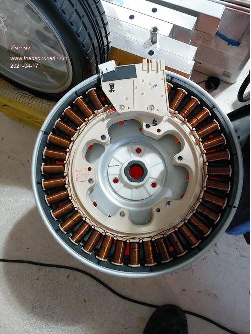
This is the start of a new build using a Samsung direct drive brushless permanent magnet DC motor as an AC induction generator utilizing the motor's inherent "back EMF" signal.
I am going to spec out and list this motor's stock mechanical and electrical parameters, to start with.
Motor design:
BLDC motor out of a Samsung Wf210anw washing machine https://issuu.com/heydownloads/docs/001___samsung_wf210anw_wf220anw_service_manual_rep
36 pole(coil) aluminum wound stator - 19ga (0.03589", 0.9116mm) wire, (unknown wrap count per pole as of the start of the build)
6.2 ohms resistance per total of the 12 pole coil count, for each of the three-phase legs. 30 wraps on the top layer of each pole.
Estimations of coil wraps per pole:
visibly 30 wraps on the top layer of each pole coils. Estimation of 5 layers = 150 wraps? Correction, it can not be an uneven number of layers of coil wraps, it must be multiples of 2, due to how the coils are constructed. They begin at, and end at the hub of each pole, hence multiples of 2 layers per completion. Therefore there must be either 4 layers or 6 layers.
19 ga aluminum wire has a 14.6-ohm resistance per 1000ft. The measured resistance is 6.2 therefore 6.2(1000)/14.6 = 424.65ft/leg, 424.65/12 poles = 35.38ft/pole approx. 35.38ft x 12 inch = 424.65 inch/pole coil, 424.65/150 wraps = 2.83 inch per wrap avg. Seems reasonable. Correction, 424.65/(30x4) = approx 3.5"/wrap, 424.65/(30x6) = approx 2.35"/wrap.
4 magnetic poles in each of 12 magnetic bricks (NSNS x 12 = 48 poles)
Magnetic flux density per magnet is approx 1750 - 1800 Gauss at their highest peak regions.
This stator will eventually be rewound with a specific gauge copper with a specific winding count, to be determined. I will soon be getting the stock generator's output voltage and current at a specific rpm, once I can dyno it on a bench test setup. I will then strip the stator of its aluminum wire and start experimenting with winding counts and wire gauge sizes.
Edited 2021-04-18 01:28 by Kamak
get real Newbie Joined: 16/12/2020 Location: United StatesPosts: 9
Posted: 03:36pm 17 Apr 2021
Copy link to clipboard
Print this post
Cant wait to see how this turns out. I stripped the wire off one and rewound it back on. I did 8 strips 75ft long twisted together then wound it back on. Then hooked a 48v e-bike controller to run it. Then I coupled 2 more motors on rewired to 4x3c. Now I'm trying to use a ballast transformer to get 48v dc through a bridge rectifier to run the e-bike controller. Not sure what the amp draw on transformer is yet. Trying to incorporate this in my solar system to help run a/c and charge batteries at same time. I am at the point of wiring transformer in.
Kamak Senior Member Joined: 13/04/2021 Location: CanadaPosts: 150
Posted: 03:52pm 17 Apr 2021
Copy link to clipboard
Print this post
Off one? Off just one of the poles?
75ft isn't a lot of wire. What gauge wire was it? or the dia of the wire?
8 strips? I assume you mean strips = layers?
How many wraps did you get per layer? Did you count the total number of wraps?
Just a single pole from any of these types of BLDC motors should yield approx 100 - 200 wraps/pole and approx 40ft. But you said 75ft and 8 strips so that must have been fairly thin wire
Did you do any tests to compare volts and amps per rpm?
Kamak Senior Member Joined: 13/04/2021 Location: CanadaPosts: 150
Posted: 08:57pm 18 Apr 2021
Copy link to clipboard
Print this post
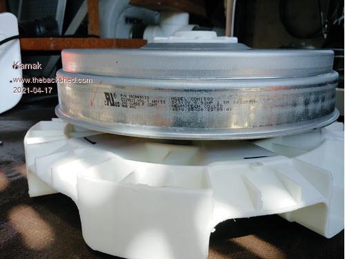
Stock Samsung P/N: 09CA49132 Stator
900mm ID. Mag ring 75mm W x 35mm L x 5mm Thk mag bricks 12 mag bricks 4 poles per mag brick NSNS 75mm/4 = 18.75mm W magnets 35mm L x 18.75mm W x 5mm Thk per mag pole 48 magnets @ 7.5deg of arc per magnet, 15deg arc per "like" polarity Stock maximum mag flux density = approx 1750/1800 Gauss (at the centerline)
36 coil poles = 360deg/36 = 10deg arc per coil pole 3 phase winding XYZ = 30deg arc per "common" phase winding
15deg of arc per mag pole(centerline) of "like" magnet polarity 3.75deg+ 7.5deg +3.75deg N | S | N = 15deg C|C N|S|N|S @ 30deg of arc per mag brick 30deg per "common" phase winding therefore the "like" magnetic pole polarities (and transitions thereof) will always aline with the "common" coil windings throughout rotation, as 15deg is an even common denominator of 30deg. Edited 2021-04-19 08:43 by Kamak
get real Newbie Joined: 16/12/2020 Location: United StatesPosts: 9
Posted: 10:50pm 18 Apr 2021
Copy link to clipboard
Print this post
I TOOK ALL THE WIRE OFF A 36 pole stator. I measured out 75ft and folded the wire over 8 times. Which would be 75x8=600ft. Twisted the 8 strands and wired one phase then did the other 2 phases the same. Not sure of how many twisted on each pole but I filled them all the same. Somewhere near 2000ft or more in wire on whole stator. It works great with the E-bike controller turning 2 more of the same motors in 3x4c. Not getting the amps I hope for so thinking about putting CAP Doublers in and using a transformer for the 48v dc to run e-bike controller.
Kamak Senior Member Joined: 13/04/2021 Location: CanadaPosts: 150
Posted: 11:48pm 18 Apr 2021
Copy link to clipboard
Print this post
You wound the poles, each, with twisted 8 strand enamel wire? Like twisted multi-strand wire, you would find in a poly-coated, multi-stranded wire/cable? Or you only twisted the end( together) of the 8 wires, and left the rest of the wires straight/in parallel with each other as you wound them around each pole?
Did you cut the wire where you folded it? Edited 2021-04-19 09:53 by Kamak
Kamak Senior Member Joined: 13/04/2021 Location: CanadaPosts: 150
Posted: 11:59pm 18 Apr 2021
Copy link to clipboard
Print this post
If you didn't cut the wire, you would end up with 4 wires with electrical polarity going CW and 4 wires with electrical polarity going CCW, over the entire core/pole. This would create a near-net-zero output. If you twisted the 8 wires together before winding the core, this too would reduce EMF within the wire.
I'm just confused about why you said folded and twisted. lol
Is there not just one continuous wire wound around each core pole and then all "Like" phase poles together as one?
It sounds like you wound 8 folded lengths of the same wire around each phase array cores, to save on time.
"I measured out 75ft and folded the wire over 8 times. Which would be 75x8=600f"
Or did you mean, you measured out 75ft at a time and folded over (wound) 8 layers around each pole, which equals 600ft per core pole? This seems to make sense as a small gauge wire would be realistically approx 600ft per pole
Your original post read " I did 8 strips 75ft long twisted together then wound it back on."
So I'm really not sure how to envision this in my head. Folded and twisted could mean you turned 8 parallel wires into a 75ft long w/ larger dia single multi-stranded twisted wire, then wound it around the poles. Edited 2021-04-20 00:48 by Kamak
Kamak Senior Member Joined: 13/04/2021 Location: CanadaPosts: 150
Posted: 03:19pm 19 Apr 2021
Copy link to clipboard
Print this post
Stock Samsung P/N: 09CA49132 Stator
900mm Inner Circumferance. Mag ring 75mm W x 35mm L x 5mm Thk mag bricks = 30deg of arc
12 mag bricks = 360deg of arc 4 poles per mag brick NSNS = 30deg of arc 75mm/4 = 18.75mm W magnets = 7.5deg of arc 35mm L x 18.75mm W x 5mm Thk per mag pole 48 magnets @ 7.5deg of arc per magnet, 15deg arc per "like" polarity Stock maximum mag flux density = approx 1750/1800 Gauss (at the centerline)
36 coil poles = 360deg/36 = 10deg arc per coil pole 3 phase winding XYZ = 30deg arc per "common" phase winding
15deg of arc per mag pole(centerline) of "like" magnet polarity 3.75deg+ 7.5deg +3.75deg N | S | N = 15deg C|C N|S|N|S @ 30deg of arc per mag brick 30deg per "common" phase winding therefore the "like" magnetic pole polarities (and transitions thereof) will always aline with the "common" coil windings throughout rotation, as 15deg is an even common denominator of 30deg.
Kamak Senior Member Joined: 13/04/2021 Location: CanadaPosts: 150
Posted: 09:15pm 19 Apr 2021
Copy link to clipboard
Print this post
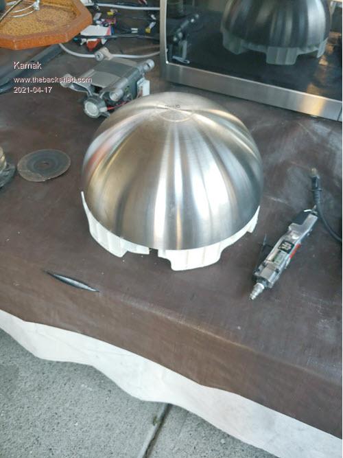
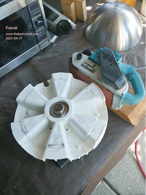
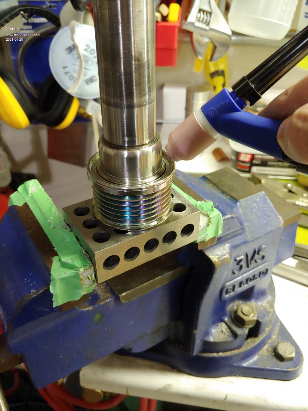
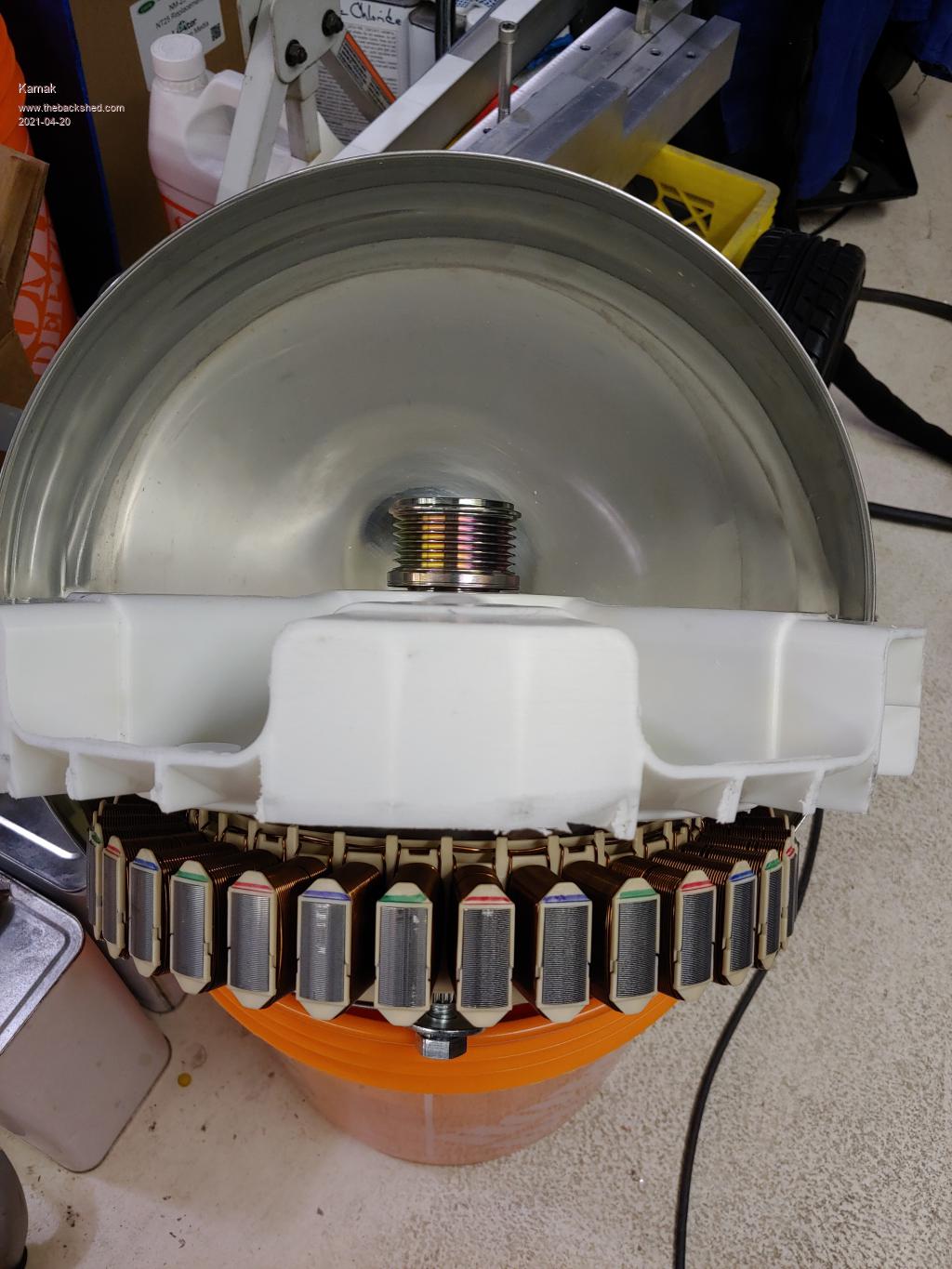
Temporarily Welded on a pully for bench testing.
Kamak Senior Member Joined: 13/04/2021 Location: CanadaPosts: 150
Posted: 12:00am 20 Apr 2021
Copy link to clipboard
Print this post
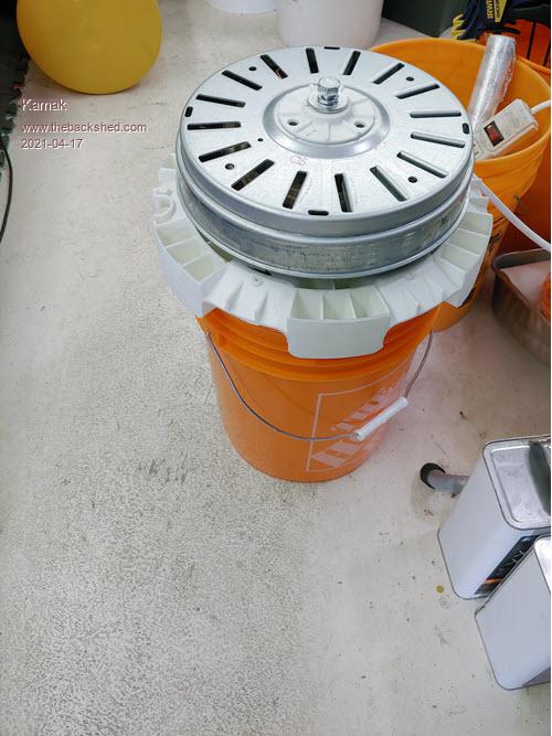
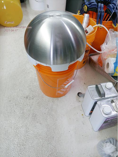
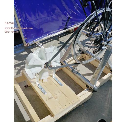
The Test Bed
Edited 2021-04-20 10:03 by Kamak
Kamak Senior Member Joined: 13/04/2021 Location: CanadaPosts: 150
Posted: 12:03am 20 Apr 2021
Copy link to clipboard
Print this post
The Test Bed
Kamak Senior Member Joined: 13/04/2021 Location: CanadaPosts: 150
Posted: 02:38am 20 Apr 2021
Copy link to clipboard
Print this post
I got 1Kv out of it. lol
Kamak Senior Member Joined: 13/04/2021 Location: CanadaPosts: 150
Posted: 02:42am 20 Apr 2021
Copy link to clipboard
Print this post
So....the BEMF AC frequency? How to calculate this?
Is the AC freq a multiple of the rpm x the number of N|S magnetic pairs? ie, the N|S pair makes a full cycle AC signal.
Ex. If the rotor is rotating at 1 RPM and there are 24 N|S pairs in the rotor, then the AC signal freq is 1 x 24 = 24Hz?
Technophiliac Regular Member Joined: 18/12/2020 Location: New ZealandPosts: 89
Posted: 03:13am 20 Apr 2021
Copy link to clipboard
Print this post
Hey dude, your prolific publication rate is interesting and certainly I would not want to see you discouraged. If it were me I would be trying an oscilloscope or multi-meter with frequency measure to look to answer your question.Davo, Wellington. You can have it perfect, on time, and at the best price. Choose any two.
Kamak Senior Member Joined: 13/04/2021 Location: CanadaPosts: 150
Posted: 03:28am 20 Apr 2021
Copy link to clipboard
Print this post
Yeah, that would be nice, but that's an expense I don't want at the moment. But sure wish I had one, like years ago now.
I have a Digital Tachometer, I have the hall sensor from the motor, so I can at least get a redundant reading of RPM. My handheld DMM can only read up to 200Hz.
From my calculation, a rotor at 100 RPM would produce an AC signal of 2400Hz. Someone correct me if I'm wrong.
There are 24 N|S pairs in this rotor, then the AC signal freq is X rpm x 24 Edited 2021-04-20 13:31 by Kamak
Kamak Senior Member Joined: 13/04/2021 Location: CanadaPosts: 150
Posted: 03:51am 20 Apr 2021
Copy link to clipboard
Print this post
So my bike rim/pully is 565mm OD. the rotor pully is 49.73mm
565/49.73 = 11.36:1 Ratio
100rpm rotor = 100/11.36 = 8.80rpm Bike pully.
Depending on the gear ratio of the bike, I might be able to turn the crankshaft with a variable speed drill, to get accurate steady rpm, if the torque isn't too high.
Butcher Newbie Joined: 03/04/2021 Location: New ZealandPosts: 7
Posted: 06:41am 20 Apr 2021
Copy link to clipboard
Print this post
I have a 36 pole F&P (factory de-cogged) stator that had Alluminium wire on it. I unwound the al wire and placed into my scrap bin. I am winding 0.8mm Copper wire onto it (same number of turns).
I estimate that it will take me about 9 1/2 hours to do so! I have done about 10 poles already. It takes me about 15 mins per pole on average (sigh).
Point is, you may want to stick with Alluminium !
Soldering to Alluminium is difficult and it can be unreliable etc.
You could simply unwind one pole and count no. of turns and then rewind...
Be careful. Anything over 50V can be lethal. I am not joking. I am talking 50V peak to peak, not RMS either.
Thicker wire = more voltage due to less ohmic losses (less resistance) thus greater efficiency.Testing, testing, ...1 ...2 ...3
InPhase Senior Member Joined: 15/12/2020 Location: United StatesPosts: 178
Posted: 12:52pm 20 Apr 2021
Copy link to clipboard
Print this post
No, because RPM is minutes and Hz is seconds. (RPM/60) x N = Hz, where N is the number of pole pairs. Edited 2021-04-20 22:52 by InPhase
Kamak Senior Member Joined: 13/04/2021 Location: CanadaPosts: 150
Posted: 03:19pm 20 Apr 2021
Copy link to clipboard
Print this post
hehe, yup, came here to correct myself, and you beat me to it.
My DMM can measure up to 200hz, and I hit 200hz quite early in the spin-up
24 pole pairs per 360deg rev.
So if 2400cpm (cycles per minute) is at 100 rpm that would = 2400/60 = 40Hz at 100rpm, This makes sense with measurements.
200hz would be at 500rpm 500rpm is quite easy to hit with the pully ratio I have with is 11.36:1 500rpm of the rotor would = 500/11.36 = 44rpm of the large pully. This does seem to jive. I really need to get a tachometer working and a steady state rpm.
Kamak Senior Member Joined: 13/04/2021 Location: CanadaPosts: 150
Posted: 03:25pm 20 Apr 2021
Copy link to clipboard
Print this post
I'm a TIG welder so I could tig the aluminum together quire easily.
But no, I am going to rewire it and change out the magnets also.
As for the voltage, I'm comfortable working with high voltages. I've worked as a millwright for many years.
I'm seriously considering maintaining a 240V AC min. out of the rotor for long runs with minimal voltage loss, to a transformer. running long runs of wire at 12v/24v/even 48v is not a good idea.