
|
|
Forum Index : Other Stuff : Sizing Pelton wheel for F&P?
| Page 1 of 2 |
|||||
| Author | Message | ||||
| flyingfishfinger Senior Member Joined: 12/09/2020 Location: United StatesPosts: 102 |
Hi all- Just getting started here with micro hydro & trying to understand what I need. I have an F&P machine I'd like to use, but I'm unsure how to size the Pelton wheel needed. Is there something specific I should use for the F&P type generators, or does it need to be matched to my head & flow? Thanks, Rafael |
||||
| Warpspeed Guru Joined: 09/08/2007 Location: AustraliaPosts: 4406 |
I am not a hydro guy, but I suppose the first thing might be to arrange a suitable tapered water nozzle to suit your head and flow. As only one bucket at a time will be driven, it should be possible to measure the tangential force generated against a single suitably sized bucket. A lever arm and spring balance should be pretty easy to rig up. That would be the fully stalled rotor torque, running torque will be less, possibly about half that. If you can also measure the water velocity issuing from the nozzle, that might give you a clue to the available drive power available, and from that you can work out the required wheel diameter depending on the most useful rpm and torque ranges. The F&P can be connected in many different ways to generate different voltages and currents at various rpm. Some experimentation there might be useful too. In the end, there are probably many different combinations that should work pretty well, its just a case of testing and experimenting and making improvements gained from experience. Cheers, ĀTony. |
||||
| Davo99 Guru Joined: 03/06/2019 Location: AustraliaPosts: 1577 |
I think Tony hit on the important first question, what's your Flow and head? I think you need to design for that first and foremost because in most cases I have read about, water supply is the limiting factor in most setups. If that's not a problem, there should be plenty of tables you can find to give you an idea. I know of a couple of companies that do a lot with the F&P units here and in NZ but not in the states although I'm sure there would be a few at least. |
||||
| flyingfishfinger Senior Member Joined: 12/09/2020 Location: United StatesPosts: 102 |
Ah, fair. Thanks for the info, I'm still working on good measurements for flow & head, but ROUGH estimates put it around 10L / sec and possibly up to 30m head if I make my pipe long enough. Based on this page (https://www.canyonhydro.com/guide/HydroGuide12.html ) with these numbers and assuming 50% efficiency, I should be able to get a little over ~ 1kW of power. The other issue I have is that my stream is quite far away from my living (& battery) setup(500-800m). If I rewire the F&P for good output at 12V, I will have terrible line losses. So this begs another question: An UNMODIFIED F&P puts out quite a high voltage - can I just transmit that with more reasonable wiring & step it down at the other end before feeding a charge congroller? I'm not sure how I would efficiently go about doing that. Transformer + rectifier? R Edited 2021-04-30 04:04 by flyingfishfinger |
||||
| mab1 Senior Member Joined: 10/02/2015 Location: United KingdomPosts: 149 |
As it's a PMG and you're probably going to have to down-convert the output after transmission I'd say the exact size of wheel won't be critical. The optimum speed of the wheel is such that the velocity of the spoon is about 1/2 the velocity of the water jet hitting it. I can't recall quite how you calculate the jet velocity but obviously it depends primarily on the available head. Wheel size only becomes critical if you're hoping to use the genny power directly and need it to generate at 50/60Hz at line voltage to suit the loads. I found Joe at H-Hydro.com very helpful and seem to remember he has some spreadsheets for calculating jet velocities and (turgo) wheel diameters to achieve an optimum RPM for a generator. If you're in the US you might consider one of his turgo runners - they're much the same efficiency as a pelton and in my experience are less critical of jet alignment. Checkout the powerspout advanced calculators as they're very handy for determining optimum pipe sizes and available power. For long range transmission i'd definitely go for higher voltage; tranformer and rectifier to battery is certainly workable and at low powers is often the best way. If you're going up to ~1kw it may be better to go: HV genny -> transmission line -> rectifier -> grid-tie inverter -> primary inverter -> battery (or GTI -> grid if you have the grid-connected option). some GTI's will take up to 700v d.c. - possibly more - and come with a MPPT function so automatically find the best load for the turbine/genny/transmission line combo. This also has the advantage of just one voltage conversion between the genny and the A.C. load that's using the power. I use a pelton and a turgo and both transformer and GTI methods; if there's not much water (like now) i use a transformer and (Ideal LT4320 based) rectifier to battery. When It was running 450w during the winter i had it running ~360v a.c. along my 120m transmission line to a rectifier and an SMA sunny boy 1200 solar GTI. I do have a 'safety net' transformer/rectifier setup in parallel with the GTI in case the GTI trips out, otherwise the unloaded generator output rises above the max GTI input voltage. |
||||
| flyingfishfinger Senior Member Joined: 12/09/2020 Location: United StatesPosts: 102 |
Oh, those calculators are nice. With the numbers I have, I seem to arrive similar numbers whatever way I calculate it, between 1 & 1.5 kW. BUT using the Powerspout calculators, the optimal RPM appears to be around 900RPM...which seems way too high for an F&P (the charts top out at 500RPM, and H-Hydro's charts are MUCH higher (~ 2000 RPM). What's the max power I can safely get out of an F&P? None of the charts show F&P RPM for a NON-rewired configuration, so I'm not sure how to approach this. For the transmission issue, we don't plan on feeding a grid, there isn't one anywhere nearby. I currently have a 12V system running off a few small PV panels through a Victron BlueSolar controller, so I'd like to charge the same batteries (and also dump load to a water heater). R Edited 2021-04-30 08:54 by flyingfishfinger |
||||
| Warpspeed Guru Joined: 09/08/2007 Location: AustraliaPosts: 4406 |
Current will be limited by heating in the wire, and rpm by mechanical considerations. So the starting point might be an unmodified F&P running at an rpm where the ac output voltage is perhaps somewhere around 200v to 300v. Feed the three phase ac back to your home with three wires at that full voltage. You can then step that down to any required ac voltage with either a three phase transformer or three individual transformers. Rectify that into low voltage dc and that is all you really need. The current in the cable might be 500 watts per phase, or perhaps a couple of amps. Cable losses should be minimal. Give some thought to the possibility of running bare overhead wires between very high poles. Steel fencing wire is ultra cheap and very strong. Its more work initially to put up, but ultimately safer and should be far more reliable in the long term. The only thing that can really go wrong is a wire comes down. That should be pretty easy to spot and to fix. Cables running directly over the ground will eventually fail for many varied reasons, and it can sometimes be difficult to locate the exact point of failure in a long run. Cheers, ĀTony. |
||||
| mab1 Senior Member Joined: 10/02/2015 Location: United KingdomPosts: 149 |
I don't know anything about the F&P motors alas so I cannot advise on them (although, I thought the powerspout were based on something like it). In theory, if you can determine what rpm is optimal for your F&P then you can get/make a pelton (or turgo) wheel to suit:- i.e. if you double the diameter of the pelton wheel then the optimal rpm will be half. So if you can determine your jet velocity from your 30m head, then 1/2 of that gives you the best spoon velocity (linear velocity), then work out what circumference of pelton wheel will give you the rpm that your F&P needs to work best. Not quite so easy in practice as theory of course, but as long as your in the ball-park you should be OK. charging batteries and dumping into a water heater is fine, although if you're going up to 1kw or even 1.5kw then it may be worth considering a 24v or 48v system: 1.5kw at 12v gets very cumbersome. |
||||
| flyingfishfinger Senior Member Joined: 12/09/2020 Location: United StatesPosts: 102 |
Cool, just wanted confirmation that this makes sense. I'm guessing I can then feed the result into an MPPT / charge controller normally. For the wheel diameter stuff - are you assuming a constant load? Otherwise the RPM will change either way for a given nozzle velocity. I'm still unsure what the "optimal" RPM for an UNMODIFIED F&P is, the page about it only gives ranges for various types of rewiring. Yes, we might move to a 24V system. Right now my inverter is 12V input only though, so I'll keep that until we upsize our whole site. I was thinking if the charge controller has a proper status output, I should be able to switch the HV AC from the generator into a water heater directly. That's less 12V, high current wiring. Thanks for the advice so far, this is a good start (I think). Cheers, R Edited 2021-05-01 09:45 by flyingfishfinger |
||||
| zeitfest Guru Joined: 31/07/2019 Location: AustraliaPosts: 375 |
The Rainbow Power Company (rpc.com.au) originally had microhydro expertise (spreadsheets etc), don't know what they are like now though. Maybe worth a try. They started in the beginnings of the alternative power movement, way before rainbows were appropriated as political symbols. IIRC there was an identity nicknamed "Peter Pedals" and a pelton wheel made from recycled cutlery (!). Good luck ! |
||||
| Warpspeed Guru Joined: 09/08/2007 Location: AustraliaPosts: 4406 |
I don't really know either, but it should be fairly easy enough to find out. Just spin it up with a cordless drill without any load, and measure the voltage. The unloaded voltage will be exactly proportional to rpm, so you only need one measurement point to figure that part out. If you do not already own one, I suggest you buy one of those e-bay digital tachometers, they are not that expensive and would be very useful for this type of project. Rpm can be measured either by direct physical contact with a rubber bung, or optically with a piece of shiny reflective tape stuck onto a rotating part. The F&P voltage will fall slightly under electrical load, but not by a lot. It will at least give you a ball park figure for rpm in the voltage range you might be aiming for. If you can spin something up in the issuing water jet, your tachometer should be able to read that also, and you can then calculate the free flow water velocity. Cheers, ĀTony. |
||||
Revlac Guru Joined: 31/12/2016 Location: AustraliaPosts: 961 |
Yes RPC did quite abit of this sort of stuff, I did get to see one of the hydro power, pelton wheels in Acton, at a place, I think it is now called Adjinbilly Rainforest Retreat, Kim Best was there at the time and showed us the system working. The pelton wheel was not large diameter but it had spoon shaped, and the water nozzles where aimed at the centre of the spoons around the wheel, I think it had 4 nozzles driving it? and some sort of Governor, Iris or something to control the flow it needed. The rest of the magic was in the control box under one of the 3 cabins did see some 4wd batteries under the cabins, all cabins were powered and this system kept power up to all of them. Found some Info here Cheers Aaron Off The Grid |
||||
| mab1 Senior Member Joined: 10/02/2015 Location: United KingdomPosts: 149 |
No, I'm not talking about constant load - at this point you're trying to find out what size wheel will drive your F&P at the about the right rpm:- so you need to either find out what the right RPM will be, if someone can tell you, or do what Warpspeed says and work it out yourself; then with that RPM figure in mind you can determine what size of pelton wheel will, under load, turn at about that RPM, In practice, yes, the RPM will change away from optimal if the load changes - so ideally the load on the generator should be sort of constant, as the power coming through the water jet is constant. That's the advantage of using an MPPT controller on the output of your generator as it will find the optimum load, at the optimum RPM even if it isn't exactly the RPM you estimated it would be at the design stage - as long as you were in the right ball-park. You can use transformers/rectifiers to battery of course (as i am right now) but as the battery voltage rises the RPM of the generator will rise too - in theory this could be used as as a self regulating feature:- if the RPM rise above optimal as the battery voltage rises then the power coming into the battery will fall off, reducing the amount that needs to be dumped; similarly if the load on the battery pulls the voltage down, then the power from the genny rises as the RPM approach optimal again. In reality I find the Power vs loading curve for hydro is very broad - much more so than for solar panels - so once you've found the optimum loading, small variations in RPM caused by battery voltage don't make a noticeable difference. Edited 2021-05-02 06:30 by mab1 |
||||
| Warpspeed Guru Joined: 09/08/2007 Location: AustraliaPosts: 4406 |
What I understand happens, is that with zero electrical load, your pelton wheel will spin as fast as the water comes out of the jet. That will also create a very high open circuit voltage proportional to the actual rpm. As you apply more electrical load the pelton wheel will slow down as power is actually transferred into the generator. The voltage falls in proportion to the reduction in rpm, and also because of the electrical resistance of the windings in the generator. That will be fairly minor, the main drop off in voltage will be from reduced rpm under load. If you keep increasing the electrical load, the voltage and rpm will both fall to roughly about half the open circuit voltage, and you will measure a maximum electrical power output at that point. If even more load is applied, the rpm will drop off even further, but the fall in voltage will be more than the current increases, and electrical power will fall below the peak. So the idea is to design everything so that the actual final operating voltage and rpm is in the region of half the zero load voltage and rpm, and there you will find the maximum power output. An MPPT system will seek and find that point, but that assumes the system is designed correctly in the first place, and there is sufficient load for the MPPT system to work with. Cheers, ĀTony. |
||||
| Revlac Guru Joined: 31/12/2016 Location: AustraliaPosts: 961 |
Found a great deal of information at flowtrack somehow Didn't see the link earlier.  Cheers Aaron Off The Grid |
||||
| flyingfishfinger Senior Member Joined: 12/09/2020 Location: United StatesPosts: 102 |
Right, got some more information. I appear to have a 42-pole 60s F&P, and did the drill test to find open-circuit voltages: 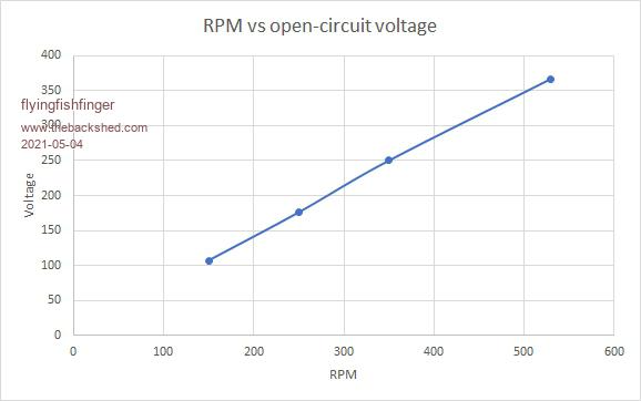 I'm guessing keeping the RPM lower will be better for bearing lifetime - but otherwise I'm still unsure how to pick a target. I feel like I'm missing something fundamental here, though. There are too many variables that I'm not sure how to eliminate properly. For example, if I pick 500RPM and a 20cm diameter Pelton wheel ($50 on Ebay), that's 10m/sec on my jet velocity. But, if at max power the RPM is cut in ~ half, do I size the jet velocity for that instead? ...I have too many questions, sorry. Newbie here  R Edited 2021-05-04 11:40 by flyingfishfinger |
||||
| Davo99 Guru Joined: 03/06/2019 Location: AustraliaPosts: 1577 |
Been a dream of Mine for a long time to have a property with running water to set up a MH system. To see on The RPC site the statement " Due to the many significant advantages of solar power, Rainbow Power Company no longer supplies or services hydro power systems. Solar panels are cheap, there are no moving parts, maintenance is generally not required, and qualified installers are abundantly available" is bit of a wake up call. MH seems like more fun but then again, that may grow old real quick. Panels certainly easy and straightforward as well as reliable.... which makes them kinda boring to me as well. I always sort of pictured my dream bush block having lots of trees and despite having so much solar now in rural Suburbia, never really saw that as something I'd have a lot of off grid. I would want the bush well back from the house so no reason I couldn't have it I suppose. Always hoped for good running water to have Hydro power 24/7. Might be for the best this is never likely to eventuate with my misguided concepts. :0) |
||||
| Warpspeed Guru Joined: 09/08/2007 Location: AustraliaPosts: 4406 |
If you use proper ball bearings, they should last forever if you can keep the water and grit out. Suppose you measure your nozzle flow velocity, and find a suitable turbine wheel that spins at 500 rpm unloaded (for example). Fully loaded it will be slowed down to about 250 rpm and perhaps a theoretical 170 volts. It will be less than that under electrical load, possibly about ten percent less when used as a generator. So let's assume 150 volts rms phase to phase under load for this example. Now if you are charging a 12v battery to about 14.3 volts with an MPPT controller, the controller will need some extra dc voltage to work from. Probably about 18v to 20v perhaps. That is when its all working properly under load. If you disconnect the load, the voltage from the F&P might immediately double as the turbine speed doubles. And you might easily see 36v to 40v (or more) at the MPPT controller input. That might sound ridiculously high for a 12v system, but it would actually be about right, and what you need to do the job. For this example only, you might need a transformer and rectifier to drop 350v (at 500 rpm) down to 40v dc under no load, or 150v (at 250 rpm) down to 18v to 20v dc t full load. Cheers, ĀTony. |
||||
| flyingfishfinger Senior Member Joined: 12/09/2020 Location: United StatesPosts: 102 |
Ah, you guys replied while I was adding the bit about the jet velocity to the chart. But ok, this is very useful. (Aside, it's hard to "experiment" on site - our property is ~ 8 hours away from where I live, and 2 hrs to the nearest hardware store. So I & bring whatever I need for one trip, and if something doesn't match I'll have to wait a month or two until the next trip. Hence I'm trying to plan and understand as much as possible beforehand) R Edited 2021-05-04 11:47 by flyingfishfinger |
||||
| Warpspeed Guru Joined: 09/08/2007 Location: AustraliaPosts: 4406 |
Its not too bad. Once you have some basic test data to work with from both the nozzle velocity and F&P rpm/voltage characteristic, you can then select a suitable turbine wheel diamater from what is commercially available. Its then a case of some further testing of the running turbine to find the maximum power point which should coincide with about half the unloaded wheel rpm. Whatever voltage and current you end up with from the F&P can then be matched to the input requirements of your MPPT controller with a suitable transformer ratio. Its all pretty straightforward engineering. Cheers, ĀTony. |
||||
| Page 1 of 2 |
|||||
