
|
|
Forum Index : Electronics : Bruce Inverter build
| Author | Message | ||||
Revlac Guru Joined: 31/12/2016 Location: AustraliaPosts: 961 |
Now with 12 turns, I can see how it adds up, quite dramatic.  The little LC meter, Calibrated it each time as usual, tested with 12 turns and returned a reading of 74uH or something, so re-calibrated and tested 2 more times and got the desired result, apparently a wire contacting a finger will stuff up the readings, so best to check if not sure.  The air gaps are the same, I think the edge of the spacers are a little frayed. 94uH @ 391568Hz Close enough to the 97uH would be some error margin with these meters. 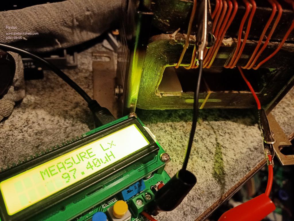 Cheers Aaron Off The Grid |
||||
| Warpspeed Guru Joined: 09/08/2007 Location: AustraliaPosts: 4406 |
There can be problems measuring any inductor, as it always has to be done with ac at some particular measurement frequency. Now any inductor will also have inherent stray self capacitance, and hence a self resonant frequency. Things can go really screwy around the self resonance point, or even close to it. Errors can be huge and the results meaningless. So don't be too surprised if three different types of measurement instruments produce three different inductance values. Try to fit on as many turns as you can possibly squeeze in there, using the thinnest wire you dare use at full maximum current. That will give you the greatest combined inductance and saturation figures. Then tweak the air gaps trading off inductance against final saturation. Cheers, �Tony. |
||||
renewableMark Guru Joined: 09/12/2017 Location: AustraliaPosts: 1678 |
That's the same meter I have, they measure a odd way which gives a consistent, but much lower reading. From memory you can't change the frequency. Have a look here https://www.thebackshed.com/forum/ViewTopic.php?TID=12027&P=33 Bottom of the page. Cheers Caveman Mark Off grid eastern Melb |
||||
| Revlac Guru Joined: 31/12/2016 Location: AustraliaPosts: 961 |
Some time back I tried a large choke from an old battery charger, heavy wire, large air gap, lots of turns etc, checked it with this meter and it was 685uH and produced the nastiest waveform ever seen and high idle current, under light load it got much worse, just my findings on a previous build, results for others may differ. Think I will stick with the sweet spot with this one, and wind it up with a jig on the lathe, did one by hand......fun it was not. They are helpful for this even if not perfect, have tested a few capacitors as well, been very handy for the price .You have reminded me of another project that needs to be finished, the little Charge controller, most of it is done and will post one day.  Edited 2021-09-07 21:41 by Revlac Cheers Aaron Off The Grid |
||||
| Warpspeed Guru Joined: 09/08/2007 Location: AustraliaPosts: 4406 |
I would expect to see a horrible wobbly distorted waveform under no load, exactly as you describe. The reason being the high series impedance of the choke decouples the transformer from the PWM waveform, which is what the choke is supposed to do. The greater the inductance the more free the transformer is to "do its own thing". The transformer will have a natural resonance of typically a few hundred Hz, and that can be excited into ringing from a harmonic of 50Hz. These wobbles will be stationary because they are a direct harmonic multiple of 50Hz. The resonant wobble below looks to be at about the tenth harmonic, probably 500Hz. This is bad enough, but it can be a lot worse than this if its a lower harmonic. 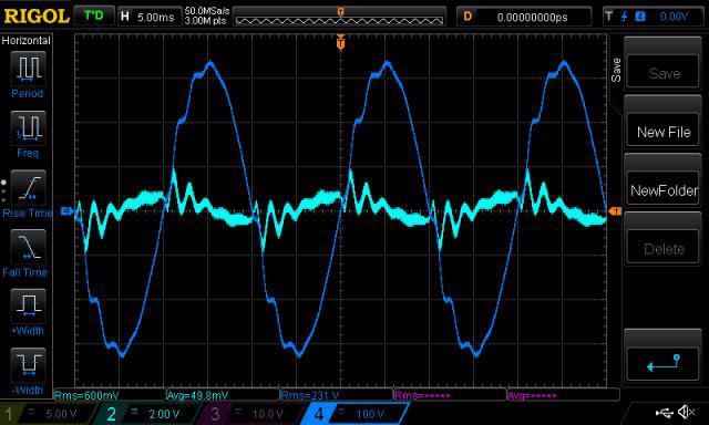 People see this and realise its being caused by the choke, which it is, and think the choke is crap. That is entirely the wrong conclusion. A good high inductance choke offers many benefits, but also creates an interesting new problem. If you add capacitance across the transformer secondary, this obviously lowers the transformer resonant frequency. All that does is make the wobbles larger, as it now resonates at a lower harmonic where there is even greater energy to cause the wobbles. But there is a trick !! If you move the resonant frequency down to EXACTLY 1.5 times the inverter frequency (75Hz for 50Hz inverter) any slight resonant buildup of energy in one cycle ends up being out of phase and cancelled by the following cycle. Its a kind of automatic self damping effect, and its very effective in reducing wobbles to the point where they are no longer visible. This tuning process needs to be pretty precise to be effective, maybe 75Hz +/-1Hz works very well. Just experimenting with a whole bunch of random capacitors will only make it worse. The tuning process must be very deliberate and precise set to an accurate frequency. The wobbles are a resonance, which is worst at zero load, or light load. Under heavy inverter load, the wobbles will be somewhat damped out by the load. Very severe wobbles will definitely increase idling current, because the resonant buildup of energy in the transformer is fighting the inverter. Once the transformer is properly tuned, idle power will drop, you will have a clean sine wave, and all will be well. Edited 2021-09-08 03:08 by Warpspeed Cheers, �Tony. |
||||
| brucedownunder2 Guru Joined: 14/09/2005 Location: AustraliaPosts: 1548 |
I have fitted the shelf on brackets, plenty of room for choke and other parts . the coil goes bottom left ,choke on top . Had a bit of grief posting the pic ,must be something astray with my I-pad or me ,we'll blame me !. I'm a bit slow at working on this inverter, many other pressing things to fix around the house. Frig carked it, water seeped through to my solar racks,, washing machine decided to rattle and Hum !, hot water system wanted a new heater installed, and ,of course, I still have my concrete water tank to tape-up the cracks, before the rain comes. So, you can imagine ,with all these hobbies AND me going to hospital visit every week on and off ,not much time left. But, I'm feeling fine this last year , so the dreaded "C" is taking a rest... Bruce 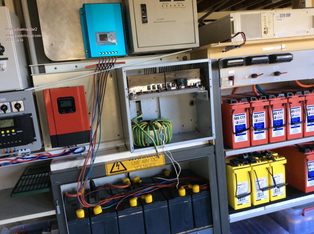 Edited 2021-09-14 11:41 by brucedownunder2 Bushboy |
||||
| Revlac Guru Joined: 31/12/2016 Location: AustraliaPosts: 961 |
That looks better Bruce, I hadn't thought about using angle there, as I didn't know if it would be in the way of the wiring, but it look like the thick perspex made a good easy mounting point. The choke should fit in there ok, and looks like enough room for one of these other chokes if need be. Cheers Aaron Off The Grid |
||||
| Revlac Guru Joined: 31/12/2016 Location: AustraliaPosts: 961 |
Found a photo of that choke when tested, can't find the notes I had written, but the photo was taken back about 2018 sometime, so there is a good chance that I never did check the resonance on that particular build at the time. It was a lot worse before increasing the gap, before this photo was taken. 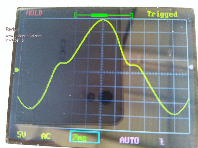 Each time the air gap was increased the sine wave improved, that gave me the idea that the uH was too high, there may well have been more going on than first thought at that time.....(still learning). I plan on revisiting that one later. Unwound the 2 smaller chokes the other day, the wire is still good, will weld up the end brackets to make a clamp, then get some scrap wire and run a few test's and see how that turns out, they might be better suited to this single transformer. Cheers Aaron Off The Grid |
||||
| Warpspeed Guru Joined: 09/08/2007 Location: AustraliaPosts: 4406 |
That waveform looks like magnetic saturation, not sure what is saturating though. The only way to know for sure what is going on is to build a version of the choke saturation testing circuit. Cheers, �Tony. |
||||
| brucedownunder2 Guru Joined: 14/09/2005 Location: AustraliaPosts: 1548 |
Hello Inverter builders. Well, my 30 year old rectifier case has finally became a Busboy/Aaron inverter..well,nearly ! I've stripped the old rusty scavenged rectifier ,saved a few nice heavy trannies and lots of other parts . 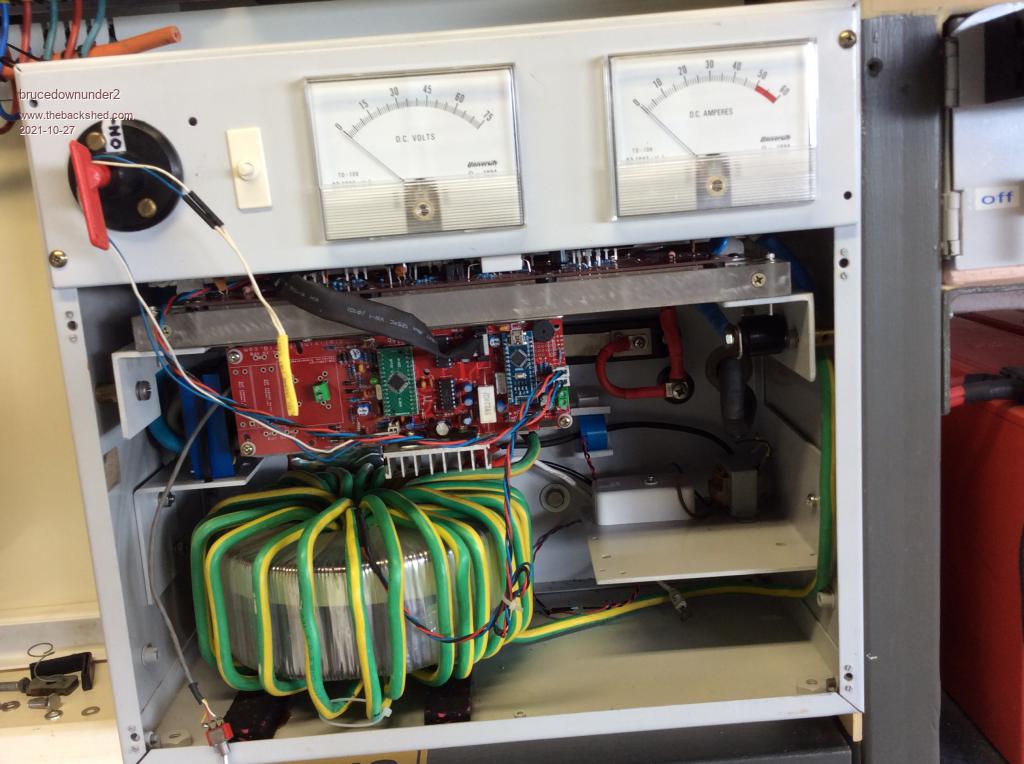 Hope to have it powered-up in a week ,thats a bruceweek,which often is very much longer than your normal week.. Oh, my good friend Aaron is the brains behind this project ,my 78 year old brain, is sort of corroded like some of my batteries !!!. Bruce Bushboy |
||||
| Revlac Guru Joined: 31/12/2016 Location: AustraliaPosts: 961 |
Thats looking very impressive Bruce, the old style gauges should be ok, most house loads are under 50A most of the time. Cheers Aaron Off The Grid |
||||
| Revlac Guru Joined: 31/12/2016 Location: AustraliaPosts: 961 |
Time for an update. Bruce sent some pictures of his inverter build, its almost finished. I'm very impressed with the build quality, nicely done, every inverter build around here is a unique work of art.  Sure these thing's take some time to do a complete build, but it is a great adventure. 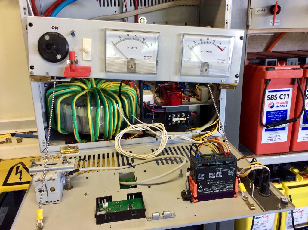 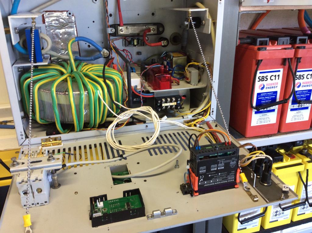 Cheers Aaron Off The Grid |
||||
| Murphy's friend Guru Joined: 04/10/2019 Location: AustraliaPosts: 582 |
Nice, but that metal chain holding the door would worry me. You never know where the links go when the door is shut. Better put some non conductive sleeve over it |
||||
| Warpspeed Guru Joined: 09/08/2007 Location: AustraliaPosts: 4406 |
That is a very neat well thought out build. Well done ! Agree with Klaus, that chain has to go, fishing line or strong string maybe ? Cheers, �Tony. |
||||
| brucedownunder2 Guru Joined: 14/09/2005 Location: AustraliaPosts: 1548 |
OK, thanks for the feedback , totally agree. I have removed the small chain support and replaced it with that braided chalk line ,(polyester or something non-conductive). This part was always at the back of my mind , but maybe I installed it just to get some progress with other parts.. Up to now , it's been a very satisfying project, very long winded, but with hospital every few days.travelling to and fro ,Etc. things around here take ages.(I have kidney failure in one, so that and other things take most of my time. At this stage, I'd like to give a big "THANK-YOU,Aaron" for his support and assembly of the board for me.... I'm about to AC wire the inverter, breakers, external 8 way power distribution board ,Etc.( I'm retired15 years, so my sparky friend is keeping an eye on all things ,even though it's "stand-alone" exclusively. ) Wishing you all a Very Merry Christmas , Bruce and Ilda Bushboy |
||||
| brucedownunder2 Guru Joined: 14/09/2005 Location: AustraliaPosts: 1548 |
Bushboy |
||||
| brucedownunder2 Guru Joined: 14/09/2005 Location: AustraliaPosts: 1548 |
Hello Crew . Looks like I have finished the inverter and all works . Now I'm changing a display of the power being used from the batteries, so the panel mount digital display will be some time arriving.. (the only gripe I have with purchase of internet goods-never mind.) It's been a nice experience building this inverter, my thanks going to the PCB designer and builder , and my good friend Aaron ,who, without his encouragement ,I may not have started, so a big thanks you to those two guys... I built the inverter around an old Ericsson 48 volt rectifier case I scrounged from work many years ago, stripping and sanding, painting.. Tight fit but after a few months of this and that , I somehow managed to make it very nice. This project has taken me around 9 months, but not to worry , I'm very happy to see it finished,. The unit itself has two hinged front panels, which allow me to service all the compact parts fairly easy and two fans in the top for cooling. All AC wiring is protected and adequate fusing is incorporated throughout . Likewise with the DC cables . I have an external earth leakage protected 4 way MCB housing that distributes light and power . I'll post a couple of photos, Bruce.. 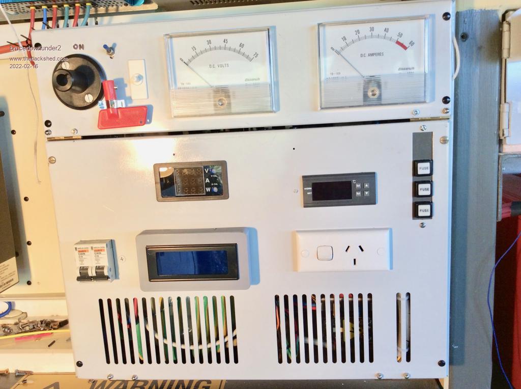 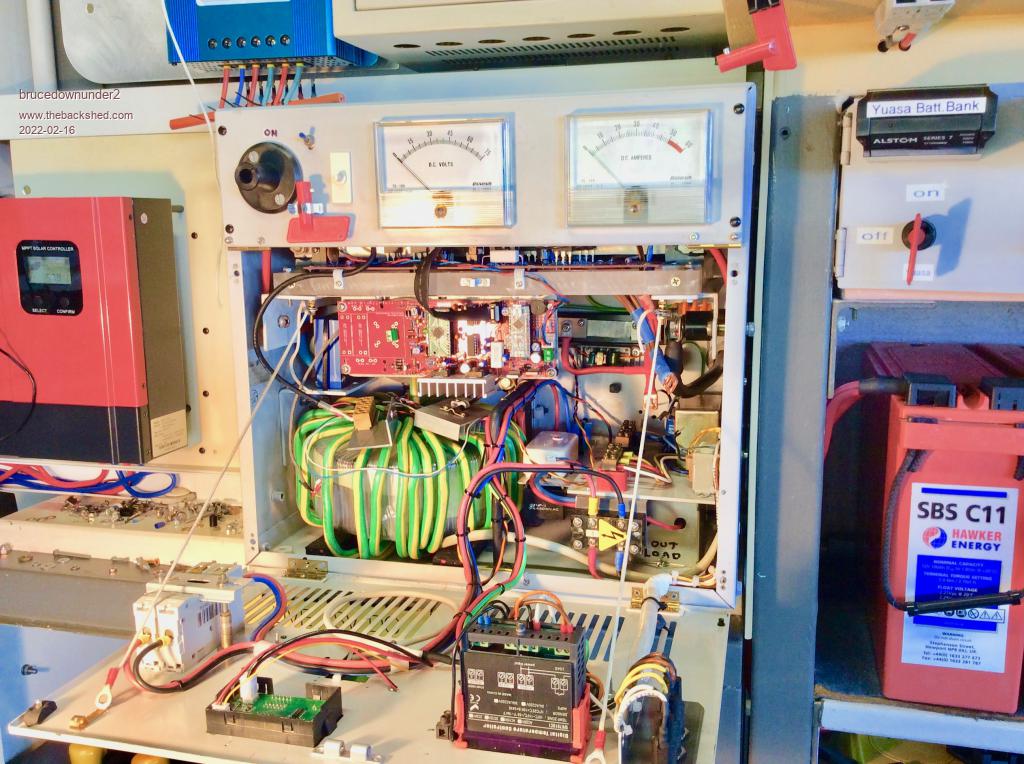 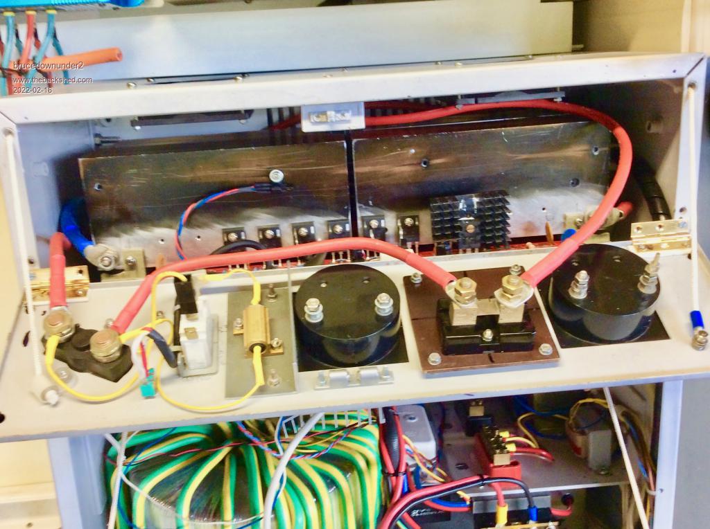 Bushboy |
||||
| Revlac Guru Joined: 31/12/2016 Location: AustraliaPosts: 961 |
Happy to have helped with the build, Always like to see others put there own work and ideas into practice. Certainly is a work of art with the effort and skills put into it.....Excellent Work.  Cheers Aaron Off The Grid |
||||
| Revlac Guru Joined: 31/12/2016 Location: AustraliaPosts: 961 |
Time for an update, sort of. The inverter now has a power meter installed but appears to no be working properly...The new meter is a ...pzem -025 digital multi function meter, now it looks like it requires a 12V power supply unlike most others from the same maker. Problems are, the current is not being read and the voltage is not reading correctly, it is powered by a voltage converter, I thought it might be floating the negative to the meter but after it was check with a meter there was only .3V between the battery negative and the negative out of the converter, so still not sure. Found a video on aliexpress pzem -025 digital multi function meter I Didn't see any voltage converter on the video, but it looked like they were reading 100V? The video is a bit small and fast, difficult to understand. Perhaps someone can look at the video more closely.....it would be so easy if it Didn't need the converter to run it. Any HELP would be appreciated Cheers Aaron. Cheers Aaron Off The Grid |
||||
Chopperp Guru Joined: 03/01/2018 Location: AustraliaPosts: 1032 |
Hi Aaron I couldn't find the video link on the webpage. Getting late. Ok. Found it. It is small & fast BUT you can go full screen (small square box) & there are options (3 vertical dots on the bottom right) for the speed with the slowest option of 0.25. Still probably not too helpful though Brian ChopperP |
||||
