Notice. New forum software under development. It's going to miss a few functions and look a bit ugly for a while, but I'm working on it full time now as the old forum was too unstable. Couple days, all good. If you notice any issues, please contact me.
Murphy's friend Guru Joined: 04/10/2019 Location: AustraliaPosts: 678
Posted: 01:01pm 05 May 2021
Copy link to clipboard
Print this post
Seeing that there is an interesting discussion at another topic regarding inverter PCB layouts I thought I show how I now build mine.
The design is based on Wiseguy's schematic, basically a nano inverter running Poida's code with opto isolated drivers and a final totem pole stage.
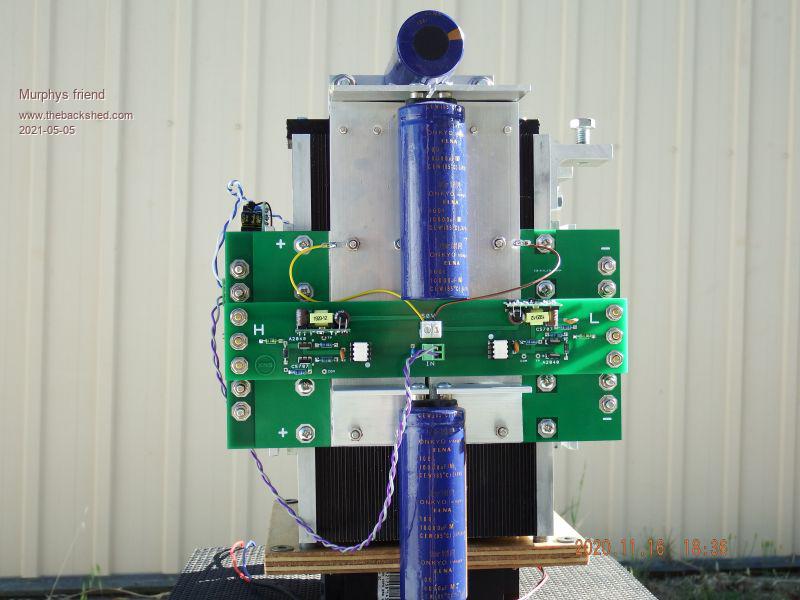
The following pictures should explain better than words;
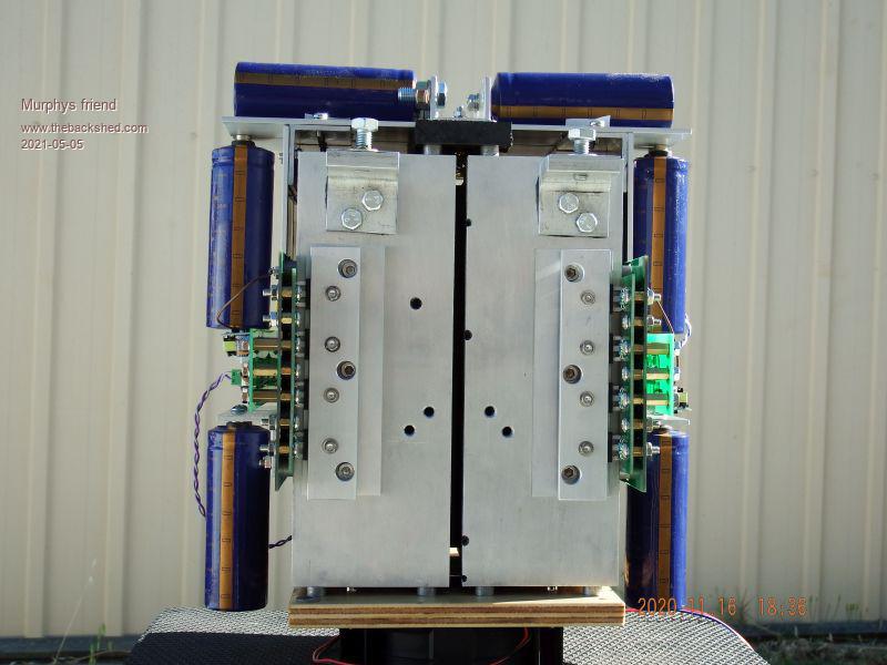
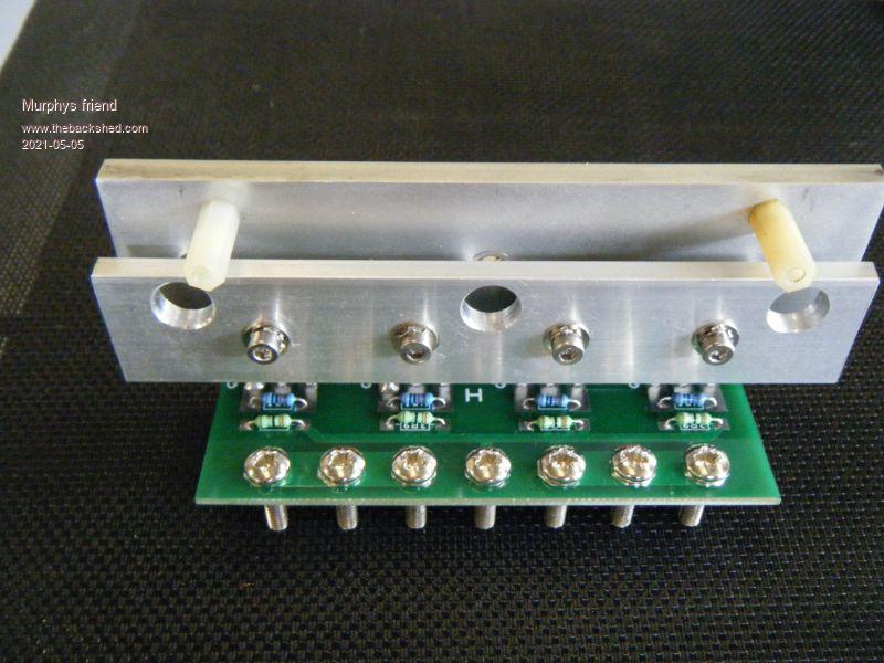
As you can see the heat sink fins face each other with the half bridge boards on each outside. The power tracks are alu 50x3mm flat bar and the capacitors are mounted on those. This allowed the use of 1oz PCB boards.
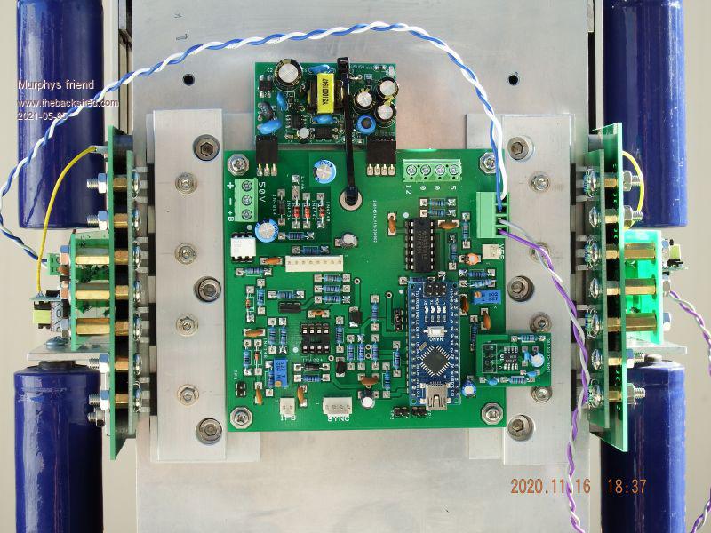
There is a fan underneath the heatsinks. I use an external fan controller rather than the nano for it. The control board fits on a 100x100PCB and incorporates low voltage shut down.
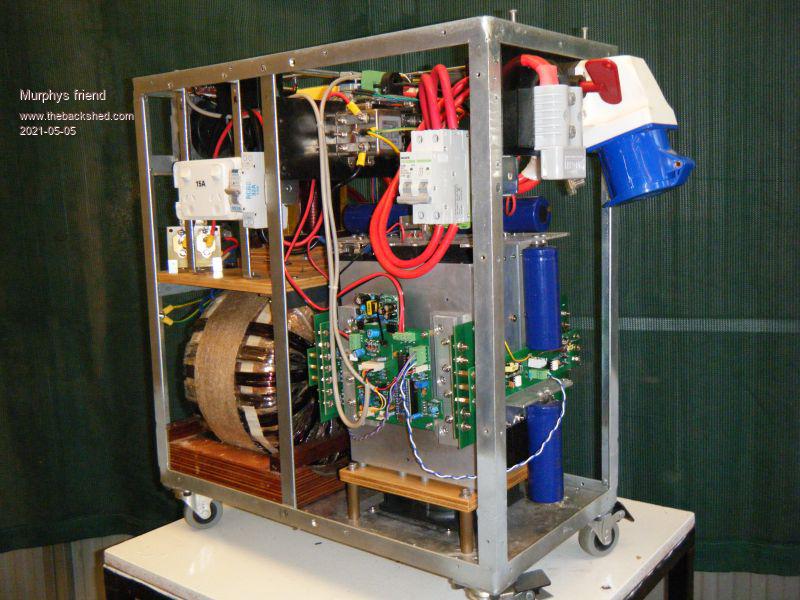
The mosfets are on little carrier boards to make replacement easy. But the surprising robustness of this inverter design has made that so far unlikely. The inverter has a 6KW (2x3KW) double stack transformer and powers all of the house. Nothing I have tried has killed it yet, it just shuts down if I do something silly.
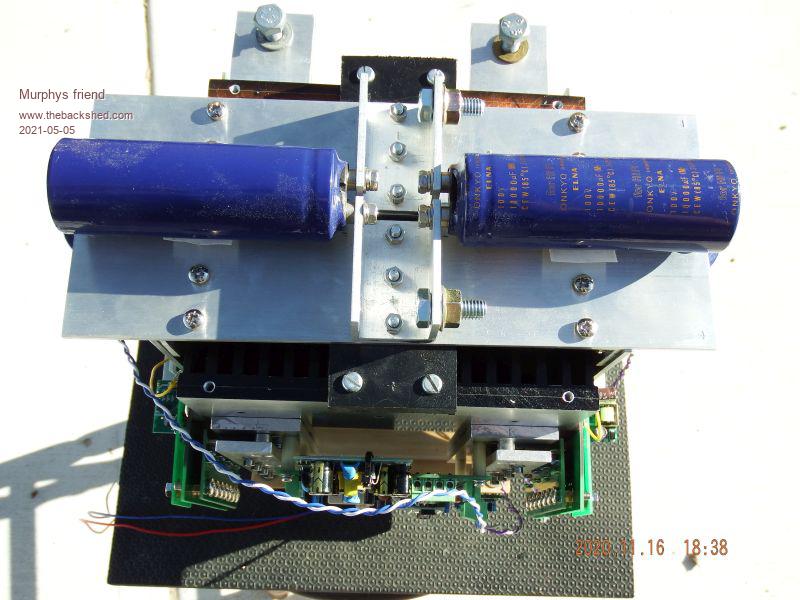
Here is what the whole assembly minus the covers looks:
I'll post a picture of the finished inverter in another topic later.
wiseguy Guru Joined: 21/06/2018 Location: AustraliaPosts: 1296
Posted: 02:08pm 05 May 2021
Copy link to clipboard
Print this post
What I want to know is how the hell you lifted it onto that table ! That is one very impressive iteration of my topology. Thanks for the vote of confidence by building it.
A couple of questions, what gate resistor value did you use ? How accurate is the output voltage control for various loads - what is the largest deviation from the setpoint (240V) ? What choke did you use - I cant make it out from the pictures.
I see that you have solid bars over the FETs & torqued down to hold the smoke in
Did you use separate isolated supplies for each of the 4 legs of the bridge ? What is the idling power ? How warm do your heatsinks get under serious load ?
What is the little sub board on the controller - is that a low pass filter ? Did you try it without the filter - if so what were the results. Do you hear the hum slowly and randomly change or is it rock solid?
The controller is simplicity - well done, the mechanics alas is a bit out of my league !
Sorry for all the questions - I get excited over stuff like this. Edited 2021-05-06 00:15 by wiseguyIf at first you dont succeed, I suggest you avoid sky diving.... Cheers Mike
johnmc Senior Member Joined: 21/01/2011 Location: AustraliaPosts: 283
Posted: 10:58pm 05 May 2021
Copy link to clipboard
Print this post
Thanks for the pics Most impressive
cheers johnjohnmc
Warpspeed Guru Joined: 09/08/2007 Location: AustraliaPosts: 4406
Posted: 11:00pm 05 May 2021
Copy link to clipboard
Print this post
That is a true work of art. I could look at that all day. A very great deal there to learn from.Cheers, �Tony.
Murphy's friend Guru Joined: 04/10/2019 Location: AustraliaPosts: 678
Posted: 08:33am 06 May 2021
Copy link to clipboard
Print this post
Haxby Guru Joined: 07/07/2008 Location: AustraliaPosts: 426