
|
|
Forum Index : Electronics : Power Jack LF + 3kw Aerostar inverter ??kw @ 48v
| Author | Message | ||||
| MasterCATZ Regular Member Joined: 25/03/2011 Location: AustraliaPosts: 52 |
someone was saying the thicker the insulation on the core the more efficient and more performance it has because it switches off faster ? how thick ? they also said a copper sheet should be used to wrap around the coil when it is done to stop electrical interference ? tho this is an audiophile I might possibly have to do this because I have over 30 wifi chargers next to where this is going plus a few other IOT devices Edited 2021-05-09 14:22 by MasterCATZ |
||||
| nickskethisniks Guru Joined: 17/10/2017 Location: BelgiumPosts: 411 |
I did an ozzinverter build with 2 stacked 2000VA cores. About 30kg iron, I think combined it was like 210mm * 121mm high, the inner hole 90mm (I removed 5(10) mm of the original core to have more playing room), +-73cm2 cross section. I did the build with 3.55mm diameter (9.9mm2)wire, about 150 turns secondary. The primary (19or20 turns) 7 strands (9.9mm2) twisted together, so about 70mm2. (I would not recommend this for the primary, and won't do that again) It was very difficult to do the secondary with that wire but not impossible, but at first I was sceptic about paralleling different layers and using used wire. So I bought that wire, but moq was 42kg to get an acceptable price... It had a ratio of about 7.5, as I'm running lifepo4 parallel to LA, and don't mind the secondary voltage drop I have starting around 46V. Because of the very stiff copper I couldn't put a bold in the middle, I would use something more flexible next time. (btw I'm using IR2010 driver (on 15V) chips and IRFP4110 mosfets) I do like having 240VAC when operating tools with induction motors or just any other electronic garden/work tool if you are using long extension cords. What can I power with it? About anything, we don't have a grid connection, and everything except the heating is electric, I was a bit scared in the beginning. But the transformer is a beast, I'm making a second with a smaller transformer at the moment because I ordered spare boards, if something went wrong. I want to start a discussion about the most suitable power board soon, and want to make measurements to examine the limits of different power boards and try developing a new power pcb based on tests. But it's doing its thing, I'm about to reach the 9000kWh mark in a few days, it must be 2 years now, it was end 2018 or early 2019. When cooking, the power demand rises to 5-6000W, with bursts to 8000W, depends on the usage of the oven/microwave. When maxing out the cooking top I installed a rule not to use the oven or microwave, just as precaution, I didn't do the cooling in a decent way, so it would shut itself down. I just screwed some aluminum bars on the mosfets. I think it was 20x100mm cross section, on days like these when there is a demand for heating the house, and decent sun. I'm having a 3000W heating element in my water tank on for about 6-7h without interruption. Without any active cooling it's doing +2000W constantly, and that's mainly because the heat sinking of the mosfets is not done properly. I must say the dryer and washing/dish washer are making over times starting from march. I do have 16 *280W panels on grid tie inverters. I also suspect my electric conduction between the drain of the mosfets and my aluminum is not 100 procent, and causing voltage drop/heat. I did a thread of my build, but not very detailed let me look for the link. Link I would recommend reading the build of RenewableMark, it's gold for those that want to start building their own inverter and very detailed. link Nanoverter: link If I may suggest a thought, I would make sure your secondary winding is powerful enough, maybe sacrificing some no load efficiency and losing a few turns to get an extra parallel layer/winding. Cooling the primary would much easier to do then cooling the secondary (inner layer). Doing the build with 1 core for 5000VA continuous is possible in my opinion, maybe not the most efficient. I think you will get out your cores more this way with the powerboard. With a stacked core you might need a bigger/better powerboard to get everything out the transformer. Btw, did you consider backfeeding? Giving up some charge controllers and switching to grid tie inverters, they could take some stress away from your inverter. Oh maybe a good one to read: Various aspects of home brew inverters http://www.thebackshed.com/forum/ViewTopic.php?TID=9409 Edited 2021-05-10 01:47 by nickskethisniks |
||||
| MasterCATZ Regular Member Joined: 25/03/2011 Location: AustraliaPosts: 52 |
no can not back feed the main house is still on 55 cent export contract until 2028? so it is left untouched and even if I did backfeed the mains here is already over loaded and blowing their transformers every few months and moving away from grid tie hybrid inverters I have a living room full of dead ones , waste of money also instead of grounding of the corners would it be ok to just use some flat steel plate or iron and grind that to be round and just use that for the cores end caps ? increases the cross section ? or does the core have to be made from bands ? also should some heat shrink be slipped over the start and finish ends so they are well insulated 0 - 240v potential difference ? Edited 2021-05-10 12:29 by MasterCATZ |
||||
| MasterCATZ Regular Member Joined: 25/03/2011 Location: AustraliaPosts: 52 |
does anyone know the maximum size of the hole in the center ? because it bugged me not having the primary making contact over all of the core using the 50mm2 cable I widened it up so I can use 25mm2 side by side single layer it has a 90mm opening after being wound is is this bad? or is having the center gap of the primaries the goal 50mm2 had 75mm gap 230mm external 130mm internal 70cm2 21 Primary Turns 2x 25mm in hand = 50mm2 circuit 250AMP continuous 166 Secondary Turns 4 Layers 2.54mm2 = 10.18mm2 circuit 50 AMP continuous 12kw continuous capable if cooled ? 1:7.9 ratio 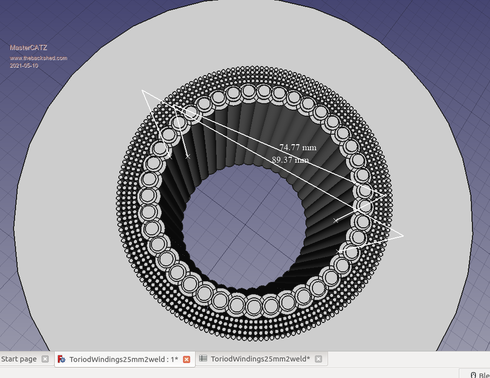 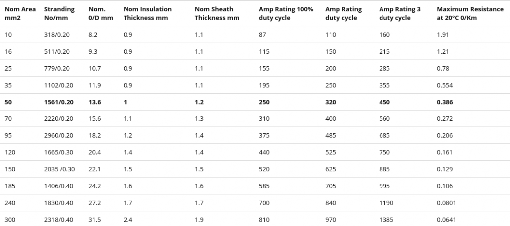 Edited 2021-05-10 17:13 by MasterCATZ |
||||
| Clockmanfr Guru Joined: 23/10/2015 Location: FrancePosts: 427 |
Hi, All the questions you are asking are in the 2nd Edition OzInverter book, and yes its on its way to Australia. The core is made of, usually 0.3mm thick silcone iron/steel, quality is important thats why we test the core during winding. Your winding drawings look good on paper, but and a big but, in practice you should use them as a guide only as the corners/90 degree bends, of the cable bulk out a bit and things through the hole get real tight. Just get the cables through the hole, every time a cable passes through the hole it is One turn. Remember that anything in that hole, ie a holding bolt becomes a turn and is active so insulate it. Size of hole, depends on the stack ie, the thickness, 130mm hole is okay you can stack a bit more and a 90mm hole left after winding would be heavenly, i normally find that i can just get a 12mm dia holding bolt though my wound toroids once finished. AC coupling, because the OzInverter is a H bridge design the voltage can flow backwards, ie, your 230vac can when raised by GTI's, push back and therefore charge your batteries and with GTI's the OzInverter just starts the Mini Grid and the GTI's take over supplying the Mini Grid. So you are using the GTI's to run your appliances and therefore minimum use of the batteries. From ....... http://www.bryanhorology.com/off-grid-and-your-own-mini-grid.php A very cost-effective solution for handling that 19kW of power from the PV panels arrays, is to use what is called 'AC Coupling'. Houses that you see around the World with PV on the roofs will be using GTI's, (Grid Tied Inverters) that take the PV DC output and change it to AC and feed it back at a few volts more into the Mains Utilities Grid for that Country. These GTI's are slave machines and need to see the correct AC voltage and the correct HZ frequency, so to get their internal electronics/transformer to operate before they will feed into the Grid a few volts over the Mains Utilities supplied voltage. There are many Good Quality GTI's available second hand, i use fleebay etc, and i prefer GTI's with a toroid transformer, see below photo of previously used SMA's........ . 150 to 300 Euros each. Now our 48vdc 'OzInverter' creates a very stable 240vac or 120vac at a stable 50H or 60HZ, depends on your country domestic voltage, and therefore allows 'AC Coupling'. The GTI's back charge through the 'OzInverter' to the battery bank any surplus power not being used on the OFF GRID or we call our 'OzInverter' created MINI GRID. Three methods of controlling the back charging from GTI's is possible for 'AC Coupling'. A. Use the Internal codes/settings in the GTI's to sequential shut down when a specified ac output voltage is reached. This works reasonably well with my system as some installations GTI,s are up to 400 meters away from the 'OzInverter' and batteries, and the batteries do push back slightly, but this depends on the cable voltage sag. B. Use dc voltage comparators circuit to shut down the GTI ac side with a relay when the DC battery voltage rises above a charging rate voltage. But you will need to run a data cable to all your installations, and again allow for voltage sag. C. Use PWM dc controllers that are connected directly to the 48vdc battery bank. These Diversion controllers, (Morningstar Tristar PWM at about 200 Euros each), will regulate the charging and any excess power when the batteries are full and will dump/divert to other permanently connected sources, ie, Air Heaters 2kW each or Hot water heaters, underfloor electric heating, etc. The above are a cost effective and very reliable system. A is used most, and C is my guaranteed safety system. Where i do not have access to the GTI internals, then i use B. For a 19kW PV Array I prefer using 2off 1.7kW & 4off 2.5kW GTI's for 14kW, and using DC Charge controllers for the 5kW as these can gently finish charging that precious 48vdc battery bank. NOTE, I have not used a HF, High Frequency GTI, because second hand old heavy toroidal types are easily obtainable and very cheap, plus you get to use the GTI internal MPPT . 'Oztules' and others have experimented with HF types and do not find any real difficulties. NOTE. Its best to use GTI's at a max output of 2.5kW as above this the GTI tends to surge on a long cable connection. I trust this helps. Everything is possible, just give me time. 3 HughP's 3.7m Wind T's (14 years). 5kW PV on 3 Trackers, (10 yrs). 21kW PV AC coupled SH GTI's. OzInverter created Grid. 1300ah 48v. |
||||
| Murphy's friend Guru Joined: 04/10/2019 Location: AustraliaPosts: 583 |
please don't use steel or iron or anything metallic for that - it only invites eddy currents and increases your core losses. I used 6mm plywood disks for that, worked a treat. A suggestion: if you limit your questions to two or 3 max per post you might get more answers. I find it tiresome to try to answer more than that in one post. |
||||
| MasterCATZ Regular Member Joined: 25/03/2011 Location: AustraliaPosts: 52 |
that brings me back to the question about the "someone was saying the thicker the insulation on the core the more efficient and more performance it has because it switches off faster ? how thick ? " does anyone know the ideal thickness to separate wires from the core ? so far it seems I can go at least 6mm? I can easily 3D Print something to use as core cap / wire guides then the additional solar stuff here can not be connected to grid, doing so we loose our 55 cent export on the main house also many of the AC coupled inverters mostly died in first year , I think only 10% of my Enphase Micro Inverter's are even working now I thought I would take this question to the extreme , is their anything wrong with a large hole in the center 400mm? apart from using more space? does this affect the eddies ? I feel it will help with cooling and faster hand winding bicycle rim easily travels through it ? seems to use exactly same amount of copper ? still the same 70cm2 cross section using same mm2 worth of cable just everything single layers 500mm external 400mm internal doing this I could use 6mm2 solar cable and 2.5mm2 copper winding's (just realized I was using radius measurements before ) 155 4 in hand 2.5mm2 Secondary 236m 210 1 in hand 6mm2 primary 80m tho I am still trying to work out how making it higher helps ? something 450mm high uses 24 Secondary Turns 24m 3 Primary Turns 3m ? pretty sure I am missing some maths their somewhere does their have to be a metal bolt through the center ? 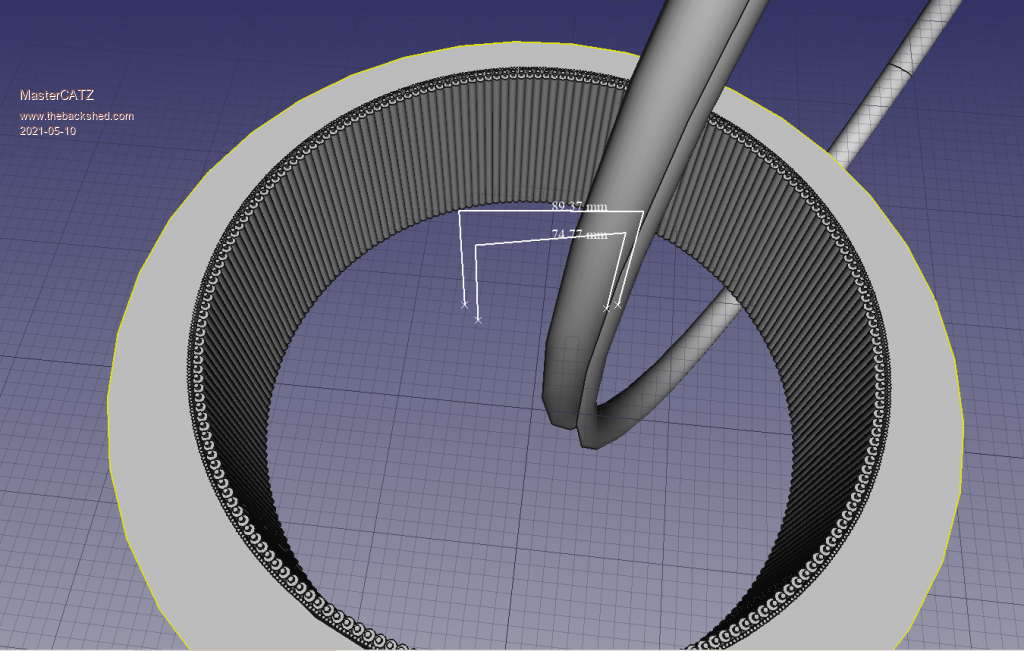 Edited 2021-05-10 22:46 by MasterCATZ |
||||
| nickskethisniks Guru Joined: 17/10/2017 Location: BelgiumPosts: 411 |
I don't really understand your question, but if I had to guess it was more of a problem (capacitive coupling?) with the warpinverter because it initially had no series inductor and could be avoided by adding more isolation. I just epoxied (also a little glass fiber) the core and added 2 layers capton tape, what you sometimes see with a commercial transformer is some kind of plastic cups that cover up the core, I saw no more than 1mm thickness. The only proven benefit would be the rounded edges. Be careful with 3D printed material, pla and abs have low melting points, I used pla to make a coil former for my inductor, but you can't use it above 50degreeC. A next version is with abs, so a slightly improved temperature but not much. I don't know but I think you misunderstand it, you can create a separate "mini grid" with your inverter, it is not connected to your grid connection. But it is possible with the ozz inverter or any other LF inverter, to connect grid tie inverters on it. So if your grid tie inverter is producing more power then you are loading your inverter, it will charge your batteries. But you need to be careful, because there is no feedback to stop the charging. Like Clockmann explained You need some "simple" additional diy hardware/trick. Enphase has a good warranty policy, so they sent you new inverters if you have a problem with them. No it's not a problem, it's just an easy way to secure your transformer. Did you consider the following: A core with the dimensions of 500x140 and 400 inner diameter, has a volume of about 10 liters (9884cm3), and weighs about 7.8kg/liter, so that would be a core of roughly 78kg!! If that's not a problem you will have more no load losses too, because that depends on the weight also. So you won't be able to make those out your aerosharp cores if that was the plan. |
||||
| Warpspeed Guru Joined: 09/08/2007 Location: AustraliaPosts: 4406 |
Transformer capacitance is not an issue if the transformer is driven with a 50Hz sine wave. Its a huge problem if you try to drive a large transformer that has one or more high voltage windings with a square wave, where there are very high instantaneous changes in voltage expected. That produces theoretically almost infinite current spikes in the primary. Fitting a suitable choke to a PWM inverter solves the problem completely, nothing needed at the transformer because the transformer should only see a pure sine wave voltage and current if the choke is working properly. Cheers, �Tony. |
||||
| MasterCATZ Regular Member Joined: 25/03/2011 Location: AustraliaPosts: 52 |
"you will have more no load losses" so what will be causing the extra no load losses ? and what would be stopping me using the areosharp cores are they not all bands wrapped up ? space / weight is not an issue 1m3 box for the core and I do not see how the weight will change apart from core stacking? all of the wire calculations I tried said the wire lengths were going to be the same regardless what the internal external sizes were so no extra costs or weights I am planing on just undoing the external spot weld and letting the bands uncoil and expand inside of a jig then respot weld it in place if their are no performance losses for having a wider core I would try it at least someone has too ? I have some other dead inverters I can test with |
||||
Haxby Guru Joined: 07/07/2008 Location: AustraliaPosts: 418 |
The losses are in the core. Bigger core= more losses.... So to have your cake and eat it too, you need to match EVERYTHING! Wire size, core size, hole size. The solution is a very densely wound transformer with not much room left in the hole. But if you are burning off excess solar, I wouldn't worry about idle power so much. Letting the core unwind is a bad idea. It will be hard to pack it tight again. Edited 2021-05-11 19:41 by Haxby |
||||
| nickskethisniks Guru Joined: 17/10/2017 Location: BelgiumPosts: 411 |
Hi, In theory there is nothing wrong with your idea. Your idea is to rewind your aerosharp cores and to get the a 500mm core, but you won't get the 70 cm2 window if you do that. You will need to have about 4 aerosharp cores to achieve what you want. You probably get around 30cm2 window with 2 rewinded aerosharps. You need to see it like this, if you have a certain core, the iron has a certain volume, and certain winding area. If you rewind your core to a wider core, the volume of the iron stays the same, but the winding area will decrease. The opposite is also true but not wanted. A rough estimation for core loss is about 0,5-1W/kg. Edited 2021-05-12 04:13 by nickskethisniks |
||||
| MasterCATZ Regular Member Joined: 25/03/2011 Location: AustraliaPosts: 52 |
ok so the goal is to have a tightly wound hole ? not having much luck freeing these cores they are stuck down good I might have to buy a minni crowbar to try and get under them , can not get the other 3x coils off the case either so no room to leaver , any solvent that can be used ? and of cause the one angle I can not take photos is the transformers label it is hard against the case tho I might be able to get the snake cam in 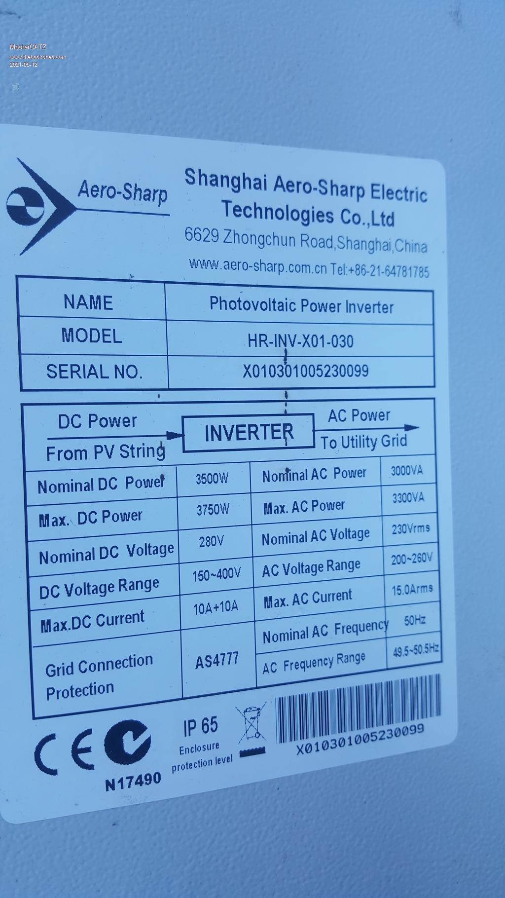 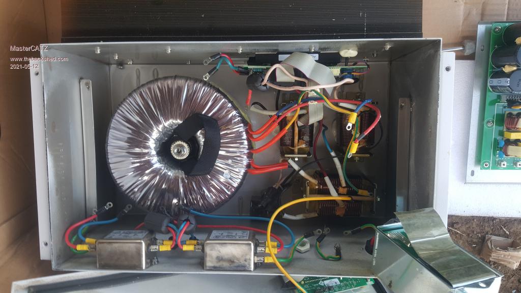 |
||||
| Haxby Guru Joined: 07/07/2008 Location: AustraliaPosts: 418 |
Ah that's an Aerosharp not Aerostar. All good. Plenty of experts here on that brand. Getting the transformer out is easy! First disconnect all wires, then turn the box over, lift to about 600mm height then drop it on the ground! The toroid will dislodge and fall out. The screw and epoxy centre stay with the box. That's how I did 7 of them so far and they all turned out great. You might want to work up to 600mm height drops depending on how well it is stuck down. I'll video my next one. I did mine on a grass lawn so there was no damage to the windings when it eventually popped out. If you were to do it on concrete, you would want some styrofoam or something to catch the transformer. Are you in Melbourne per chance? |
||||
| Haxby Guru Joined: 07/07/2008 Location: AustraliaPosts: 418 |
Now you have two of them yes? Both 3kw? Your next question is whether you should: Choice A: Unwind both, stack the cores and re-wind as one. That's a big job! A lot of work! or.... Choice B: Just unwind the outer most winding, keeping the primary intact, and add the thick 48v winding on top. That's a lot less work! If you choose A, you will have a very efficient large heavy transformer that doesn't use much idle power. If you choose B, you won't have to do much work. But your loads will have to be balanced between two transformers, and for optimum voltage regulation you might need two driver boards, basically building two separate 3kw inverters. |
||||
| MasterCATZ Regular Member Joined: 25/03/2011 Location: AustraliaPosts: 52 |
well we ended up getting the torch onto them and heating the box up 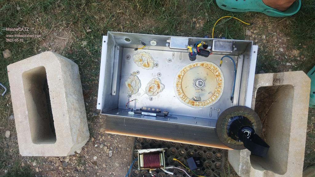 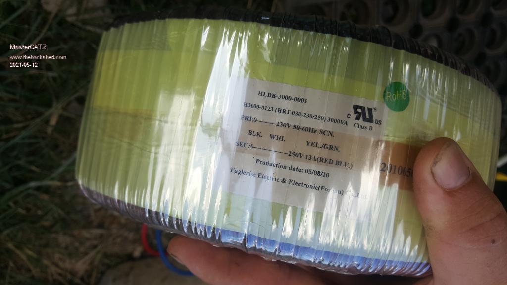 unfortunately I need a minimum of 5kw unless I can parallel the coils easily ? any way to put the ozi inverter in another case to drive those coils inside their own separate inverter box's as is ? or can ozi inverter be paralleled AC side ? can it couple ? apart from that yes will be combining the cores now I am wondering where I got Aerostar from if a mod can fix the topic name to aerosharp that would be greatly appreciated Edited 2021-05-12 18:16 by MasterCATZ |
||||
| Haxby Guru Joined: 07/07/2008 Location: AustraliaPosts: 418 |
You shouldn't couple the AC side so unwind them fully. Stacking them will be the way to go. Good luck. |
||||
| nickskethisniks Guru Joined: 17/10/2017 Location: BelgiumPosts: 411 |
You won't be able to run 2 ozz inverters in parallel without some modifications. Perhaps it's an idea to use 1 brainbord as master running 1 powerboard, and 1 mosfetdriverboard (slave getting it's pulses from the master) running the second powerboard. Separate primaries but paralleled secondaries maybe after the filters. You would be the first doing this on this forum I think, solar Mike is planning to do something like this. Stacking 2 cores would create a monster transformer, when done right, giving more power then the 2 transformers paralleled. The only limit then would be the H bridge. Maybe you could rewind a transformer for 5000W by creating a bigger core hole allowing more/thicker wire and by using the hole completely. |
||||
| MasterCATZ Regular Member Joined: 25/03/2011 Location: AustraliaPosts: 52 |
any one is Australia want a ozinverter PCB's ? I swear I read they were now being sold populated more so peeved that a component list was not provided so parts could have been pre ordered , so now I am back to waiting for slow Chinese shipping anyhow I may as well just buy their fully assembled boards book is full of dead links also |
||||
| noneyabussiness Guru Joined: 31/07/2017 Location: AustraliaPosts: 506 |
inverter board Not sure if its already been mentioned, i use the above personally, layout is good and as long as you do a few minor tweaks its incredibly tough... I've had over 9.5kw through it for around half an hour, yes the fans were working, yes it got warm... but did it... The transformer is a 10kw 32v/240v factory wound " duel C core " by dyne... would have liked a 28v / 240v but it was originally wound for a PJ setup... I think it works !! |
||||
