
|
|
Forum Index : Electronics : 100 Volt Modular H-Bridge Designs
| Author | Message | ||||
| Solar Mike Guru Joined: 08/02/2015 Location: New ZealandPosts: 1125 |
Am building two versions of this, first having tight coupled drivers on each mosfet, second using a totem pole high current booster driving the three mosfets in parallel. Second less complicated variant shown below. Changes: 1: Input pwm drive has been changed to interlocked push-pull, where a pair of buffers on the cpu board supply a plus\minus drive that includes the dead-time delay. To accommodate this the old simulated opto driver from ver 1 has been replaced by one that allows up to -18v on its input. This allows an interlock mechanism where there will be no drive output if their input signals are the same. Because this design allows multiple power modules to be paralleled for higher output power, it is not recommended to use ordinary "opto" driver chips like the 10 year old FOD3182 or similar, they have too much delay variation between chips, making any synchronous operation very hit and miss. 2: The totem pole driver is a variation of Wiseguys circuit, he has used on his inverter, I have added additional components to help alleviate dv\dt shoot thru on the L0 part as I'm not using a -ve ground bias. Don't replace the spec'd transistors with tip31/32, they are too slow and low in gain for this application. The original Ver1 will also be changed to use the newer UCC23313B driver chips, so I can swap between boards to see which performs the best, or produces the less smoke. 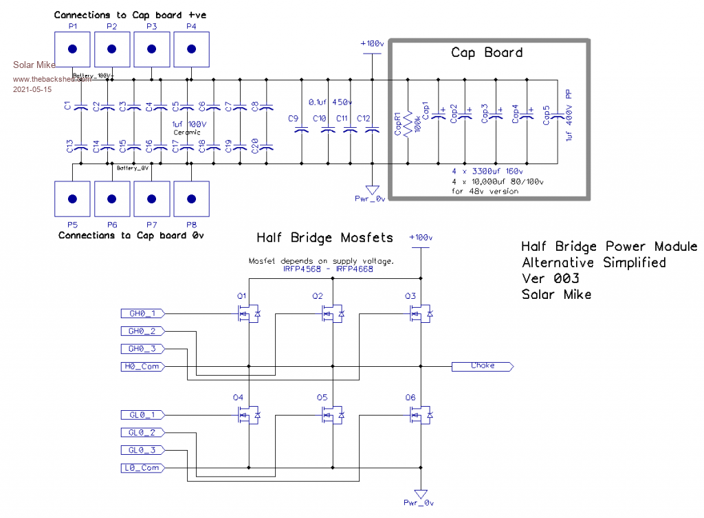 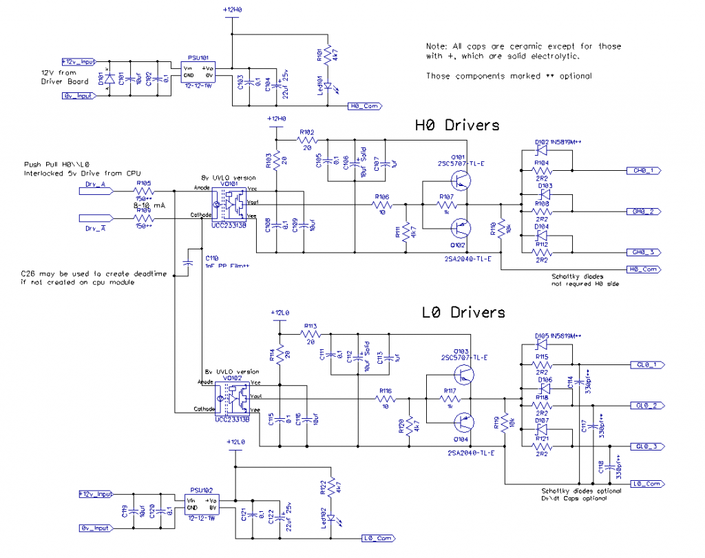 Edit C110, not used here as the dead-time will be created on the Master CPU board, have allowed a place holder for it on the pcb, should anyone want to use a different master driver with no dead-time output and driving a pair of 1/2 bridge modules only. Cheers Mike Edited 2021-05-15 14:31 by Solar Mike |
||||
| Solar Mike Guru Joined: 08/02/2015 Location: New ZealandPosts: 1125 |
PCB for above, couple minor circuit changes, will post later after doing some more checks. 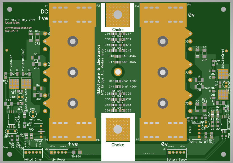 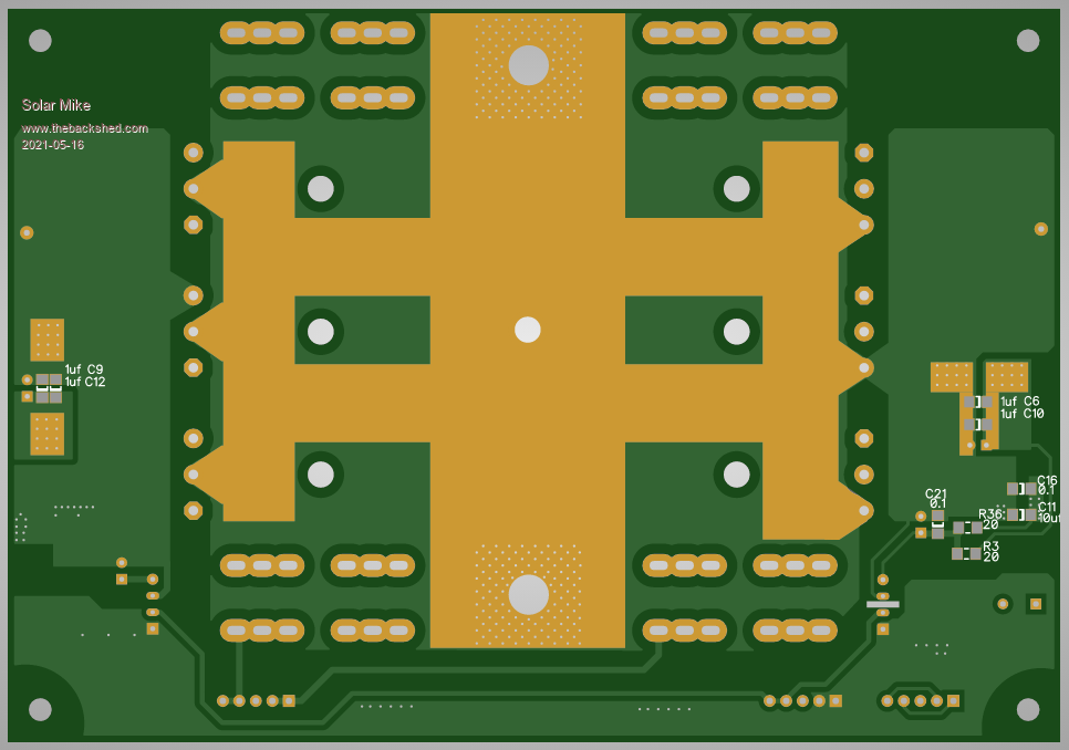 Mike |
||||
| poida Guru Joined: 02/02/2017 Location: AustraliaPosts: 1389 |
I see a few design elements in the schematic that are interesting. The low value caps across Gate and Source might be useful to control shoot-through. To show the effect I would want good DSO probe setup. will it be possible to use the bare probe and ground spring held in position by hand, with the probe tip on a Gate and the spring on Battery -VE? If so, you will get a good signal. In testing could you probe the shoot-through with and without these caps? What is the part number for the 12V isolated dc-dc converter? wronger than a phone book full of wrong phone numbers |
||||
| Solar Mike Guru Joined: 08/02/2015 Location: New ZealandPosts: 1125 |
Isolated 1W PSU Spec , search on AliExpress for b1212s-1W, only couple $ each or less, have never found one that didnt work, note they need a minimum load of a few mA; I normally use a led on their outputs. The use of a small G-S ceramic cap is but one technique, noted that this places more stress on the driver as the cap value increases, what has a greater affect is a very low impedance driver, close to the gate as possible, if the gate is clamped to source by the driver, then its not possible to increase the gate voltage to cause the device to conduct, further away the driver the pcb wiring then acts as a transmission line and it takes a finite time for the pulse to be shorted, in which time the mosfet may turn on or oscillate. Probes are always a hassle, I sometimes use a piece of 50r coax lead with open ends, and solder direct to the mosfet pins; will add a masked strip along the pcb edge behind the pins to make it easier to probe directly with hand held probe (without earth leads etc)... have left place holders for those caps off the pcb, will put them back. Cheers Mike Edited 2021-05-17 11:37 by Solar Mike |
||||
| Warpspeed Guru Joined: 09/08/2007 Location: AustraliaPosts: 4406 |
Just double check the pin outs and footprint of those little dc to dc supplies, I have been caught out a few times, there are some odd ones out there. Cheers, �Tony. |
||||
| Solar Mike Guru Joined: 08/02/2015 Location: New ZealandPosts: 1125 |
Good point, just checked the ones I have here, MornSun and EVISun; both have correct pinout as per that pdf. Edit: Those driver chips UCC23313BDWYR only cost a few $ each direct from the Texas Instruments online store, I ordered 20 three days ago + $10 shipping and arrived today. Not bad, will certainly get more components from them. Edited 2021-05-17 15:34 by Solar Mike |
||||
| Solar Mike Guru Joined: 08/02/2015 Location: New ZealandPosts: 1125 |
Have a final schematic and pcb for the alternative simplified half-bridge power module, no changes have been made on the bulk capacitor board. Few changes made are; removal of 10K resistors on mosfet gates, not required as there is already a path to source via the buffer transistors. Couple of extra bypass caps added here and there. With the cap board bolted on and if 1oz copper is used for both, 150 amps would be a conservative upper limit, no busbars etc. There is room to add busbars, however the 8 bolt on terminal posts for the cap board then become a limiting factor. This design is not for high current anyway, but to have multiple parallel modules combined in a synchronous arrangement to get the desired power output. Initially I was going to use 2oz copper, but with the first test version will go for the cheaper 1oz. Will next alter the first version using gate drivers on each mosfet to use the same UCC23313B coupler, then send them off to be made. As it stands its not really compatible with the CPU + driver module that Poida has created, so I will have come up with an alternative as the next stage in development in order to test the design. 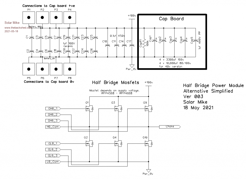 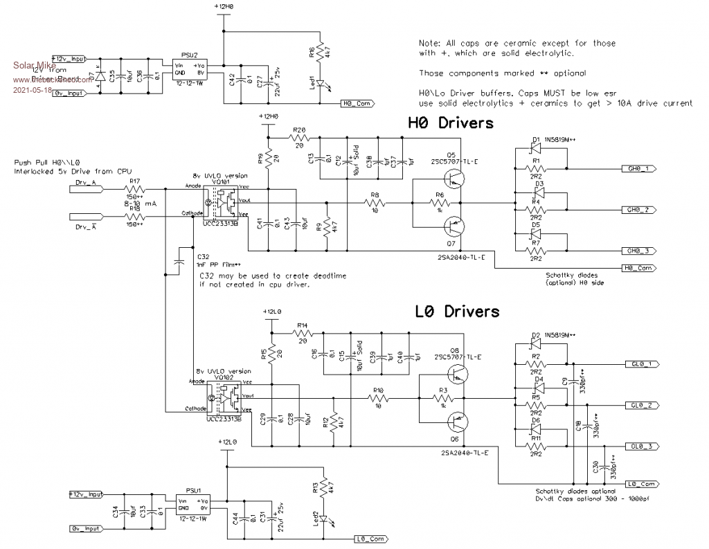 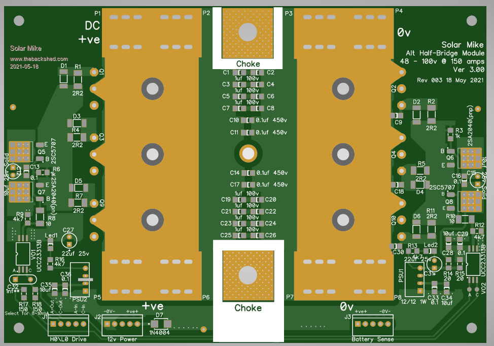 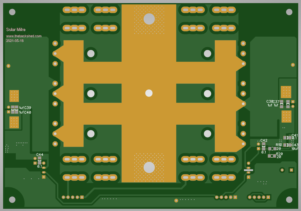 Cheers Mike |
||||
| Solar Mike Guru Joined: 08/02/2015 Location: New ZealandPosts: 1125 |
Have finally made changes to the first more complex design with a driver/mosfet; added the same cross coupled UCC23313 simulated opto-couplers to the input, will have to now modify the schematic to match. Think I have settled on a suitable driver module incorporating deadtime etc for these, will make this a small sub board that plugs into the main CPU pcb. 10 Pins (0v, 5v, +12v, CPU_H, CPU_L, CPU_Enable, Out_H0L0, Out_H1L1) Will also create a 2nd capacitor pcb that uses different sized caps before sending the gerbers off. Half Bridge modules are 113 x 162mm Top: 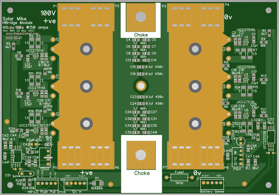 Bottom: 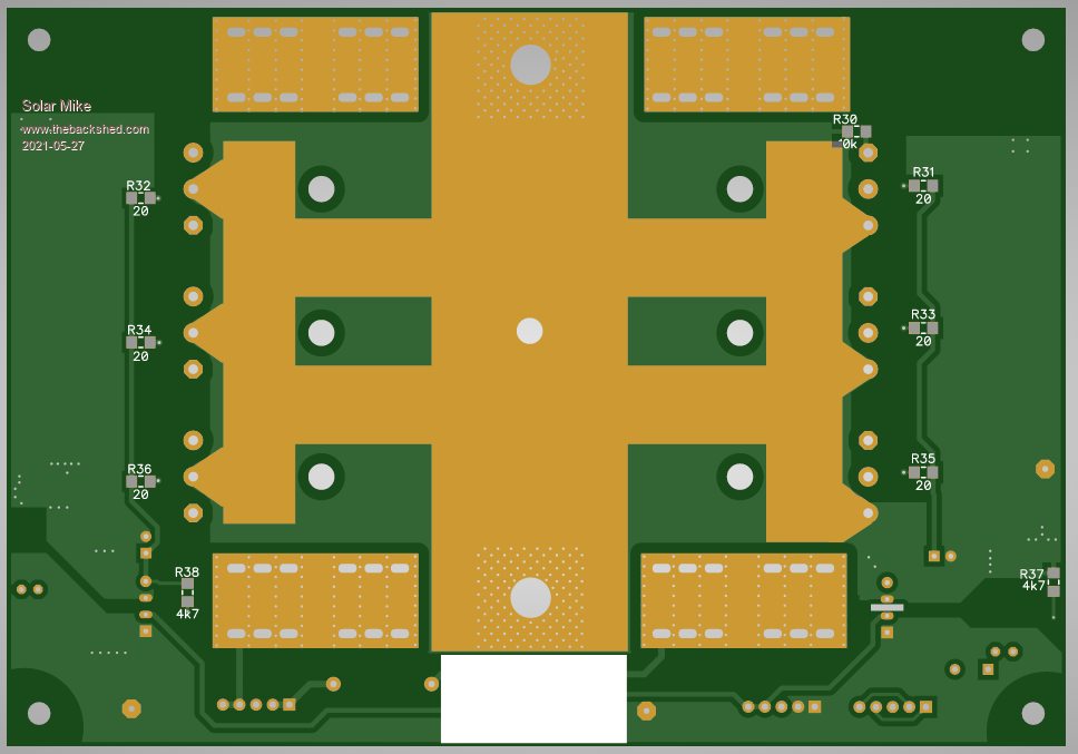 Alternative layout: 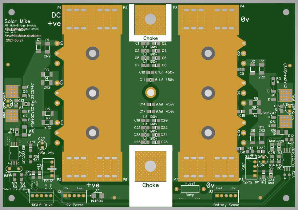 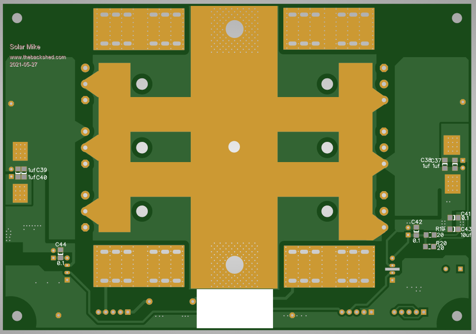 Will post gerbers once schematics updated. Cheers Mike Edited 2021-05-27 12:57 by Solar Mike |
||||
| Solar Mike Guru Joined: 08/02/2015 Location: New ZealandPosts: 1125 |
Circuit: 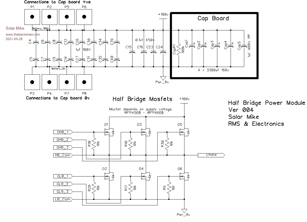 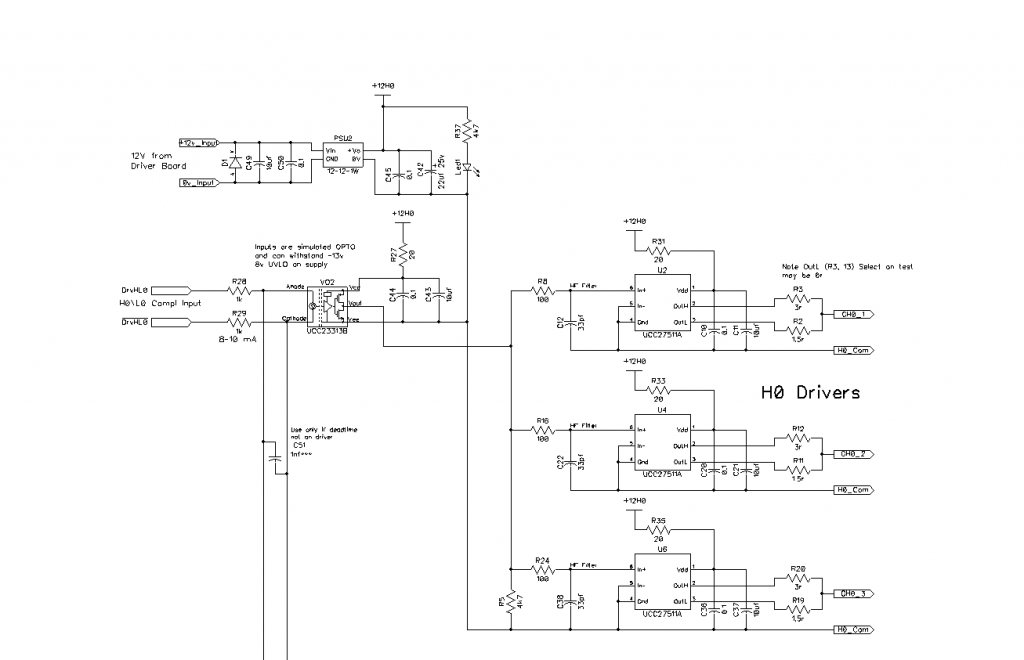 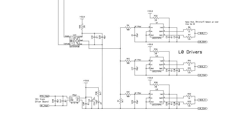 For the CPU module, I would like to have a play with an alternative to the Arduiuno nano, have ordered a pack of Rasberry Pi Pico boards to have a play with, have never programmed in mico-python, maybe too slow, however the cpu is quite fast, will see... Cheers Mike Edited 2021-05-28 11:19 by Solar Mike |
||||
| Warpspeed Guru Joined: 09/08/2007 Location: AustraliaPosts: 4406 |
Looks good Mike. Cheers, �Tony. |
||||
| Solar Mike Guru Joined: 08/02/2015 Location: New ZealandPosts: 1125 |
Just noticed an error on the note for the L0 1.5r gate input resistors, it should read: R7,15,23 can be 0r as the mosfets have an 1r impedance and the driver has a 0.375r output. The lower these resistors the better resistance to false turn on from the H0 stage. When I test the board will try both 1.5r and 0r Mike |
||||
| Warpspeed Guru Joined: 09/08/2007 Location: AustraliaPosts: 4406 |
Resistance also provides some damping to the parasitic inductance and capacitance. See how it goes, but if you see ringing and overshoot on the gate waveform, adding some resistive damping or a ferrite bead can be beneficial. Its all a tradeoff.... Cheers, �Tony. |
||||
| Solar Mike Guru Joined: 08/02/2015 Location: New ZealandPosts: 1125 |
Indeed, will be interesting to compare both versions of the board to see what benefit is to be had from using these tiny driver chips with extremely short path lengths, compared with the Totem Pole drivers effective longer wiring path. Those tiny chips are a right pain to solder. Mike |
||||
| Murphy's friend Guru Joined: 04/10/2019 Location: AustraliaPosts: 584 |
Mike, just a tip re your schematics. Decimal points have the habit of disappearing to older eyes so, instead of writing a 1.5r value for a resistor try the more generally used 1R5 nomination. I see you are using my suggestion with capacitors already  . . |
||||
| Solar Mike Guru Joined: 08/02/2015 Location: New ZealandPosts: 1125 |
Try this, may be easier to read. Edit 2nd attempt; Schematic.pdf Cheers Mike Edited 2021-05-28 20:39 by Solar Mike |
||||
| Solar Mike Guru Joined: 08/02/2015 Location: New ZealandPosts: 1125 |
Have sent gerbers for all pcbs + several additional cap bank cards to JLCPBC Cart, now have to do a simple Dead Time driver module to include in the above, to save postage. Drawing two designs for this now, will use the Si8234AB-D-IS1 chip to get the variable timing as one module, the other will use an LM5105MM/NOBP chip, they both have similar functionality but stocks are running low everywhere, so I think 2 driver cards is a good idea incase of shortages. Expect each will be a small plug in pcb about 50mm x 50mm I have received the Pi Pico boards, whether I can use them for the CPU is another story. Here is another Cap Module to use smaller value electrolytics, have placed right angle connectors on the pcb, so I can stack the boards vertically using a 0.5mm x 45mm wide copper shim as busbars. 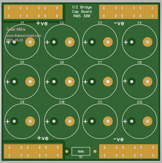 Cheers Mike |
||||
| BenandAmber Guru Joined: 16/02/2019 Location: United StatesPosts: 961 |
Has anyone considered using lots of the cheap little super caps around 25 f or so 50 for 50 bucks here and there Sorry if this ends up being a dumb question has to be a village idot and got to learn some how so maybe two birds with one stone?? Lol be warned i am good parrot but Dumber than a box of rocks |
||||
| nickskethisniks Guru Joined: 17/10/2017 Location: BelgiumPosts: 417 |
Looking forward to this project, where are you buying those right angle connectors? |
||||
| Solar Mike Guru Joined: 08/02/2015 Location: New ZealandPosts: 1125 |
Hi Ben, Caps are 160v rated for my inverter which is running at 100v; those super caps generally are 5v or less each, so would require many in series to get the required voltage rating. Placing them in series is an issue in getting all their voltages to balance during large charge and discharges, requiring some sort of BMS system to manage them.... too difficult. Cheers Mike |
||||
| Solar Mike Guru Joined: 08/02/2015 Location: New ZealandPosts: 1125 |
4mm Right Angle Connectors Foil for vert BusBar Last lot I purchased were tin coated brass, wouldn't use them above 30A, some others on AliExpress maybe copper (great) or steel (crap); half the time sellers haven't a clue what they are selling, so you don't know what will turn up. Cheers Mike |
||||
