
|
|
Forum Index : Electronics : Circuit to flash one LED then the other at about a second each.
| Page 1 of 5 |
|||||
| Author | Message | ||||
| bob.steel Senior Member Joined: 27/02/2020 Location: AustraliaPosts: 188 |
I have a 28 volts supply. I have an LED based with blue lamp and white lamp. 3 wire one common. I want to flash between blue and white at 1 hertz when the power comes on to the lamp. I found a similar circuit in Forrest Mims book but he seems to use P channel MOSFETs. I want to use N channel MOSFETs because I have surplus. I've been A over T messing trying to design something but its a bit bigger than I am. I'm looking for values of resistors and capacitors to plug into this astable circuit to accommodate the voltage. Can I get some help please? I attach a scan of what I have atm [1]: 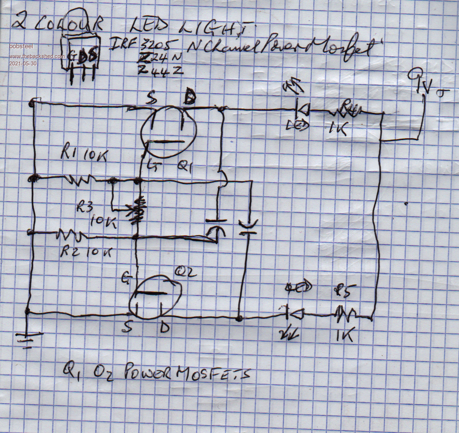 Edited 2021-05-30 20:26 by bob.steel |
||||
| Solar Mike Guru Joined: 08/02/2015 Location: New ZealandPosts: 1123 |
Are your dual leds common anode or cathode ??. Cheers Mike |
||||
| bob.steel Senior Member Joined: 27/02/2020 Location: AustraliaPosts: 188 |
Mike its a spotlight with two choices blue or white about 100mA each . Red Black and Yellow wires Black is common so common cathode . |
||||
| Solar Mike Guru Joined: 08/02/2015 Location: New ZealandPosts: 1123 |
Here's a schematic off the top of my head, not tested, other members may chip in. Current limiting resistors will have to be adjusted for whatever current the led lamps draw. 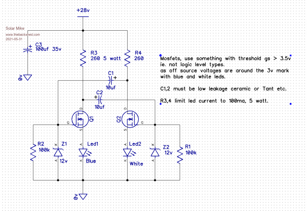 Cheers Mike Edited 2021-05-31 11:50 by Solar Mike |
||||
| bob.steel Senior Member Joined: 27/02/2020 Location: AustraliaPosts: 188 |
Thank You very much Mike. Ill let you know . Lights are 12/24 volts and run well on my 27volts solar supply so I guess I can skip the 12v zeners? Edited 2021-05-31 15:35 by bob.steel |
||||
| phil99 Guru Joined: 11/02/2018 Location: AustraliaPosts: 1776 |
The zenners are there to protect the gates. For most common MOSFETs the max allowed is 20V. |
||||
| Solar Mike Guru Joined: 08/02/2015 Location: New ZealandPosts: 1123 |
My understanding of your original spec was individual leds with 3 wires, now you are saying lights that run at 12 or 24v. The circuit outlined is for leds not higher voltage lamps with multiple leds inside them. If you want to use higher voltage groupings of leds then a different design will be required, normally blue and white leds have a voltage drop 2.6 - 3 volts odd. Skipping the zeners and the fets will blow up with too high a gate voltage. Cheers Mike |
||||
| bob.steel Senior Member Joined: 27/02/2020 Location: AustraliaPosts: 188 |
Oh OK Mike Ill try it that way. The lights are 12 0r 24 volt LED spotlights. 3 wires . At 27 volts they pull 55 mA on blue and 450 odd on the white light. The mosfets I want to use are any of IRF3205,IRFZ24N,IRFZ44Z as noted top of the circuit I posted. I have other choices up to about 90 volts and 90 odd amps I think My system is 27 volts and I want to plug them straight into the circuit . The circuit will be switched on by a day/night movement sensor also running at 27 volts and will flash each colour for one second each while current flows. I commonly use the big LED spotlight chips mounted on an alloy heatsink and needing about 30 volts to run .They pull about an amp at 27v. Not sure how the LEDs themselves are aligned . I didn't think that detailing the rest was necessary as these LED spotlights are quite common on ebay for cars and trucks. Good thing I came back for another look ,I was just about to start building the circuit. I'll build it and alter it later for more current. When I get it running properly I'll come back and do the parts list and URL's for the complete light and sensor so others can use it if they want . Been using them for about 5 years now. |
||||
| bob.steel Senior Member Joined: 27/02/2020 Location: AustraliaPosts: 188 |
Yeh I see that now . However it mentions +- 20 v so would that not be a 40 v useable range? |
||||
| Solar Mike Guru Joined: 08/02/2015 Location: New ZealandPosts: 1123 |
OK, so the lamps don't require any dropping resistors to run, they will connect direct to your 27v supply, with a common 0v connection. Thus high side switching is required, more difficult, the above circuit wont work for this. >> big LED spotlight chips mounted on an alloy heatsink and needing about 30 volts to run... These require a constant current source or limiting resistor, cannot connect these direct to a supply as will suffer from current runaway and blow up. See what I can do, will be more complicated... it always is. Cheers Mike |
||||
| bob.steel Senior Member Joined: 27/02/2020 Location: AustraliaPosts: 188 |
Well this blue white spotlight will take the place of the LED spotlights I use now . There is no current limiting required . You connect them straight to the 27 volts and they run nicely normally . I connect my lab supply at 30 volts ,fully open currentwise and they take 1 amp and under . This new light will take half of that and I have had it on the lab supply to test it . The blue only 55 mA. So there won't be any runaway on the spotlights! Appreciate the effort Mike This might help https://www.ebay.com.au/itm/183969526495 This is the light Edited 2021-05-31 19:55 by bob.steel |
||||
| Solar Mike Guru Joined: 08/02/2015 Location: New ZealandPosts: 1123 |
They look great, those spotlights have the limiting circuitry built in, you are good to go with those. I have some of the 20 watt led chips here, they take about 1 amp, but without current limiting draw exponential amounts of current as the voltage changes upwards. Cheers Mike |
||||
| bob.steel Senior Member Joined: 27/02/2020 Location: AustraliaPosts: 188 |
Thanks . So can I use your circuit above without the current limiting resistors R3 and R4 ? Is that what you are saying? |
||||
| Solar Mike Guru Joined: 08/02/2015 Location: New ZealandPosts: 1123 |
Correct, circuit will only work with low voltage single paired leds requiring limiting resistors. Will not work with your high voltage lamps. A simple cross coupled flip flop circuit will require PCh mosfets to work with your lamps. Or a more complex circuit arrangement to work with Nch. Think this will work, I don't normally use P-ch mosfets for anything, and the circuit is sort of upside down. 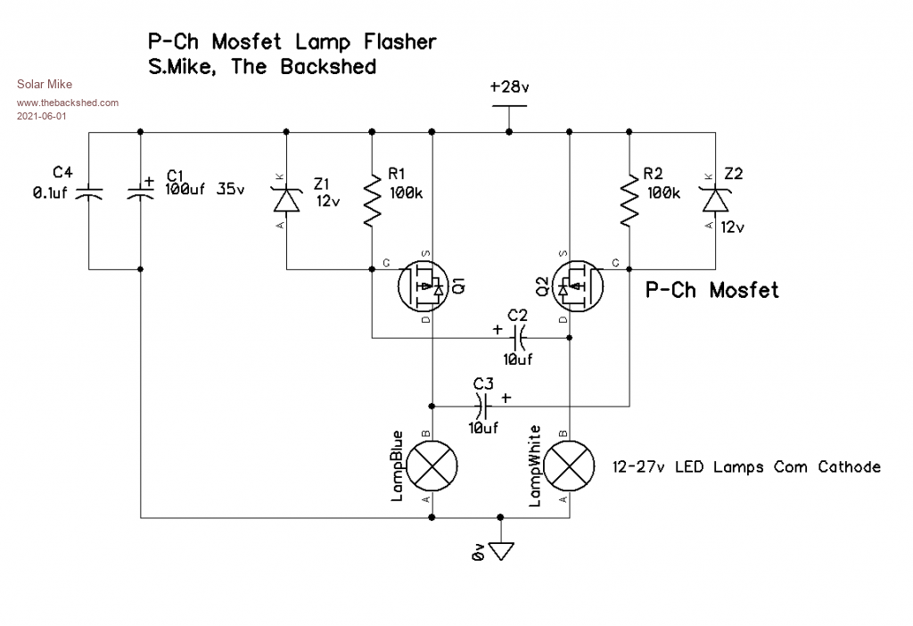 Cheers Mike Edited 2021-06-01 10:07 by Solar Mike |
||||
| bob.steel Senior Member Joined: 27/02/2020 Location: AustraliaPosts: 188 |
Yeah Mike ,but I don't have any P Channel Mosfets ,I don't use them ,and hundreds of N channel. That's why I was trying for an N cannel circuit. I will probably replace all my security lights with these if they look OK flashing . Thats say 20 atm . Edited 2021-06-01 12:29 by bob.steel |
||||
| bob.steel Senior Member Joined: 27/02/2020 Location: AustraliaPosts: 188 |
In case anyone is interested in building these security lights I use :- A small weatherproof box for the sensor. $3.50 A new sensor day/night/time adjustable They have changed it but this should be similar without the case $5 A spotlight of 100 watts 12/24volt.They change all the time like the one above $10 to $30 This all works on any voltage from about 6v to 30v. The new sensors are an improvement as I can flash a torch on then from 30 yards and they come on . They pick me up much further out and the time can be dropped to 13 seconds lowest which is enough for me . I used to have to have a day night lampost sensor and a movement sensor separate attached to each light. The spotlights outsides don't weather well but copper grease on the threads helps. I drill a hole in the box center ,remove the plastic covers and epoxy the Sensor unit to the back of the top . I solder wires to it so as not to use the round power connectors. Small wires ,max 1 amp current. I drill a bolt hole in the side to accomodate whatever light you choose . I end up with something like this:- 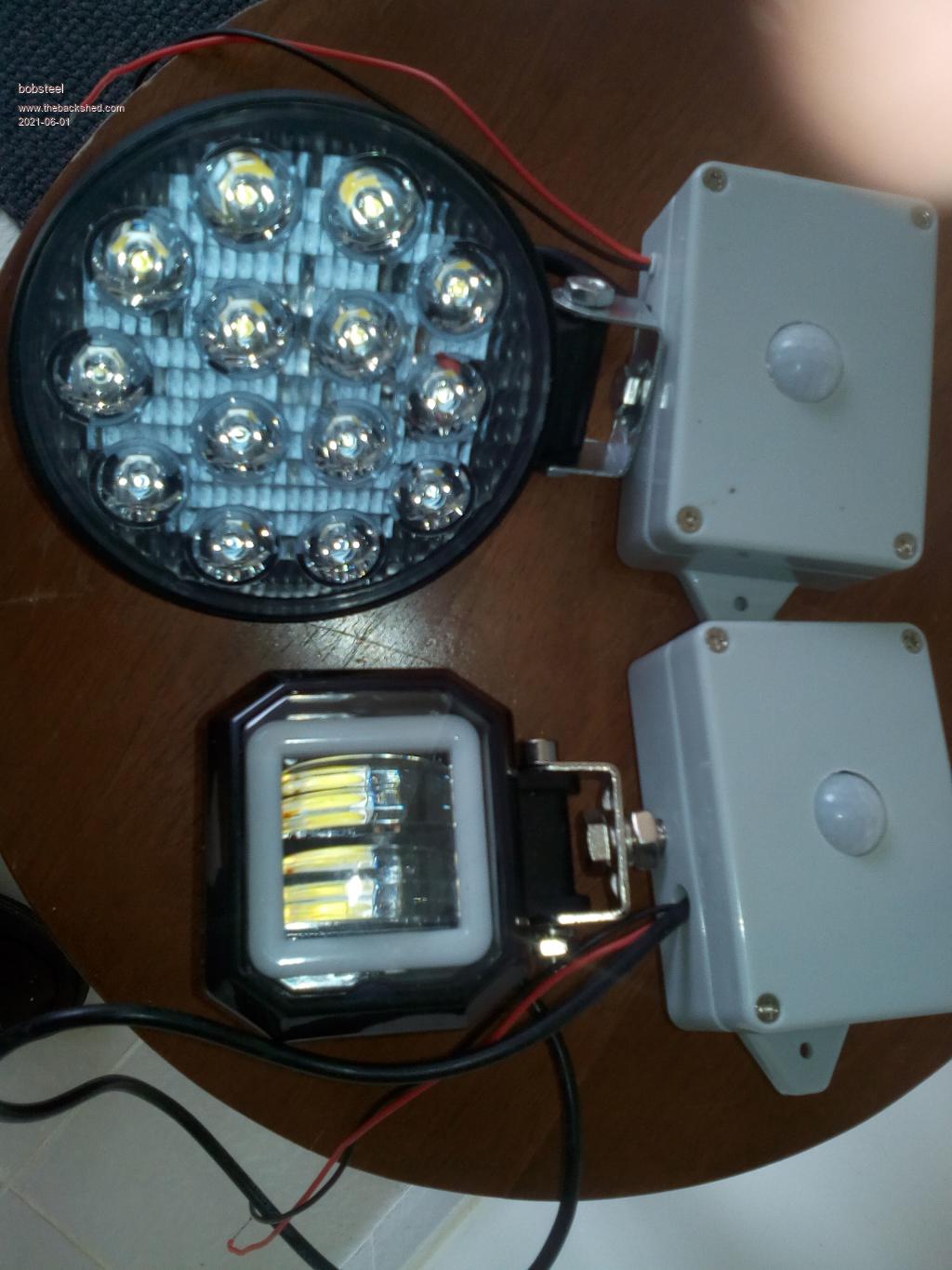 Edited 2021-06-01 13:22 by bob.steel |
||||
Grogster Admin Group Joined: 31/12/2012 Location: New ZealandPosts: 9059 |
About the only way I can see that you could use N-channel MOSFET's with these lights, is if you hack the lights to make them common anode(supply) instead of common cathode(ground) as they are now. That probably would not be easy or practical. Solar Mike's circuit is exactly how I would do it - high-side MOSFET switches for a common-ground load, low-side MOSFET switches for a common-supply load. You might just have to bite the bullet and buy some P-channel MOSFETS - unless you are prepared to hack and rewire all the lights to be common-anode.  Someone else might come up with something to make use of your N-channel MOSFETS, but I think it would be tricky. Smoke makes things work. When the smoke gets out, it stops! |
||||
| wiseguy Guru Joined: 21/06/2018 Location: AustraliaPosts: 993 |
Bob I did some doodling whilst on call waiting, this is untested but looks to me like it should work. I'm sure Mike Or Warp will help decide if it will work. Its a simple multivibrator driving the two FETs alternately. It bootstraps the gate voltage for the FET when they turn on to ensure they are fully enhanced for the "flash". When Q1 is on C1 charges via D1 and ZD1, When Q1 turns off the charge in C1 is presented to the Gate of Q3 via R1 which turns on, ZD1 now keeps Q3's Gate below 18V and the rail voltage at the Drain of the FETs is alternately applied to the 2 LEDs. R1 & R2 are also the pull up resistors for the multivibrator of Q1 & Q2. Dont know how Mike puts up nice schematics within the post I'll just link it to a pdf. I do hope it works - I also like to use up the stuff I've got lying around.... Schematic LED Flash.pdf Edited 2021-06-02 08:34 by wiseguy If at first you dont succeed, I suggest you avoid sky diving.... Cheers Mike |
||||
| bob.steel Senior Member Joined: 27/02/2020 Location: AustraliaPosts: 188 |
Thanks ,appreciate it . Looks like it uses trannys in place of normal PChannels to flashh then they control the Nchannels . Got to study that a bit 12 components up to 18 . Not a problem but Ive got to make up a board at some stage and I am useless with Kicad and eagle. Ah well ,time will tell |
||||
| wiseguy Guru Joined: 21/06/2018 Location: AustraliaPosts: 993 |
16 Parts if you dont count the 2 x LEDs and for the 6? extra components you get to use up your N channel FETs. The total component cost without the FETs is around 50c - $1. A circuit this simple would be a great opportunity to learn the art of schematic and pcb design, for very little risk or cost. Edited 2021-06-02 14:55 by wiseguy If at first you dont succeed, I suggest you avoid sky diving.... Cheers Mike |
||||
| Page 1 of 5 |
|||||
