
|
|
Forum Index : Microcontroller and PC projects : PicoMite Alpha Firmware
| Author | Message | ||||
disco4now Guru Joined: 18/12/2014 Location: AustraliaPosts: 1000 |
The pin functional designation is zero numbered. So I2C will use i2c0sda and I2C2 will use i2c1sda. A bit confusing at first look. COM1 will probably use UART0RX/UART0TX when it comes. COM2 will probably use UART1RX/UART1TX when it comes. Edited 2021-06-07 23:23 by disco4now Latest F4 Latest H7 FotS |
||||
| matherp Guru Joined: 11/12/2012 Location: United KingdomPosts: 10189 |
This one is a no win. The pins are labelled I2C0SDA, I2C0SCL, I2C1SDA and I2C1SCL However, all versions of MMBasic use I2C for the standard I2C channel (in this case I2C0) and I2C2 for the second channel (in this case I2C1) I could change it to I2C (implies 0) and I2C1 - thoughts ? |
||||
| lizby Guru Joined: 17/05/2016 Location: United StatesPosts: 3348 |
This works for me to flash LEDs on an MCP23017: ' MCP23017.bas const mcp23017 = &h20 ' A2, A1, A0, R/W all connected to 0V Const i2caddr=mcp23017 const IODIRA = &h00 ' Port A IO Direction register DEFAULT = I/P const IODIRB = &h01 ' Port B IO Direction register DEFAULT = I/P const IOCON = &h0A ' IO Expander config register - address &h0B accesses the same register const GPIOA = &h12 ' Port A General purpose register const GPIOB = &h13 ' Port B General Purpose register const OLATA = &h14 ' Port A latch register const OLATB = &h15 ' Port B latch register const GPUPB = &h0D ' Port B pull-up register SetPin 14,i2c1sda SetPin 15,i2c1scl I2C2 open 100, 1000 I2C2 WRITE MCP23017,0,2,IODIRA,0 ' set direction to output I2C2 WRITE MCP23017,0,2,IODIRB,0 ' set direction to output ' I2C2 WRITE MCP23017,0,2,GPUPB,&h3f ' set weak pullups on all except bits 6&7 do mcp17 loop sub mcp17 ' I2C2 WRITE MCP23017,0,2,IODIRA,0 ' set direction to output ' I2C2 WRITE MCP23017,0,2,IODIRB,0 ' set direction to output print "write to mcp23017" for i = 1 to 6 I2C2 Write MCP23017,0,2,OLATA,&b10101010 ' I2C2 Write MCP23017,0,2,OLATB,&b01010101 ' PAUSE 1000 I2C2 Write MCP23017,0,2,OLATA,&b01010101 ' I2C2 Write MCP23017,0,2,OLATB,&b10101010 ' PAUSE 1000 Next i I2C2 Write MCP23017,0,2,OLATA,0 ' turn all off I2C2 Write MCP23017,0,2,OLATB,0 ' turn all off pause 1000 end sub 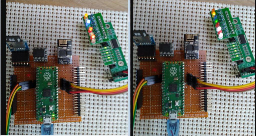 ~ Edited 2021-06-08 00:11 by lizby PicoMite, Armmite F4, SensorKits, MMBasic Hardware, Games, etc. on fruitoftheshed |
||||
| matherp Guru Joined: 11/12/2012 Location: United KingdomPosts: 10189 |
a20 again PicomiteV5.07.00a20.zip For some sort of consistency I've changed it to I2C for channel 0 (I2C0SDA,I2C0SCL) and I2C1 for channel 1 (I2C1SDA,I2C1SCL) Breaks my example and Lizby's test but just global replace I2C2 by I2C1 Note to Lizby: If you stored your program in flash then after changing the firmware the program will have edited itself - confused the f..k out of me until I realised it the displayed text is the token expansion  Edited 2021-06-08 00:21 by matherp |
||||
| Mixtel90 Guru Joined: 05/10/2019 Location: United KingdomPosts: 7821 |
I can't test this. I never could get a I2C 1602 LCD text display to work. lol I never had problems with them in parallel mode, but I don't have the magical touch for I2C. :) I like the idea of using I2C and I2C1 purely for compatibility in the MMBasic family. I assume it works with: SETPIN pin, I2C0, SDA SETPIN pin, I2C0, SCL I2C OPEN speed,timeout I2C WRITE addr, option, sendlen, senddata [,senddata ...] I2C READ addr, option, rcvlen, revbuf I2C CLOSE SETPIN pin, I2C1, SDA SETPIN pin, I2C1, SCL I2C1 OPEN speed,timeout I2C1 WRITE addr, option, sendlen, senddata [,senddata ...] I2C1 READ addr, option, rcvlen, revbuf I2C1 CLOSE Edited 2021-06-08 00:46 by Mixtel90 Mick Zilog Inside! nascom.info for Nascom & Gemini Preliminary MMBasic docs & my PCB designs |
||||
| lizby Guru Joined: 17/05/2016 Location: United StatesPosts: 3348 |
No problem. I2C1 works. PicoMite, Armmite F4, SensorKits, MMBasic Hardware, Games, etc. on fruitoftheshed |
||||
| matherp Guru Joined: 11/12/2012 Location: United KingdomPosts: 10189 |
spurious commas |
||||
| Mixtel90 Guru Joined: 05/10/2019 Location: United KingdomPosts: 7821 |
Thanks Peter. Just keeping my info updated in this case. :) Mick Zilog Inside! nascom.info for Nascom & Gemini Preliminary MMBasic docs & my PCB designs |
||||
| Mixtel90 Guru Joined: 05/10/2019 Location: United KingdomPosts: 7821 |
Yay! G8JCF did a Micromite library for this 1602 LCD display in 2014. Adding: SetPin 16, I2C0sda SetPin 17, I2C0scl has made it run on the Picomite. Note, folks, this is the first time I've had one of these running. :) I've not been able to move it onto different pins though, not even if they are specified alternatives for I2C0. Edit: Don't know what I was doing wrong, but I *can* move it to any I2C0 pins as expected. :) Edit: Updated & cleaned up. Now easy to see if you have the latest version. Picomite a9.zip . . Edited 2021-06-08 06:58 by Mixtel90 Mick Zilog Inside! nascom.info for Nascom & Gemini Preliminary MMBasic docs & my PCB designs |
||||
| matherp Guru Joined: 11/12/2012 Location: United KingdomPosts: 10189 |
a21 PicomiteV5.07.00a21.zip SPI now implemented SPI[1] OPEN freq, mode [,bits] bits per transfer can be between 4 and 16 e.g. connect pin 20 to pin 16 setpin 19,spi1sck setpin 20,spi1tx setpin 16,api1rx spi1 open 1000000,0 ? spi1(123) Use SPI1 command and function for SPI1aaa pins and SPI for spi0aaa pins Change to SDcard options to prepare for LCD panels and touch Use OPTION SYSTEM SPI CLKpin, MOSIpin, MISOpin to define the pins that will be used for the SDcard, the LCD panel and the touch controller Use OPTION SDCARD CSpin To define the pin that is used for the SDcard chip select Coming: OPTION LCDPANEL type, RSpin, RESETpin, LCDCSpin OPTION TOUCH IRQpin, CSpin Edited 2021-06-08 08:01 by matherp |
||||
palcal Guru Joined: 12/10/2011 Location: AustraliaPosts: 1982 |
@ Mixtel90 One typo in your doc. "It is better to be ignorant and ask a stupid question than to be plain Stupid and not ask at all" |
||||
| lizby Guru Joined: 17/05/2016 Location: United StatesPosts: 3348 |
a21 SD working: > OPTION SYSTEM SPI 4,5,6 > OPTION SDCARD 7 > files A:/ 1280 benchmark.bas 26240 ccpico.bas 11008 gui.bas 36 hello.bas 15104 loadtest.bas 20096 loadtest20.bas 24064 loadtest24.bas 27136 loadtest27.bas 1444 mcp23017.bas 4250 ta.bas 4700 tain.txt 1148 taout.txt 171 test1.bas 15 test2.bas 43 test3.bas 15 test4.bas 0 directories, 16 files PicoMite, Armmite F4, SensorKits, MMBasic Hardware, Games, etc. on fruitoftheshed |
||||
| led-bloon Senior Member Joined: 21/12/2014 Location: AustraliaPosts: 207 |
a21 fully loaded with SD card working great also. Another silly one! Incorrectly entered your small SPI test code: setpin 19,spi1clk setpin 19,spi1tx Got: Error: Invalid configuration <<<< Good setpin 20,spi1tx setpin 16,spi1rx spi1 open 1000000,0 Got: Error: Pin 99 is invalid <<<< oops! The SPI port was opened and working ok, however. Trying to open the port again would give the error "already open" which is correct. Another silly: > option list OPTION SYSTEM SPI GP2 ,GP3 ,GP4 The <space> char after the GPn and before the <comma> char Anyhow, thanks for all your hard work led Edit: added option list stuff Edited 2021-06-08 11:42 by led-bloon Miss you George |
||||
| Volhout Guru Joined: 05/03/2018 Location: NetherlandsPosts: 5027 |
Servo's work with a21. 'dual Servo sweep 'defines FREQ=50 'Hz PERIOD=1E6/FREQ 'us PWmin=800 'us PWmax=2200 'us DCmin=100*PWmin/PERIOD '% DCmax=100*PWmax/PERIOD '% ANmin=-90 'degrees ANmax=+90 'degrees 'calculates DCrange=DCmax-DCmin ANrange=ANmax-ANmin 'IO setup SetPin 1,pwm0a SetPin 2,pwm0b 'Sweep servo Do 'min->max sweep For angle = ANmin To ANmax Step 1 DC = DCmin + ((angle-ANmin)/ANrange)*DCrange PWM 0,FREQ,DC,DC Pause 20 Next angle 'max->min sweep For angle = ANmax To ANmin Step -1 DC = DCmin + ((angle-ANmin)/ANrange)*DCrange PWM 0,FREQ,DC,DC Pause 20 Next angle Loop End PicomiteVGA PETSCII ROBOTS |
||||
| CaptainBoing Guru Joined: 07/09/2016 Location: United KingdomPosts: 2170 |
Tx/Rx are confusing because they are subjective. SPI uses MOSI/MISO which leaves no doubt setpin 20,SPI1MOSI setpin 16,SPI1MISO is much better IMO I am glad the hard CS has been dispensed-with my 2p Edited 2021-06-08 19:04 by CaptainBoing |
||||
| matherp Guru Joined: 11/12/2012 Location: United KingdomPosts: 10189 |
You may be right but I am using Raspberry's own pin naming |
||||
| Mixtel90 Guru Joined: 05/10/2019 Location: United KingdomPosts: 7821 |
a21 - with a SD card now. :) Having a play with PWM on pin 24. Had to use SETPIN 24, PWM1A to get it to work - PWM0A didn't work (don't know if it should) pwm works, but can't set 0% (may not matter, but can set 100%. 0% *is* 100%!) PWM 1, OFF didn't work MM.INFO$(PIN 24) gives PWM3A PWM 3, off didn't seem to work but PWM 1, off then switched the LED off Pin 24 wasn't released. tried to release it with setpin, 24 off but got Error: Pin 24 is in use Should the pin have been released automatically? I've seen a diagram of which pins are which PWMs somewhere, but I can't find it now. That may reveal the PWM1/PWM3 issue. Edit: Found it on page 101 of "Getting started with MicroPython" It shows pin 24 as PWM_A[1] so I guess that's PWM1A so that bit's right. It ties in with Peter's chart too - which is where I should have looked...  Edited 2021-06-08 20:55 by Mixtel90 Mick Zilog Inside! nascom.info for Nascom & Gemini Preliminary MMBasic docs & my PCB designs |
||||
| matherp Guru Joined: 11/12/2012 Location: United KingdomPosts: 10189 |
a22 PicomiteV5.07.00a22.zip Minor fixes See table Fixed const struct s_PinDef PinDef[NBRPINS + 1]={ { 0, 99, "NULL", UNUSED ,99}, // pin 0 { 1, 0, "GP0 ", DIGITAL_IN | DIGITAL_OUT | UART0TX | SPI0RX | I2C0SDA | PWM0A,99}, // pin 0 { 2, 1, "GP1 ", DIGITAL_IN | DIGITAL_OUT | UART0RX | I2C0SCL | PWM0B ,99}, // pin 1 { 3, 99, "GND ", UNUSED ,99}, // pin 2 { 4, 2, "GP2 ", DIGITAL_IN | DIGITAL_OUT | SPI0SCK | I2C1SDA | PWM1A ,99}, // pin 3 { 5, 3, "GP3 ", DIGITAL_IN | DIGITAL_OUT | SPI0TX | I2C1SCL | PWM1B ,99}, // pin 4 { 6, 4, "GP4 ", DIGITAL_IN | DIGITAL_OUT | UART1TX | SPI0RX | I2C0SDA | PWM2A ,99}, // pin 5 { 7, 5, "GP5 ", DIGITAL_IN | DIGITAL_OUT | UART1RX | I2C0SCL | PWM2B ,99}, // pin 6 { 8, 99, "GND ", UNUSED ,99}, // pin 7 { 9, 6, "GP6 ", DIGITAL_IN | DIGITAL_OUT | SPI0SCK | I2C1SDA | PWM3A ,99}, // pin 8 { 10, 7, "GP7 ", DIGITAL_IN | DIGITAL_OUT | SPI0TX | I2C1SCL | EXT_PWM3B ,99}, // pin 9 { 11, 8, "GP8 ", DIGITAL_IN | DIGITAL_OUT | UART1TX | SPI1RX | I2C0SDA | PWM4A ,99}, // pin 10 { 12, 9, "GP9 ", DIGITAL_IN | DIGITAL_OUT | UART1RX | I2C0SCL | PWM4B ,99}, // pin 11 { 13, 99, "GND ", UNUSED ,99}, // pin 12 { 14, 10, "GP10", DIGITAL_IN | DIGITAL_OUT | SPI1SCK | I2C1SDA | PWM5A ,99}, // pin 13 { 15, 11, "GP11", DIGITAL_IN | DIGITAL_OUT | SPI1TX | I2C1SCL | PWM5B ,99}, // pin 14 { 16, 12, "GP12", DIGITAL_IN | DIGITAL_OUT | UART0TX | SPI1RX | I2C0SDA | PWM6A ,99}, // pin 15 { 17, 13, "GP13", DIGITAL_IN | DIGITAL_OUT | UART0RX | I2C0SCL | PWM6B ,99}, // pin 16 { 18, 99, "GND ", UNUSED ,99}, // pin 17 { 19, 14, "GP14", DIGITAL_IN | DIGITAL_OUT | SPI1SCK | I2C1SDA | PWM7A ,99}, // pin 18 { 20, 15, "GP15", DIGITAL_IN | DIGITAL_OUT | SPI1TX | I2C1SCL | PWM7B ,99}, // pin 19 { 21, 16, "GP16", DIGITAL_IN | DIGITAL_OUT | UART0TX | SPI0RX | I2C0SDA | PWM0A ,99}, // pin 21 { 22, 17, "GP17", DIGITAL_IN | DIGITAL_OUT | UART0RX | I2C0SCL | PWM0B ,99}, // pin 22 { 23, 99, "GND ", UNUSED ,99}, // pin 23 { 24, 18, "GP18", DIGITAL_IN | DIGITAL_OUT | SPI0SCK | I2C1SDA | PWM1A ,99}, // pin 24 { 25, 19, "GP19", DIGITAL_IN | DIGITAL_OUT | SPI0TX | I2C1SCL | PWM1B ,99}, // pin 25 { 26, 20, "GP20", DIGITAL_IN | DIGITAL_OUT | I2C0SDA | PWM2A ,99}, // pin 26 { 27, 21, "GP21", DIGITAL_IN | DIGITAL_OUT | I2C0SCL | PWM2B ,99}, // pin 27 { 28, 99, "GND ", UNUSED ,99}, // pin 28 { 29, 22, "GP22", DIGITAL_IN | DIGITAL_OUT | PWM3A ,99}, // pin 29 { 30, 99, "RUN ", UNUSED ,99}, // pin 30 { 31, 26, "GP26", DIGITAL_IN | DIGITAL_OUT | ANALOG_IN | I2C1SDA | PWM5A , 0 }, // pin 31 { 32, 27, "GP27", DIGITAL_IN | DIGITAL_OUT | ANALOG_IN | I2C1SCL | PWM5B , 1 }, // pin 32 { 33, 99, "AGND", UNUSED ,99}, // pin 33 { 34, 28, "GP28", DIGITAL_IN | DIGITAL_OUT | ANALOG_IN | PWM6A , 2 }, // pin 34 { 35, 99, "VREF", UNUSED ,99}, // pin 35 { 36, 99, "3V3 ", UNUSED ,99}, // pin 36 { 37, 99, "3V3E", UNUSED ,99}, // pin 37 { 38, 99, "GND ", UNUSED ,99}, // pin 38 { 39, 99, "VSYS", UNUSED ,99}, // pin 39 { 40, 99, "VBUS", UNUSED ,99}, // pin 40 { 41, 25, "GP25", DIGITAL_OUT | PWM4B ,99 }, // pin 41 }; |
||||
| Mixtel90 Guru Joined: 05/10/2019 Location: United KingdomPosts: 7821 |
a22 "Minor fixes" That's what we like to hear, Peter. lol Thanks, that seems to be working a treat now. Incidentally, I made a similar style SD breakout module to your own but omitted the supply rail cap. Power leads are pretty short so I figured I'd probably get away with it. It's working fine. :) Mick Zilog Inside! nascom.info for Nascom & Gemini Preliminary MMBasic docs & my PCB designs |
||||
| matherp Guru Joined: 11/12/2012 Location: United KingdomPosts: 10189 |
I'm now using this OPTION SDCARD GP15 OPTION SYSTEM SPI GP10,GP11,GP12 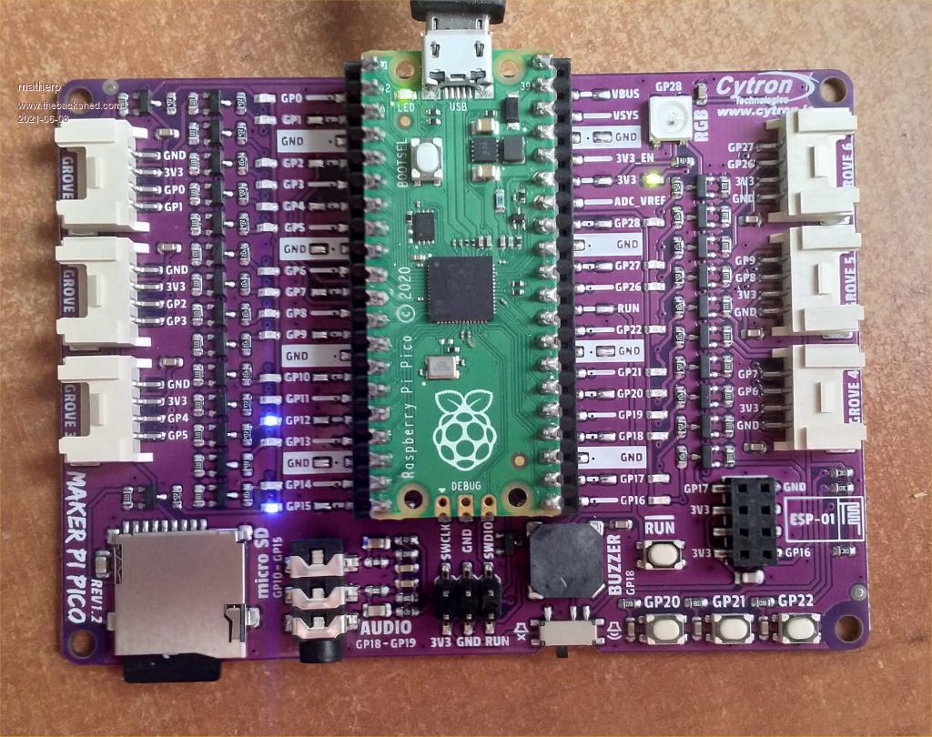 Edited 2021-06-08 23:04 by matherp |
||||
| The Back Shed's forum code is written, and hosted, in Australia. | © JAQ Software 2025 |
