
|
|
Forum Index : Microcontroller and PC projects : Relais controlled via Serial RS232
| Author | Message | ||||
| Mixtel90 Guru Joined: 05/10/2019 Location: United KingdomPosts: 7873 |
I said I was a bit evil... ;) TBH I wouldn't start with a chip that's just about obsolete. Microchip do far more capable chips now for about the same price. For something like this even the 32MX170 might be considered, even if it looks like overkill. Sometimes ease of use is far more important than the cost of the chip. Mick Zilog Inside! nascom.info for Nascom & Gemini Preliminary MMBasic docs & my PCB designs |
||||
| athlon1900 Regular Member Joined: 10/10/2019 Location: AustriaPosts: 49 |
You are right , the PIC16F84A is fully capable of running at 5V. Mixtel90 recognized it correctly  I wanted to be able to use it purely for hobby electronics without using a lot of components and be able to connect it directly to a mite, ESP01 or USB-serial converter that's why i'm using 3,3 Volts. For a "proper" RS-232 port with +/-12V you have to use a level-shifter (MAX232/3232 or identical ic's) . Yeah , the datasheet and the practice I have PIC16F8A-04/P in my treasure chest for about 20 years.  You are right , it should be a PIC16F84A-20 , but I can assure you that an PIC16F84A-04 runs at 8 mhz without any problems. The Components what i'm using are all in my treasure chest , i didn't want buy others.  Do you need more to control relays? I'm a bit confused.  You're right, I2C isn't mine. That would be a challenge for me.  Edited 2021-06-24 21:50 by athlon1900 |
||||
| Tinine Guru Joined: 30/03/2016 Location: United KingdomPosts: 1646 |
LOVE the MX170   There is a lot to be said for intelligent I/O expansion; the ability to Pulse an output, for example. Another is when you need to activate an output immediately after an input changes. Safety related: A "Start" signal for a machine, for me, isn't a simple contact closure with debounce, I have both a N/O AND a N/C and both need to change state. The I/O processor can figure out if there is a valid "Start" command and simply send a message to that effect. The serial communication protocol also needs to be robust and check-summed. For a wired system, I would always go with full duplex, multi-drop 422/485. The cost is negligible and it's very reassuring to have balanced line-drivers/receivers. Craig |
||||
| Tinine Guru Joined: 30/03/2016 Location: United KingdomPosts: 1646 |
Got some of these on order to test (see PDF). Also @matherp brought the TLP250H to our attention, some time ago. Came to order some and it seems to have been superseded by the the TLP350H. I have a handful and intend to punish the hell out of them on some hydraulic solenoid valves. High current source.pdf |
||||
| Tinine Guru Joined: 30/03/2016 Location: United KingdomPosts: 1646 |
Stuff I have from Aliexpress that I intend to stress-test 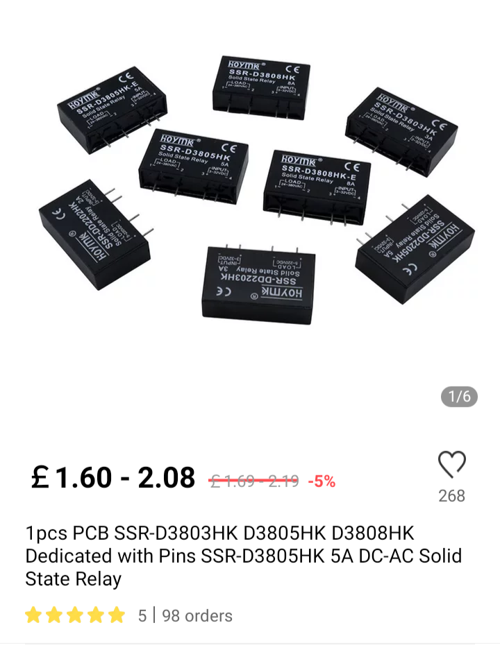   |
||||
| Mixtel90 Guru Joined: 05/10/2019 Location: United KingdomPosts: 7873 |
Fun toys! :) I like SSRs but there are some things they aren't good at - low voltage normally closed contacts for example. :) Agreed on the feedback, but for control you can detect the button close then check the contactor/delta contactor/VFD running signal is closed and (if possible) check the overload hasn't tripped. That tells you everything you need to know. You *never ever* do safety or essential process interlocks in software anyway. I'd like to see the PicoMite get native RS485 multi-drop support. It would make a great field module. I'm not so sure about CANbus. IIRC that's normally handled by dedicated chipsets so it would only be working with a controller or node chip anyway. Mick Zilog Inside! nascom.info for Nascom & Gemini Preliminary MMBasic docs & my PCB designs |
||||
| Tinine Guru Joined: 30/03/2016 Location: United KingdomPosts: 1646 |
Scenario: You provide a piece of machinery to your customer and it is equipped with all the approved, dual-redundant safety devices, including a wire-mesh cage. After some time, the production department gets frustrated with the increased cycle times caused by the fact that the operator has to open a gate and walk many more steps than when using a similar machine that isn't fitted with safety devices. Production instructs maintenance to simply jumper-out the dual redundant hard contacts, bypassing the safety system altogether. Operator gets hurt and contacts his lawyer and guess who ends up in court? Operator doesn't want to sue his employer because he wants to keep his job and so they go after the manufacturer of the machine. Manufacturer now has a problem because the customer is good for $6M/yr and the operator is looking for $500K. Do you kiss-off a $6M account by dragging the customer in to the court case? This happened to me in good ol' USA. Now, intelligent safety devices, sending coded messages and a constant heartbeat, cannot be bypassed. There are now wireless e-stop systems on the market, I think ABB were the first. For me, there is no reason why entire machines can't be controlled wirelessly. I intend to be doing this in the near future |
||||
| Mixtel90 Guru Joined: 05/10/2019 Location: United KingdomPosts: 7873 |
You've obviously not had to do a lot of installation in high RF areas. Radar pulses in your wiring can be a real pain! We used to do some airfield stuff where nothing short of hard-wired relays could be used - or would be accepted. Mind you, anyone even mentioning the possibility of bypassing safety devices would be out of the door there! It wasn't a case of safety, it's just that you couldn't trust any control or feedback signals to get through. Even cable screening makes a great antenna. :( Mick Zilog Inside! nascom.info for Nascom & Gemini Preliminary MMBasic docs & my PCB designs |
||||
| Tinine Guru Joined: 30/03/2016 Location: United KingdomPosts: 1646 |
In fact, the reason for being so confident is that I have done this before. Imagine a machine that makes 76mm diameter exhaust pipes from a flat coil of steel. The 3D shape is fully formed prior to being cut but how can the tube be rotated? It can't. Therefore the entire (huge) CNC bender has to be able to rotate, infinitely around the workpiece. The CNC bender has lots of incremental encoders and servo valves and not 1m away is a high frequency welder. The flat material is drawn through rollers, seam-welded and then feeds through the back of the continuously rotating bending machine. Hydraulic power was provided by a hydraulic slip ring but the big problem was the low-level signals. They had tried all kinds of methods including fingers in a mercury bath, custom designed optical couplers etc. I proposed a SBC on the rotating machine that would receive instructions and data from the main floor-based control. This was back in the CRT days and the screen image was all over the place, thanks to the high frequency welder but the wireless connection? Rock solid. |
||||
| Tinine Guru Joined: 30/03/2016 Location: United KingdomPosts: 1646 |
This is my 20-axis machine. The turret rotates infinitely and the eight (orange boxes) rotary servo axes are wirelessly (is that a word?) controlled. These are fuel injector tubes for Ford, Navistar and Siemens. 20 axis CNC Tube Bender Edited 2021-06-26 21:26 by Tinine |
||||
| Tinine Guru Joined: 30/03/2016 Location: United KingdomPosts: 1646 |
@Mixtel90 Just out of interest, who did you work for in the area? I was the first apprentice to emerge from Taylec (B&R Taylor)? |
||||
| Tinine Guru Joined: 30/03/2016 Location: United KingdomPosts: 1646 |
@Mixtel90 Just out of interest, who did you work for in the area? I was the first apprentice to emerge from Taylec (B&R Taylor)? |
||||
| Tinine Guru Joined: 30/03/2016 Location: United KingdomPosts: 1646 |
What's with the double posts |
||||
| Mixtel90 Guru Joined: 05/10/2019 Location: United KingdomPosts: 7873 |
Oh, that's a very nice machine. :) I was one of the control panel designers at Dewhursts - we dd a lot of work on a lot of sites, but the radar resistant stuff was for Warton. They didn't like electronic control and PLCs in many areas. I think that was sometimes because they wanted to be able to maintain all their gear themselves, even if the supplier disappeared. They didn't even like circuit breakers for computers - it was almost all Red Spot fuses. B&R Taylor. That rings some bells! :) They had a little drawing office off Chapel Brow at one time. I was living on Fleetwood street then and from our back bedroom we could see some poor soul working on a drawing board. lol Mick Zilog Inside! nascom.info for Nascom & Gemini Preliminary MMBasic docs & my PCB designs |
||||
| Tinine Guru Joined: 30/03/2016 Location: United KingdomPosts: 1646 |
As in regards to the 485 Enable? I seem to remember posting this some time ago: 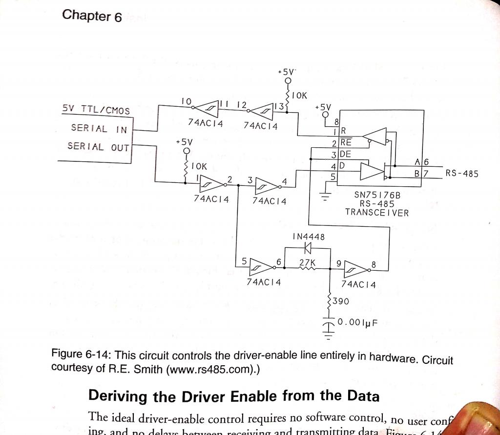  |
||||
| Mixtel90 Guru Joined: 05/10/2019 Location: United KingdomPosts: 7873 |
That's a very neat idea! I like that. :) Mick Zilog Inside! nascom.info for Nascom & Gemini Preliminary MMBasic docs & my PCB designs |
||||
| Volhout Guru Joined: 05/03/2018 Location: NetherlandsPosts: 5063 |
The timing in that hardware circuit works only at the baudrate it is designed for. And it may not work with slaves that respond too fast. Not saying this is no good, but it is designed for an application. PicomiteVGA PETSCII ROBOTS |
||||
| Mixtel90 Guru Joined: 05/10/2019 Location: United KingdomPosts: 7873 |
Cheaper on wire to switch it in software and use another pin. :) Mick Zilog Inside! nascom.info for Nascom & Gemini Preliminary MMBasic docs & my PCB designs |
||||
| Tinine Guru Joined: 30/03/2016 Location: United KingdomPosts: 1646 |
Were that an issue, it would be my opinion that the mistake was to go half-duplex. My own systems are multi-drop 485/422; the master has the Tx enabled permanently. All command/response and the slaves share the Rx line. |
||||
| The Back Shed's forum code is written, and hosted, in Australia. | © JAQ Software 2025 |
