
|
|
Forum Index : Microcontroller and PC projects : It works perfectly, but is it a horrific mess ?
| Page 1 of 2 |
|||||
| Author | Message | ||||
| thwill Guru Joined: 16/09/2019 Location: United KingdomPosts: 4379 |
Hi folks, As I indicate semi-frequently I'm a software guy not a hardware guy so haven't done much of this and I'd be interested in any feedback (I know that the some of the wires have bare metal tails that need clipping) or any discussion of prototyping techniques that it might prompt: 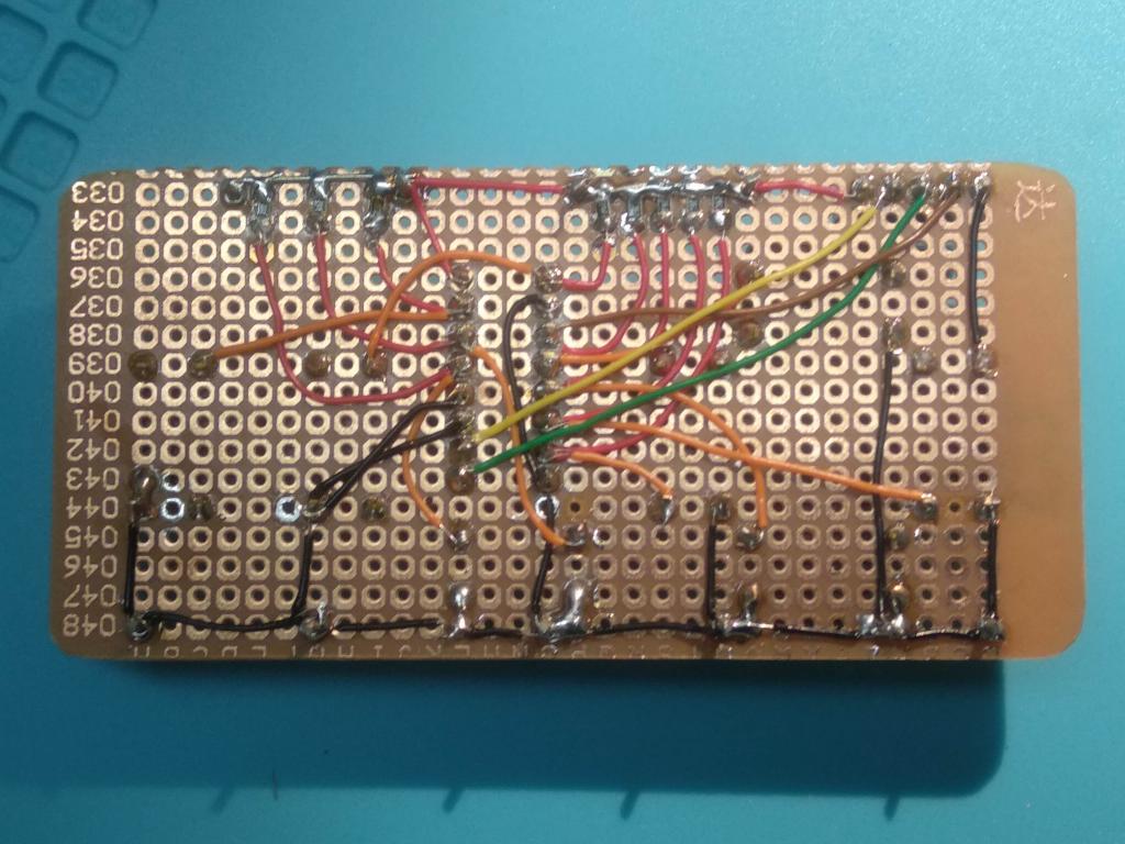 Just in case anyone wants to try and guess I won't say what it is yet other than it is for interfacing with the Picomite and there are no connections on the top surface, only components. Best wishes, Tom MMBasic for Linux, Game*Mite, CMM2 Welcome Tape, Creaky old text adventures |
||||
| hitsware2 Guru Joined: 03/08/2019 Location: United StatesPosts: 738 |
You tried your circuit on one of these first , right ? 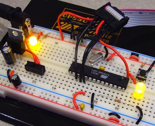 Edited 2021-06-16 09:32 by hitsware2 my site |
||||
Chopperp Guru Joined: 03/01/2018 Location: AustraliaPosts: 1126 |
Hi Tom, From my limited experience of using that type of prototyping board, it's not a bad effort. I don't like the stuff that much. I like at least some strips joined together. I prefer to use the Vero or Strip board as shown in an old board below I found in a drawer. I'm used to using this type & it is a bit more forgiving with the soldering & wiring. I also use a program called VeeCAD to help with layouts. The program can accommodate various types of prototyping boards of different sizes including the type hitsware2 has shown above. I know quite a few hobbyist etc go from the breadboard design straight to a PCB. We've all started from somewhere. If it works & reliable, it's good IMHO. 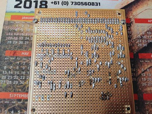 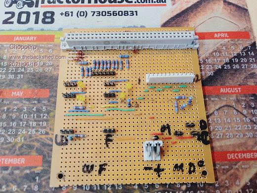 Brian ChopperP |
||||
| KeepIS Guru Joined: 13/10/2014 Location: AustraliaPosts: 2203 |
Nothing wrong with that work at all. I also agree with Veroboard, once you get good at layout it's one of the fastest and neatest ways to do a quick prototype, but like everything it depends on how you use it, some people hate Vero. NANO:Inverter V 8.2ks - Linux AvrDude GUI script V4.1 |
||||
| Volhout Guru Joined: 05/03/2018 Location: NetherlandsPosts: 5998 |
Hi thwill, It is a 16 pin dil chip with serial data in and parallel data out. I will do some datasheet checking, but my first guess is that it is a 4017, Ahhh, no, it is a keyboard Volhout Edited 2021-06-16 15:34 by Volhout PicomiteVGA PETSCII ROBOTS |
||||
| LeoNicolas Guru Joined: 07/10/2020 Location: CanadaPosts: 608 |
Nice job Tom Have you seen radio circuits from the '30s or '40s? Your board is pretty organized  The following image is from Mr Carson's Lab YouTube channel https://youtu.be/LC7OjuYAOQE 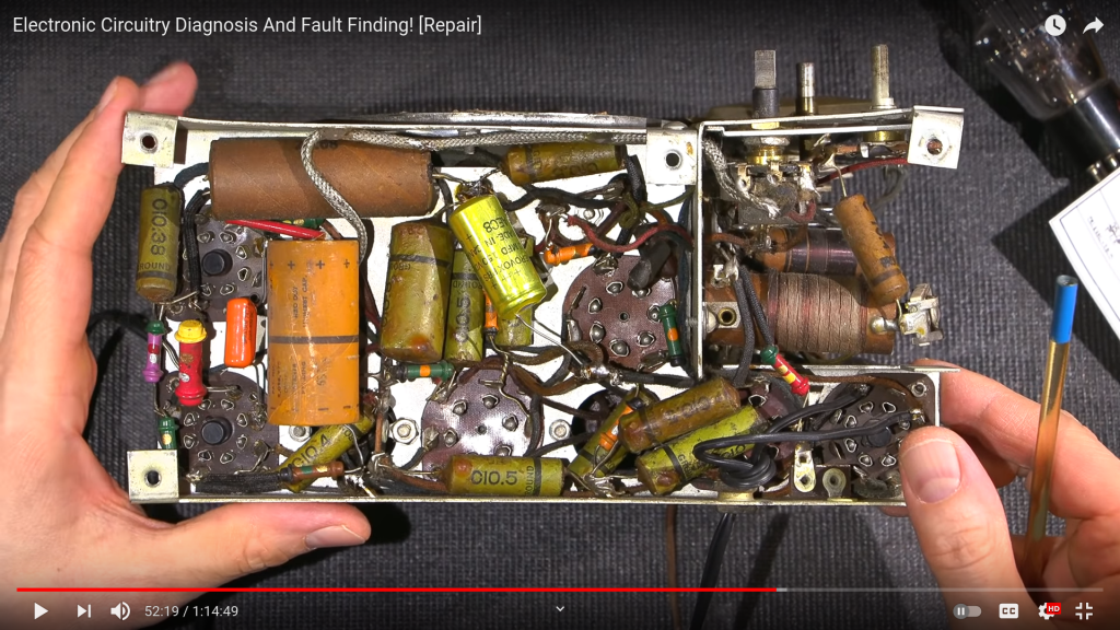 |
||||
| vegipete Guru Joined: 29/01/2013 Location: CanadaPosts: 1182 |
Pinout doesn't look right for a 4017. There appear to be pull-ups on pins 1,4,5,6,7,13,14,15 You might guess that pins 3,9,10 are clock, data and latch, in some order. Pin 2 could be reset or enable. Nothing obvious to me yet... Or it's not a chip at all but a connector. Good puzzle! Visit Vegipete's *Mite Library for cool programs. |
||||
| Volhout Guru Joined: 05/03/2018 Location: NetherlandsPosts: 5998 |
Hi Thwill, It is a HEF4014 (or 74HC4014) 8 bit serial IN shift register connected to 8 keys (pullup, switch to ground). The Shift-IN pin is grounded. Parallel load and shift clock are wired to the header, as is Q8 (the last flipflop output. As it is wired now, I expect the current consumption to be rather high, becuase you also grounded output pins Q6 (pin2) and Q7(PIN 12). Normally these are left not connected. Regards, Volhout PicomiteVGA PETSCII ROBOTS |
||||
| Mixtel90 Guru Joined: 05/10/2019 Location: United KingdomPosts: 8977 |
Oh yes! I've worked on stuff like that, Leo. :) Actually, I've built stuff not much better... lol My headphone amp has a couple of valves. 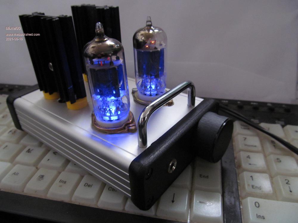 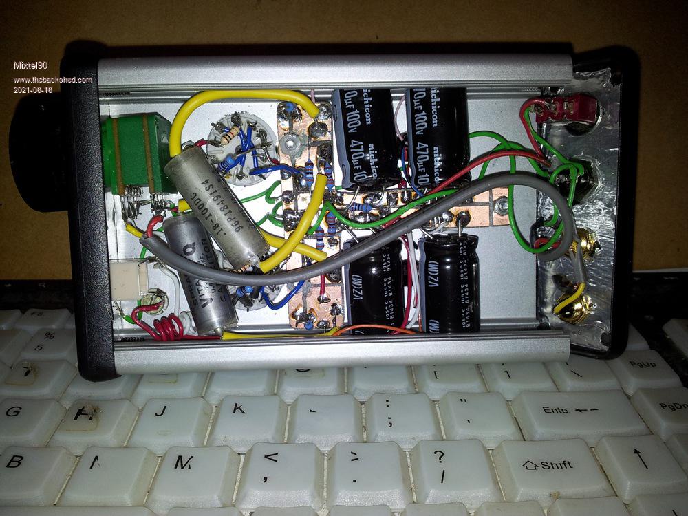 For the smaller stuff I usually use stripboard, but I'm using a padboard for a little auxiliary power supply at the moment - and not enjoying it very much. I think I'll make a PCB for the main board. It's more work but probably worth it in the end. Mick Zilog Inside! nascom.info for Nascom & Gemini Preliminary MMBasic docs & my PCB designs |
||||
| Volhout Guru Joined: 05/03/2018 Location: NetherlandsPosts: 5998 |
Aaaahhhhhh.... that hurts..... A set of ECC8x's directly driving headphones.... (12AX7 - ECC81 ?) These are pre-amplifer tubes that are designed for few mA and high impedance anode resitors (50k/100k)... The power is Okay (they will do 0.5 watt or so) but there is no output transformer to match the headset (32 ohm / 600 ohm ??). The build is nice. It is always hard to get a lot in a small space. But you managed to do so, and still have it "servicable". Making a PCB will not be easy, since the space is tight. Volhout Edited 2021-06-16 17:14 by Volhout PicomiteVGA PETSCII ROBOTS |
||||
| Mixtel90 Guru Joined: 05/10/2019 Location: United KingdomPosts: 8977 |
Nope. A pair of paralleled ECC82s as inputs, driving mosfet output stage in common source mode. The valve series heater is the source resistor for the mosfet and the headphone output is tapped off that junction. The mosfet is adjusted to pass 150mA. The beast runs from a 48v HP printer power supply. Pure inefficient class A. :) The "T" shaped PCB was the only sane way I could think of to fit the capacitors in the case. They were a little larger and the case a little smaller than I'd anticipated. lol Oh - I see your confusion... The PCB I'm considering making is for a bench power supply. Different project, but one that uses a MX170 and display for the controls. Which brings me nicely back onto topic. :) . . Edited 2021-06-16 17:23 by Mixtel90 Mick Zilog Inside! nascom.info for Nascom & Gemini Preliminary MMBasic docs & my PCB designs |
||||
| Chopperp Guru Joined: 03/01/2018 Location: AustraliaPosts: 1126 |
Reminds me of our Samsung Sound System. It has two "Tubes" glowing nicely through a window in the top of the chassis. It played up a few years ago so I took it in to get repaired under warranty. I asked the nice lady serving me about the two valves & she just laughed. "They're just dummies with backlit LED's " she said. I felt like a dummy myself. I had even read a review of the system with words including "the two tubes should give it a soft sound". Had him fooled too. Brian ChopperP |
||||
| Mixtel90 Guru Joined: 05/10/2019 Location: United KingdomPosts: 8977 |
These actually do something. The mosfet output stage, because of its arrangement, has a maximum gain of less than one. What it does do though, is convert the high impedance at the valve's anode to a low impedance for the headphones. The valve gives all the necessary gain in the circuit. Using the heater as the source resistor was a very clever idea by the designer as it dissipates about 1.9W and in this case that's not wasted heat. The original valves went very scarce - and were never really available in the UK anyway. A later version used the ECC82/12AU7 because it's reasonably linear with only a 48v supply. The "Starving Student" headphone amp: http://www.pmillett.com/starving.htm . . Edited 2021-06-16 18:08 by Mixtel90 Mick Zilog Inside! nascom.info for Nascom & Gemini Preliminary MMBasic docs & my PCB designs |
||||
| Chopperp Guru Joined: 03/01/2018 Location: AustraliaPosts: 1126 |
My first project as Tech in Training in 1970 was building (wiring up) a 5W valve amplifier (not to keep though). Can't remember if it was a Push-Pull or not. Slowly moved onto solid state stuff during my training. We at home used to have a Valve portable radio with a large 2.5V filament battery & 90V of HT batteries. Those were the days. Brian ChopperP |
||||
| thwill Guru Joined: 16/09/2019 Location: United KingdomPosts: 4379 |
Thank you to everyone for their comments. And the winner is @Volhout, specifically it is a CD4021BE - I hope one day I know enough to manage that trick: 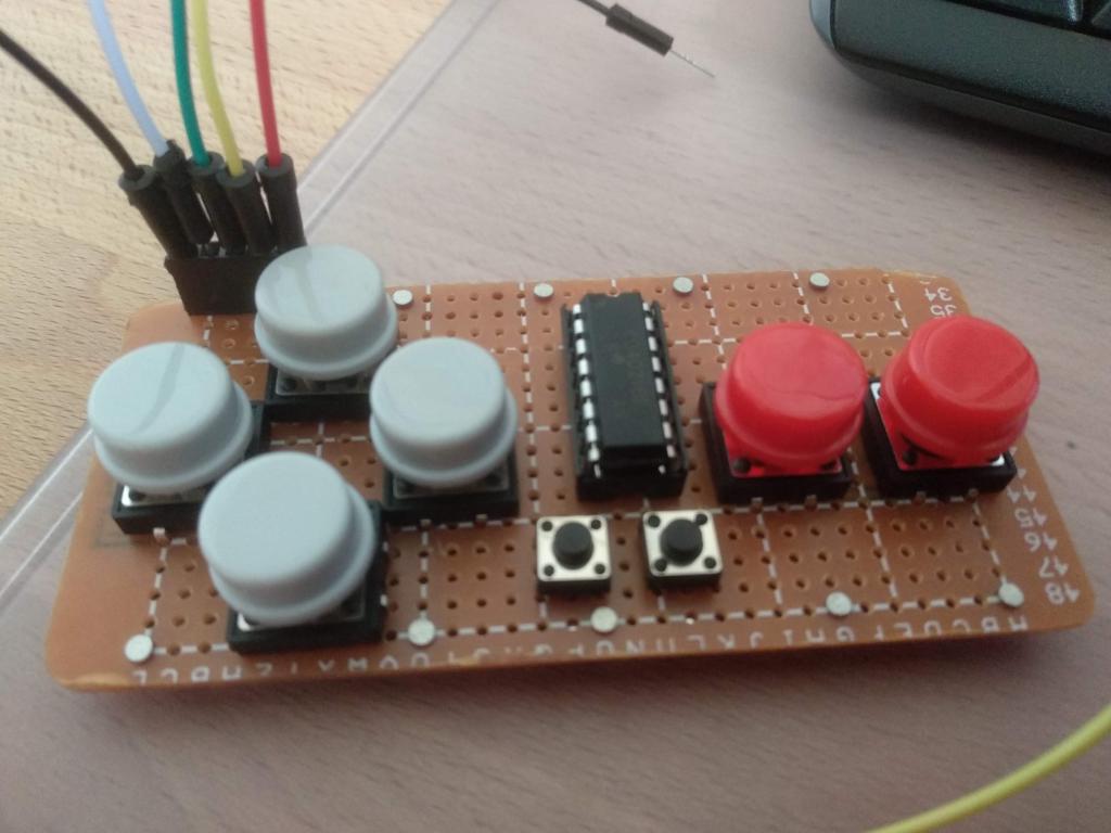 Thank you, that shows the danger of having only a little knowledge ... I'm sure I read that unused pins should be grounded, or is that a different logic family, perhaps 7400 ? Yes, my first prototype was on solderless breadboard, a bit unwieldy as a controller though  I do have a big piece of Veroboard but in my very limited experience I found it rather restrictive. I think my preference would be the perfboard with power-rails, but (a) I had this Chinese krud in stock, and (b) I wanted a very specific size. Thank you for the VeeCAD link, that looks very useful - even if it does mean more time infront of a screen. I went through several pages of paper perboard planner on this, and in the end winged much of it. I've not done any PCBs yet, though it is to come on this project. I suspect I would need the perfboard prototype to help me decide whether any given trace should be on the top or the bottom of the board ... plus I enjoyed the fine work ... though I'm not sure my eyes will be up to it for much longer. Best wishes, Tom MMBasic for Linux, Game*Mite, CMM2 Welcome Tape, Creaky old text adventures |
||||
| Mixtel90 Guru Joined: 05/10/2019 Location: United KingdomPosts: 8977 |
For many years I used AutoCAD so I got used to how it works. Of course, it's not something I can consider now that I've retired, but I found nanoCAD on the internet. It's free and very much like an older version of AutoCAD so it's ideal for me. I use it for all mechanical stuff, circuit diagrams and the simpler PCBs. It has limitations, but what do you want for free? I created a block of a lump of stripboard. I put that on a locked layer then draw stuff on it. https://nanocad.com/products/nanoCAD/download/ Mick Zilog Inside! nascom.info for Nascom & Gemini Preliminary MMBasic docs & my PCB designs |
||||
| Volhout Guru Joined: 05/03/2018 Location: NetherlandsPosts: 5998 |
@ THwill, Please be aware that these CD40xx chips are REALLY SLOW when running at 3.3V. The picomite may even in interpreted basic be to fast. If you plan to use SPI, be careful not to use a clock over 1MHz. 100kHz may be better even. (I know the datasheet says 6MHz, but that is running from 10Vdc....not 3.3V). Volhout PicomiteVGA PETSCII ROBOTS |
||||
| thwill Guru Joined: 16/09/2019 Location: United KingdomPosts: 4379 |
Thanks for the warning. For historical reasons, and because I didn't know any better I have a whole heap of ICs in this family. I suspect it won't be a problem at least for this controller as I am just bit-banging it and I believe I will only be clocking it in the 1kHz range. Best wishes, Tom MMBasic for Linux, Game*Mite, CMM2 Welcome Tape, Creaky old text adventures |
||||
| thwill Guru Joined: 16/09/2019 Location: United KingdomPosts: 4379 |
... the controller design is a clone of that used by the Nintendo Entertainment System (NES) https://www.allaboutcircuits.com/projects/nes-controller-interface-with-an-arduino-uno/ Best wishes, Tom MMBasic for Linux, Game*Mite, CMM2 Welcome Tape, Creaky old text adventures |
||||
| Volhout Guru Joined: 05/03/2018 Location: NetherlandsPosts: 5998 |
Hi Tom, I tested the CD4021 on a breadboard (actually a HEF4021, the Philips version), and have to conclude that you should not exceed 2MHz SPI clock. The setup: I connected a 74HC164 (shift out register) to SPI1 I connected the HEF4021 (shift in register) to SPI0 By doing this I can change the clocks of both SPI busses independently. I can run the clock on the 74HC164 up to 16MHz, but the HEF4021 starts generatng errors above 2MHz. For this test I connected the 8 output pins of the 74HC164 to the 8 input pins of the HEF4021 and compare if shift out data is identical to shift in data. This is the test program (no price for elegance or beauty): 'SPI test picomite hc164_clk%=16000000 CD4021_clk%=2000000 'configuration 74HC164 at SPI1 SetPin 19,spi1sck SetPin 20,spi1tx SetPin 16,spi1rx SPI1 open HC164_clk%,0,8 'configuration CD4021 at SPI2 SetPin 24,spi0sck SetPin 21,spi0rx SetPin 25,spi0tx SPI open CD4021_clk%,0,8 'load/shift pin 4021 SetPin 26,dout Pin(26)=1 'send random data to 74HC164 and read CD4021 response Print "Testing 74HC164 @ ";hc164_clk%; " Hz" Print "Testing CD4021 @ ";CD4021_clk%; " Hz" Print "press any key to stop" good=0:bad=0 Do snd=Int(256*Rnd()) a=SPI1(snd) Pin(26)=0 'shift get=SPI(0) Pin(26)=1 'load If snd=get Then ' Print "."; Inc good Else ' Print "*"; Inc bad EndIf ' Pause 50 Loop Until Inkey$<>"" Print Chr$(13);"good = ";good;" bad = ";bad PicomiteVGA PETSCII ROBOTS |
||||
| Page 1 of 2 |
|||||
| The Back Shed's forum code is written, and hosted, in Australia. | © JAQ Software 2026 |
