
|
|
Forum Index : Microcontroller and PC projects : Totally unrelated to anything....wake up clock
| Author | Message | ||||
| Volhout Guru Joined: 05/03/2018 Location: NetherlandsPosts: 5927 |
Wednesday mornign I realized my wake-up clock died (result: getting to work late....). Repair was out of the question (LED display, black goop blob on a single sided PCB). OK. I'll build one myself. After 2 evenings of hacking around, this morning I woke up to the sound of my own... 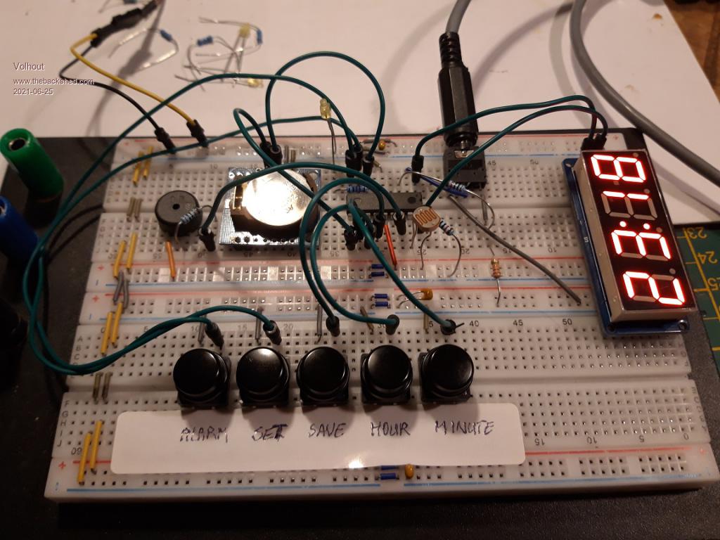 Now I still have to put it on stripboard and put it in a box.... Volhout PicomiteVGA PETSCII ROBOTS |
||||
CircuitGizmos Guru Joined: 08/09/2011 Location: United StatesPosts: 1427 |
Photo resistor for display dimming? Micromites and Maximites! - Beginning Maximite |
||||
| vegipete Guru Joined: 29/01/2013 Location: CanadaPosts: 1179 |
Nice. PIC16F??? with 2x I2C channels? Add some mains voltage so you really get blasted out of bed when you reach for the snooze button. :-) Visit Vegipete's *Mite Library for cool programs. |
||||
| Volhout Guru Joined: 05/03/2018 Location: NetherlandsPosts: 5927 |
A short update after 6 month of use. The clock works fine. The core is a PICAXE 18M2 running 4 tasks. The only problems with it where the real time clock module. The real time clock module is based on a DS1307 chip. This chip is old as coputers are. I remember my first XT computer had one in it, and it ran absolutely flawless. More accurate than my watch (Casio at that time). The DS1307 module I had had the wrong components in the battery charging circuit, (I posted about this before). And I discovered this after few month of use, also had a non-matching crystal soldered onto it. The DS1307 needs a crystal that is tuned for 12.5pF to be accurate. Well, the time on my wake up clock was off by 1-2 minutes per month. After investigation I needed to add around 10pF from each of the crystals pins to ground to tune it. One capacitor is a trimmer, so I could trim the clock within 0.1Hz (at 32.768kHz). It is absolutely accurate now. 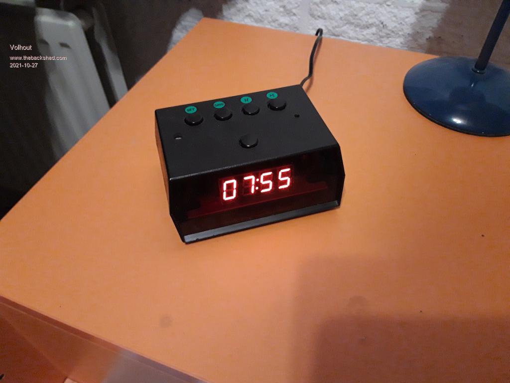 I know it is stupid to design a wake up clock you can buy for 2 dollar online, but it was satisfying.... The circuit is simple: a PICAXE 18M2, 5 buttons, a LED, a beeper, a RTC module, a TM1637 display module, and LDR (it adapst brightness depending on room lighting). All running from a phone charger. If you want to build it, the connections are in the code (pinning of the PICAXE). The code (4 tasks). ' TM1637_DS1307_tasks6.bas ' ------------------------------- alarm clock---------------------------------------- ' Version control ' tm1637_ds1307_tasks JAN 2019 initial version based on tasks ' tm1637_ds1307_tasks2,3,4 incremental releases with growing functionality ' tm1637_ds1307_tasks5 functional version FEB 2019, with open issue: alarm bell ' tm1637_ds1307_tasks6 2021 revival of project: format source, rebuild prototype ' Functional status ' displays time on TM1637 display, from reading real time clock DS1307 ' time can be set, alarm can be set ' alarm runs for 1 minute (the whole time the display digits are equal to alarm digits) ' elementary brightness control with LDR ' short manual: blinking colon: alarm on, solid colon, no alarm, cycle with alarm key ' cycle with set button through TIME and ALARM ' time: set with msb and lsb keys, then set (alarm) -or- save ' alarm: set with msb and lsb keys, then save ' alarm max 60 sec's, stop with alarm key ' 18M2 configuration ' display TM1637 connects to clk and dio pins (this is not real I2C) ' DS1307 connects to sda and scl (I2C) ' 5 control keys connect to individual IO lines to ground (internal pullups in port B) ' these 5 are: select, alarm, save, lsb, msb ' and LDR connected to ldr (C.0) measures daylight and controls display brightness ' best values LDR and pullup resistor to be determined ' other pins are used for debug led and beeper. #picaxe 18m2 ' 18M2 ' +----+ +----+ ' clk------1|C.2 C.1|18------dio ' RXD------2|C.3 C.0|17------ldr ' TXD------3|C.4 C.7|16------beeper ' ------4|C.5 C.6|15------ ' GND------5|0 Vcc|14------+5V ' led------6|B.0 B.7|13------save_key ' sda------7|B.1 B.6|12------msb_key ' sel_key--8|B.2 B.5|11------lsb_key ' alarmkey-9|B.3 B.4|10------scl ' +------------+ ; segment data for TM1637 ; ( 0 1 2 3 4 5 6 7 8 9 A b C d E F dash blank) DATA 0,($3f,$06,$5b,$4f,$66,$6d,$7d,$07,$7f,$6f,$77,$7c,$39,$5e,$79,$71,$40,$00) ' for TM1637 ' registers b0 and b1 are used as temp in the serial driver symbol dio = C.1 ' TM1637 data pin to 08m2 leg 6 symbol clk = C.2 ' TM1637 clock pin to 08m2 leg 5 symbol D3 = b2 symbol D2 = b3 ' for all 4 digits symbol D1 = b4 symbol D0 = b5 symbol change = b6 ' is there a change ? 0=no, 1=new, 2=new+colon symbol light = b7 ' adjustable brightness ' for ds1307, registers for the time and date symbol seconds = b8 symbol mins = b9 symbol hour = b10 symbol day = b11 symbol date = b12 symbol month = b13 symbol year = b14 symbol control = b15 symbol oldmins = b16 ' for the LDR symbol anain = C.0 ' pin C.0 as analog input symbol ldr = b17 ' value read from ADC for LDR (LDR to +vcc, 10k to GND) ' hmi (keys and LED) symbol led = B.0 ' debug led symbol sel = pinB.2 ' keys symbol save = pinB.7 symbol msb = pinB.6 symbol lsb = pinB.5 symbol mode = b18 ' edit mode 0=none ' alarm, registers for time and flags symbol alarm = pinB.3 ' button to stop the alarm symbol amins = b19 ' time symbol ahour = b20 symbol wake = b21 ' flag if alarm is on (1) or off (0) symbol bell = b22 ' counts to 60 as long as the bell rings symbol beeper = C.7 ' IO pin for the beeper (obsolete) 'this is the top level task ======================================================= start0: ' initialized the 18M2 then enter in an endless loop polling the keys ' in order to update the time, and start/stop the alarm. light = $89 ' set display brightness to dim oldmins = 0 ' initialize once the previous time dirsC= %10000110 dirsB= %00000001 pullup %11101100 ' enable pullups at B.7,B.6,B.5,B.3,B.2 mode = 0 ' start not in edit mode 'ahour = $06 ' default alarm time 06:55 'amins = $55 wake = 0 ' keep the alarm off=0, on=1 ' endless loop that scans the keys do pause 30 ' this pause ensures enough time for other tasks ' check for edit mode, we cycle through the 2 edit modes (edit1 = time, edit2 = alarm) ' only exit from edit mode is pressing the save key if sel=0 then ' enter edit mode from run mode inc mode ' edit time suspend 2 ' stop real time clock suspend 3 ' stop housekeeping : blinking colon and alarm check high LED ' debug - we are in menu mode do pause 30 loop until sel=1 end if ' check for alarm stop if alarm=0 then ' enter edit mode from run mode if bell=1 then bell=-60 ' silent for 60 times, enough to silence a minute => until next day else wake=1-wake ' invert alarm end if do pause 30 loop until alarm=1 end if ' here we are in edit mode 1, set time (hour and mins) if mode=1 then change=2 ' update display now in other task (needed here?) ' set hours, edit uses display memory D0...D3 if msb=0 then ' if msb pressed up the hours lsb inc D2 if D2=10 then ' if 10 then roll msb, and zero lsb inc D3:D2=0 end if if D2=4 and D3=2 then ' at 24, set to 00 D2=0:D3=0 end if change=2 ' update display now in other task do pause 30 loop until msb=1 ' wait until msb key released end if ' set minutes if lsb=0 then ' if lsb pressed up the minutes inc D0 if D0=10 then ' and roll over msb digit D0=0:inc D1 end if if D1=6 then ' at 60 return to 0 D1=0 end if change=2 ' update display now in other task do pause 30 loop until lsb=1 ' wait until key release end if hour=16*D3+D2 ' calculate new time, and update mins=16*D1+D0 ' counter memory end if ' here we are in edit mode 2, set alarm (hour and mins) ' during edit we copy alarm time to display if mode=>2 then ' copy alarm time to display, we edit display memory D3=ahour/16 D2=ahour&$0f D1=amins/16 D0=amins&$0f change=1 ' update display now in other task(needed?) ' edit display digits, alarm hours first if msb=0 then ' hours first inc D2 if D2=10 then ' roll over to hous msb inc D3:D2=0 end if if D2=4 and D3=2 then ' at 24 roll to 00 D2=0:D3=0 end if change=1 ' update display now in other task do pause 30 loop until msb=1 ' wait for key release end if ' edit the minutes of the alarm time if lsb=0 then ' at lsb ket press up minutes inc D0 if D0=10 then ' roll over to msb digit D0=0:inc D1 end if if D1=6 then ' at 60 roll back to 00 D1=0 end if change=1 ' update display now in other task do pause 30 loop until lsb=1 ' wait for key release end if ' copy display time back to alarm time ahour=16*D3+D2 amins=16*D1+D0 end if ' check if we leave edit mode if save=0 then ' exit edit mode ' update RTC with settings oldmins=60 ' i2cslave %11010000, i2cslow, i2cbyte writei2c 0,(seconds,mins,hour,day,date,month,year,control) writei2c 8,(ahour,amins) pause 100 ' go back to run mode mode=0 ' back to run mode restart 2 ' start real time clock restart 3 ' resume blinking colon and alarm check low LED ' debug do pause 30 loop until save=1 end if loop ' this task updates the display in case there is a change ========================= start1: do if change>0 then ' at any change update the display ' Set the brightness ($88 = on, $88 to $8F are the brightness levels) call i2CStart b0=light call i2CWrByte call i2CStop ' Enable sequential movement (from one digit to next) call i2CStart b0=$40 call i2CWrByte call i2CStop ' Move to first digit call i2CStart b0=$C0 call i2CWrByte ' First value read D3,b0 call i2CWrByte ' Second value read D2,b0 if change=2 then b0=b0+128 ' add 128 to turn on colon endif call i2CWrByte ' Third value read D1,b0 call i2CWrByte ' Fourth value read D0,b0 call i2CWrByte call i2CStop change=0 ' changes done end if loop ' -------------------------------------subroutines --------------------------- ' bit bang I2C routines used by TM1637 ignoring ACKN (not real I2C) i2CStart: high clk high dio low dio low clk return i2CStop: low clk low dio high clk high dio return ' Send a byte i2CWrByte: ' outpinC.1 = dio outpinC.1 = bit0:pulsout clk, 1 outpinC.1 = bit1:pulsout clk, 1 outpinC.1 = bit2:pulsout clk, 1 outpinC.1 = bit3:pulsout clk, 1 outpinC.1 = bit4:pulsout clk, 1 outpinC.1 = bit5:pulsout clk, 1 outpinC.1 = bit6:pulsout clk, 1 outpinC.1 = bit7:pulsout clk, 1 pulsout clk, 1 return ' ---------------------------------end subroutines --------------------------- ' this task reads the real time clock ============================================ start2: ' set DS1307 slave address i2cslave %11010000, i2cslow, i2cbyte ' Initialise the clock: option to do this only once, to set the initial time ' but in this clock we only use hours and minutes, so buttons to program is easy 'let day = $03 ; 03 Note all BCD format 'let year = $19 ; 03 Note all BCD format 'let month = $01 ; 12 Note all BCD format 'let date = $26 ; 25 Note all BCD format 'let hour = $17 ; 11 Note all BCD format 'let mins = $50 ; 59 Note all BCD format 'let seconds = $00 ; 00 Note all BCD format 'let control = %00010000 ; Enable output at 1Hz 'writei2c 0,(seconds,mins,hour,day,date,month,year,control) do ' Read the clock time readi2c 0,(seconds,mins,hour,day,date,month,year) 'actual RTC values readi2c 8,(ahour,amins) 'previously programmed alarm time ' check if different, so we can update display if oldmins<>mins then oldmins=mins D3=hour/16 D2=hour&$0f D1=mins/16 D0=mins&$0f change=1 ' update display now in other task endif pause 500 loop ' this task does all background tasks ========================================== start3: do ' dummy task to blink colon change=2 ' update display now in other task pause 500 ' this is the ON time o the blinking column ' check for alarms and execute, if alarm set colon blnks if wake=1 then change=1 ' update display now in other task pause 500 ' this is the OFF time of the blinking column ' only when alarm is on, hour is correct, minute is correct ring bell ' thus the alarm goes for 60 seconds if ahour=hour then if amins=mins then inc bell else bell=0 end if end if else bell=0 end if ' here the actual ringing takes place, either beeper or led drives the bell coil ' the display flashes or extra visual alarm if bell>=1 then high led ' make the display max brightness light = $8f change = 1 ' sound the alarm sound beeper,(120,10) pause 100 sound beeper,(120,10) pause 100 sound beeper,(120,10) ' make display dim light = $89 change = 1 low led else low led ' measure ambient light and adapt brightness ' LDR varies between $A0(light) and $0C (darkness) ' convert to $8F (bright) and $88 (dim) display readadc anain,LDR 'debug 'clip the ADC value for easy conversion if ldr>$7F then ldr=$7F end if ' conversion math (rough approximation) ldr=ldr/16 light=ldr+$88 ' to save battery current while debugging, overrule ADC value 'light = $89 end if loop ;================================================================================ Edited 2021-10-27 16:35 by Volhout PicomiteVGA PETSCII ROBOTS |
||||
| Volhout Guru Joined: 05/03/2018 Location: NetherlandsPosts: 5927 |
The code was nicely indented, but the copy and paste made a mess out of it. PicomiteVGA PETSCII ROBOTS |
||||
| Mixtel90 Guru Joined: 05/10/2019 Location: United KingdomPosts: 8904 |
That's really nice, Volhout. :) It has a really cool retro look - glad you stuck with a red 7-seg display. :) One of my digital clocks is one with a proper mains transformer (you can feel the weight). I suspect it's using mains frequency division as the frequency source as it never appears to drift at all when I compare it to a RF time signal clock. I know the RTC chips can be pretty accurate but I've rarely had one that didn't drift. Some of the little modules are pretty bad but you need a good frequency counter to set them up correctly. Edited 2021-10-27 16:56 by Mixtel90 Mick Zilog Inside! nascom.info for Nascom & Gemini Preliminary MMBasic docs & my PCB designs |
||||
| The Back Shed's forum code is written, and hosted, in Australia. | © JAQ Software 2026 |
