
|
|
Forum Index : Microcontroller and PC projects : Flash 3 common catode LED lamps.
| Author | Message | ||||
| Tinine Guru Joined: 30/03/2016 Location: United KingdomPosts: 1646 |
 I mentioned OPTO-22 SSR modules earlier which did an excellent job of protecting their fuses I mentioned OPTO-22 SSR modules earlier which did an excellent job of protecting their fuses |
||||
| Warpspeed Guru Joined: 09/08/2007 Location: AustraliaPosts: 4406 |
Haha, yes. You can get those "semiconductor fuses" but they are usually more expensive than what you are trying to protect. Cheers, ĀTony. |
||||
| phil99 Guru Joined: 11/02/2018 Location: AustraliaPosts: 1789 |
"You can get those "semiconductor fuses" but they are usually more expensive than what you are trying to protect." Yes I remember them, Geranium fuses that cost about $40 30 years ago, were installed in a forklift battery charger to protect a $5 bridge rectifier. The engineer that had us install them didn't understand why we were laughing. An over rated $10 rectifier would have lasted for ever. |
||||
| Mixtel90 Guru Joined: 05/10/2019 Location: United KingdomPosts: 5735 |
Lovely things, those semiconductor fuses. No use whatsoever without the impedance of the supply, a full surge spec of what they are protecting, resistance of the leads and the full blowing curves for the fuse. Guesswork results in a race as to which device protects the other. :) Mick Zilog Inside! nascom.info for Nascom & Gemini Preliminary MMBasic docs & my PCB designs |
||||
| PeterB Guru Joined: 05/02/2015 Location: AustraliaPosts: 639 |
Many years ago I was trying to build a cycloconverter using 36 SCRs connected every which way across the 3 phase mains. If 1 device got out of step it was a disaster. Those fast fuses were available but a visitor told me about the coffee jar fuse. A Nescafe jar containing the correct amount of water, 2 terminals in the lid , 2 bits of TCW running down into the water and a short length of 0076 connecting them. The idea was that excess current would vaporizer the water and so on. It was a bit unnerving with these 3 coffee jars jumping around but I never lost another scr. A bloke called Rissik (I think) managed it in Germany in the 30s using the technology available at the time. I gave up. Just reminiscing Peter |
||||
| Tinine Guru Joined: 30/03/2016 Location: United KingdomPosts: 1646 |
Hey I love to read about this stuff  |
||||
| CaptainBoing Guru Joined: 07/09/2016 Location: United KingdomPosts: 1985 |
+1 |
||||
| JohnS Guru Joined: 18/11/2011 Location: United KingdomPosts: 3661 |
+2 John |
||||
| Mixtel90 Guru Joined: 05/10/2019 Location: United KingdomPosts: 5735 |
+3.1415926 Mick Zilog Inside! nascom.info for Nascom & Gemini Preliminary MMBasic docs & my PCB designs |
||||
| Warpspeed Guru Joined: 09/08/2007 Location: AustraliaPosts: 4406 |
Great stuff Peter. Some of the old technology is absolutely fascinating, we are certainly living at a very interesting time in human history. Cheers, ĀTony. |
||||
| bob.steel Senior Member Joined: 27/02/2020 Location: AustraliaPosts: 188 |
OK for any followers that are interested in the circuit that works here it is below . 3 of these needed each light setup. Also I put the arduino ".ino" file for the control program to test it . Change it to any rate you want. Also a link to a video proof of the circuit.All LEDs flash but the camera angle does not get that . I came across and ordered some individual LED spotlights af slightly less power of about 50 watts . $6 each shown above ,nice flat construction. .These are interesting in that they have a mode that flashes itself and needs no more than a pulse I think to turn that mode on. I'm still experimenting with that . Forgive my complaints but it was taking far too long to get anywhere and everything posted as an answer was denegrated by somebody else and parts and powers etc were being screwed up by people who wanted to comment but did not have the facts right. Where is a learner to turn. When I design a board for production and get it back and prove it I will post the needed files too. Thank you 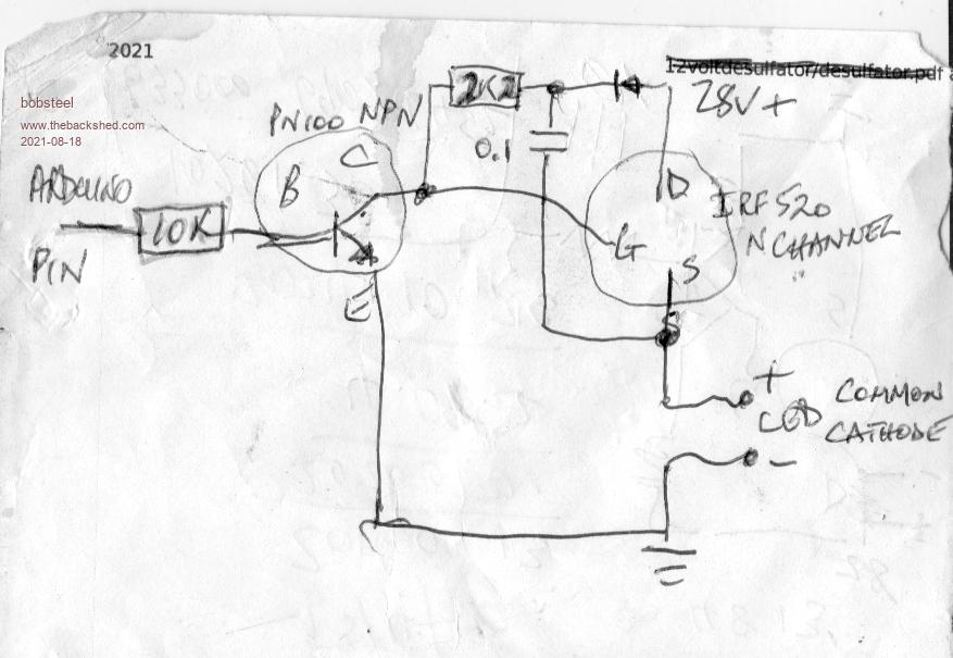 Mega file link LEDflashingLights.ino.zip Edited 2021-08-18 08:59 by bob.steel |
||||
| Warpspeed Guru Joined: 09/08/2007 Location: AustraliaPosts: 4406 |
Check your facts Bob. Find out what the maximum gate voltage rating of an IRF520 is. Are you feeling lucky ? Cheers, ĀTony. |
||||
| Tinine Guru Joined: 30/03/2016 Location: United KingdomPosts: 1646 |
Micrel (Microchip) 2981 Vs = 23.85 @1.08A Vout = 22.19 Using 4 of 8 channels Part 1 Part 2 Whoa, these videos are pretty big files  ...should've used lower res. ...should've used lower res.Running for a couple of hours now, still on 4 channels, each chip. Looking pretty good but I would probably add some form of heat-sink as Mick suggested. |
||||
| CaptainBoing Guru Joined: 07/09/2016 Location: United KingdomPosts: 1985 |
 ... good to go Edited 2021-08-18 16:50 by CaptainBoing |
||||
| Mixtel90 Guru Joined: 05/10/2019 Location: United KingdomPosts: 5735 |
Lovely! :) Those big resistors are supposed to be on a heatsink, of course. You have to de-rate them quite a way otherwise. I've fallen into that trap. lol The chips would almost certainly run cooler soldered to a pcb. I bet they'd be fine with 5 adjacent channels soldered down onto a half-decent area of copper. The old DIL audio amplifiers were very specific about that. 1.8W package dissipation isn't bad, although it's very high for those particular chips. The DMOS version would be well within their dissipation spec. @Bob Oh, it's a pity you didn't find those individual LEDs at the beginning! They would be dead easy to drive if wired common anode and put them in the drain side of your N-channel mosfets (ground the sources). All you need is a 100R gate resistor (and a turn-off resistor if you are fussy, say 100k). Mick Zilog Inside! nascom.info for Nascom & Gemini Preliminary MMBasic docs & my PCB designs |
||||
| Tinine Guru Joined: 30/03/2016 Location: United KingdomPosts: 1646 |
Yup, that's what the smell turned out to be....singed the darn table Still running happily. Been here all night, gonna run down to the local Wetherspoons for breaky and then I'll have a look for the TLP350H devices. They've been in my face for weeks but then I had a tidy up...Can't find a darned thing 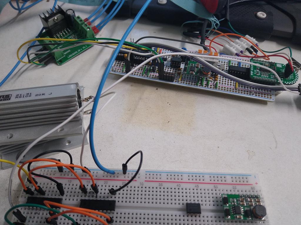 |
||||
| CaptainBoing Guru Joined: 07/09/2016 Location: United KingdomPosts: 1985 |
that's character!  |
||||
| Mixtel90 Guru Joined: 05/10/2019 Location: United KingdomPosts: 5735 |
LOL! "I love the smell of workbench in the morning!" Actually, I'm impressed by your Chinese breadboards. They seem to have handled 1A well. The maximum rating I've ever seen for this sort of board is 2A IIRC, and that was for an expensive make. Mick Zilog Inside! nascom.info for Nascom & Gemini Preliminary MMBasic docs & my PCB designs |
||||
| Volhout Guru Joined: 05/03/2018 Location: NetherlandsPosts: 3550 |
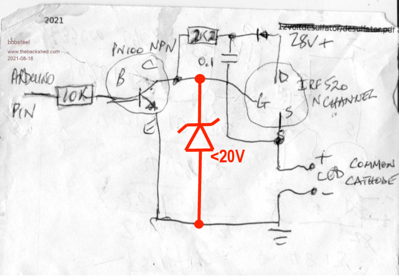
@ CaptaiBoing NO...That will never work. The zener must be attached between gate and source of the FET. Not to ground. @Bob.Steel NO... the capacitor you add will generate a nice positive drive to the gate of the FET, that is a "boost capacitor", as used in switching power supplies. But it only works as long as there is energy storage in the capacitor. For the values listed, that will be around 200us. So you need to drive the FET with 5kHz. But there is a reason why this does not work at all with LED's. LED's draw 900mA at 28V. But as soon as the output voltage gets lower (when turning off the LED) the LED diodes (yes, they are diodes) stop conducting. In essence, there is not enough current in to "charge" the boost capacitor again. Sorry, nice idea, but it does not work. If you want to use IRF520 FET's you NEED a constant boost voltage of 5V-10V on top of the 28V. That is what this whole long thread is about. Either buy common anode LED's, or drop the IRF520's (use something else). Volhout Edited 2021-08-18 19:24 by Volhout PicomiteVGA PETSCII ROBOTS |
||||
| Warpspeed Guru Joined: 09/08/2007 Location: AustraliaPosts: 4406 |
Yup. Cheers, ĀTony. |
||||
