
|
|
Forum Index : Microcontroller and PC projects : Flash 3 common catode LED lamps.
| Author | Message | ||||
| Turbo46 Guru Joined: 24/12/2017 Location: AustraliaPosts: 1639 |
Bob, A few things about Volhout's circuit: - It is for a P channel MOSFET and not suitable for your device. - Only 2 output circuits are shown, you would need a third. - Yes, F4000 is a fuse. OUT VCC is really the 28 volt supply input. - OUT 2 and OUT 3 are from the microprocessor. - Ignore LEDOUT 2 and 3, they would be for indicator LEDs - The zener diode D4010 restricts the gate voltage swing to 28 to 12 volts. -The 12VOLT-PMOS A means that the zener is shared between output circuit 1 and 2 (and output circuit 3 if you add one). - Diodes D4002 and D4003 would be suppression diodes for driving inductive loads. If you REALLY want to use your devices then you will need to use a circuit like that in the Captain's link or provide some kind of auxiliary supply voltage such as a battery or an isolated DC to DC converter to provide a gate voltage higher than the 28 volts supply. Electrons flow from negative to positive while current 'flows' from positive to negative.  Bill Keep safe. Live long and prosper. |
||||
| bob.steel Senior Member Joined: 27/02/2020 Location: AustraliaPosts: 188 |
I see .It'll come to me .Thanks What I want to do is turn these 3 (three) LED spotlights on in the fashion of a white light on for a longer while perhaps drawing 900 mA and then all off for half a second and then 4 pulses of power through the blue lamp drawing 100 mA all off again and then 4 pulses through the red LED drawing 100 mA then off and repeating all. My program atm is attached showing timing delays but its got to be adjusted for the third lamp. Adjusting delays and flashes is fairly simple and the only place I'm stuck is driving the mosfets or whatever to turn the lights on at full power and get a clean and separated cut off. At this point I'm just looking for a way to do that using whatever I need . I now have N channel and P channel mosfets ,plenty of transistors ,some relays and the obligatory 78012 ,9 and 5 plus quite an assortment of bits Ive even moved the bench to make room and tidy up LEDflashingLights.ino.zip  Edited 2021-07-22 15:34 by bob.steel |
||||
| Turbo46 Guru Joined: 24/12/2017 Location: AustraliaPosts: 1639 |
900mA at 28 volts is a lot of power! Is that correct? You can sort out the timing using normal LEDs with current limiting resistors. But then you need to decide which method you want to use to drive the higher powered LEDs. - Relays (click/clacks) - Volhout's circuit - Captain's link or a variation using an extra supply - Transistor circuit Someone here can help you once you decide. Bill Edit: Or you may find a suitable module on line. Edited 2021-07-22 16:01 by Turbo46 Keep safe. Live long and prosper. |
||||
| CaptainBoing Guru Joined: 07/09/2016 Location: United KingdomPosts: 2170 |
Welcome. You can see clearly from that, that current into the gate of a (MOS)FET is tantamount to zero (otherwise that charge would bleed away very quickly) - they are charge (voltage) controlled devices due to their insulated gate. So many times I see switching circuits using MOSFETS with current limiting resistors in the gate drive when there really is no need. It does no harm, but unless there are other considerations it is a waste. You effectively have a multi-MegOhm resistor (probably 50 or more on common devices) because of the gate insulation so no current flows anyway. Some specialist devices can be several GigaOhms e.g. those used on industrial motor drives - like trains etc. but they are often quite exotic in other ways. Although you are "new" to them, it will "click" with you and barring a few exceptions you'll be using MOSFETs for every DC power switching task. If you use ones with suitably low RDSon and switch them fast enough, you may not even need to put them on heatsinks. My heated build plate has 4.4A being PWMed at 2.5KHz and the MOSFET involved is standing in free air without a hint of warmth. Slow rise/fall times will push the MOSFET up and down it's curve and RDSon can become significant (well, you want it to go from infinite to zero and back so I guess it must follow that curve ). *Always* wear a good anti-stat strap when handling/touching - the 4KV required to stick a balloon to the wall will do your gate no favours! *Always* wear a good anti-stat strap when handling/touching - the 4KV required to stick a balloon to the wall will do your gate no favours! experiment loads and have fun. Edited 2021-07-22 17:47 by CaptainBoing |
||||
| Mixtel90 Guru Joined: 05/10/2019 Location: United KingdomPosts: 7858 |
Nobody has said "SSR" yet. So I will. :) Probably too expensive an option, but small DC ones will switch direct from a microcontroller and handle the voltage and current easily. A 4-channel 200VDC 5A module from China is 13.27UKP on ebay. "Click/clacks"!  - they work though, and we aren't talking PO3000 types here. lol - they work though, and we aren't talking PO3000 types here. lolDepending on location the noise might be completely inaudible anyway, especially if they are inside a box. Cap'n - the gate resistor isn't a current limiting resistor. It would be useless for that as the gate draws no current and the value is too low (<1k). It's for parasitic damping - to stop the HF "ringing" if the gate lead has any length. Generally, the longer the lead the worse the ringing gets, and anything over a few mm starts to count. The lead has inductance and the gate has capacitance so there's an LC circuit. Without it you run the chance of the mosfet oscillating at HF, especially in the non-linear areas of it's transconductance curve. The result is a hot mosfet. The resistor (and it has to be mounted as close as possible to the mosfet or it doesn't work) costs nothing and saves hours of headaches. :) Edited 2021-07-22 17:35 by Mixtel90 Mick Zilog Inside! nascom.info for Nascom & Gemini Preliminary MMBasic docs & my PCB designs |
||||
| CaptainBoing Guru Joined: 07/09/2016 Location: United KingdomPosts: 2170 |
good point and well made. I've never had a problem with it even with a couple of metres being driven directly from a low impedance source (a PWM pin in the case of the vid, you can see I have 10cm of wire and that is before the cable to the control unit is attached), but I had forgotten ringing suppression at such high resistance/capacitance as a result of the insulation, so good point to raise. I am not an "analogue man" so i never use FETs other than to switch power and they are always driven from a good strong (and fast) point. Edited 2021-07-22 18:34 by CaptainBoing |
||||
| Mixtel90 Guru Joined: 05/10/2019 Location: United KingdomPosts: 7858 |
It's one of those nasty things where you can put a scope on the gate and that makes the oscillation stop so you can't see a problem. :( Put the same probe on the drain and it's back... Hours of fun. :) Very often you'll have no problem at all without a resistor. It depends on the external inductance, the gate capacitance, any external capacitance, the speed of the mosfet, its slope, its bias point on the slope and the phase of the moon (!). It's very cheap insurance though, especially if you like to build on strip board. Creates havoc in audio output stages. :( Edited 2021-07-22 21:31 by Mixtel90 Mick Zilog Inside! nascom.info for Nascom & Gemini Preliminary MMBasic docs & my PCB designs |
||||
| Volhout Guru Joined: 05/03/2018 Location: NetherlandsPosts: 5056 |
The gate resitor is essential, but if your driver is a microprocessor pin, then there is already impedance in the io pin. Between 15 an 50 ohms generally. Captain: if you havent seen it wirh long wires and a low impedance driver, you probably havent looked close enough. The oscillation onky happens during the switching fron On to Off and back. It stops when the drive level settles. But during the transition the FET can dissipate lots of power, and can evenvdestroy the driver circuit. B.t.w low impedance gate drivers deliver 1A or more fir fast transitions in switchmode powersupplies an PWM motor drivers. PicomiteVGA PETSCII ROBOTS |
||||
| CaptainBoing Guru Joined: 07/09/2016 Location: United KingdomPosts: 2170 |
 you can bet I will be now. I have a good candidate on my bench that gets a 2.5KHz PWM signal straight from a micromite pin. I should see it on there. It hasn't got a great lump of wire between the pin and the gate but it doesn't have a resistor either. Probably the only time I will ever use my ancient HP high impedance active probe - hopefully high enough so as not to affect the hooting. you can bet I will be now. I have a good candidate on my bench that gets a 2.5KHz PWM signal straight from a micromite pin. I should see it on there. It hasn't got a great lump of wire between the pin and the gate but it doesn't have a resistor either. Probably the only time I will ever use my ancient HP high impedance active probe - hopefully high enough so as not to affect the hooting. |
||||
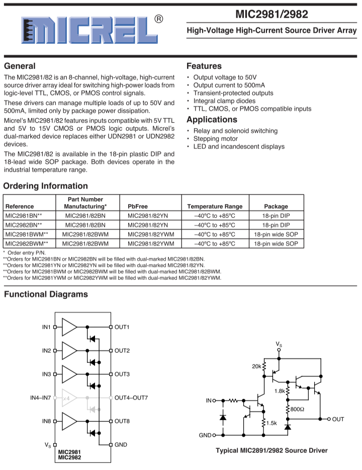
| Turbo46 Guru Joined: 24/12/2017 Location: AustraliaPosts: 1639 |
Bob, this might help. Bill Keep safe. Live long and prosper. |
||||
| lizby Guru Joined: 17/05/2016 Location: United StatesPosts: 3358 |
Informative article. I was surprised that they used the IRF540 for a high-side switch as well as a low-side switch. I'm far from experienced, but I thought there were much better parts for high-side switching. Also surprised that they didn't at least provide examples of "logic-level" mosfets which might be more suited to (some) microprocessor applications. PicoMite, Armmite F4, SensorKits, MMBasic Hardware, Games, etc. on fruitoftheshed |
||||
| Mixtel90 Guru Joined: 05/10/2019 Location: United KingdomPosts: 7858 |
Very good article, thanks lizby. The problem with the IRF540 is the usual - it needs fairly high gate drive to get anywhere. It's fine for low side driving at suitable supply voltages, but not for high side. It's quite an old device now and doesn't have terribly good characteristics by modern standards. N-channel isn't the right thing to use for high side switching (unless you are working with "inverted" supply rails with +ve to ground). However, N-channel is cheap and easy to fabricate for high power handling so you can get some *really big* N-channel mosfets. P-channel is the way to go for high side, but is far less easy to get and much more expensive as the power handling goes up. In Bob's case it's worth forgetting the IRF540 . It's way too big for what he needs and he's getting lumbered with the poor characteristics of a big device. He only needs a 2A device at maximum (if he really needs 900mA for white), the IRF540 is 20A plus. He'd be far better with something like the IRFI9610G, which is a P-MOS 200V 2A rated device. It's only 1.62UKP at RS, so it must be cheaper elsewhere. Rds is still a bit high so it would probably still need a heatsink. There are better. Mick Zilog Inside! nascom.info for Nascom & Gemini Preliminary MMBasic docs & my PCB designs |
||||
| Turbo46 Guru Joined: 24/12/2017 Location: AustraliaPosts: 1639 |
I only gave the reference for the information not to recommend the IRF540. Please note also that the article is 12 years old. Bill Keep safe. Live long and prosper. |
||||
| PeterB Guru Joined: 05/02/2015 Location: AustraliaPosts: 655 |
G'Day All. I'm with Bill. use a transistor up the top but make it a Darlington eg BD682. An NPN or FET could be used down the bottom but I think a transistor would be easiest. That's my two bobs worth.  Peter |
||||
| Tinine Guru Joined: 30/03/2016 Location: United KingdomPosts: 1646 |
 |
||||
| PeterB Guru Joined: 05/02/2015 Location: AustraliaPosts: 655 |
G'Day Tinine et al That is a bit light on for current but other than that it comes down to cost / convenience / availability / personal preference / etc. Peter And just to make it perfect, use a 4N25 etc on the input. P Edited 2021-07-24 20:21 by PeterB |
||||
| Solar Mike Guru Joined: 08/02/2015 Location: New ZealandPosts: 1162 |
You can parallel the inputs\\outputs for extra current. AliExpress Mike Edited 2021-07-24 21:23 by Solar Mike |
||||
| PeterB Guru Joined: 05/02/2015 Location: AustraliaPosts: 655 |
G'Day Mike. Yes you can but I have always been a bit nervous of connecting things in parallel because you can never be sure how the current will share unless you install an R in each leg and determining the value leads to insanity.  I do think using an opto-coupler is a good idea when connecting micros to the outside world. Peter |
||||
| Tinine Guru Joined: 30/03/2016 Location: United KingdomPosts: 1646 |
Hi Peter, It's common practice to parallel the channels of these devices; it all boils down to the total dissipation. I would probably use 4 channels for the 900mA and just because they are available, 2 channels for each of the 100mA loads. Bearing in mind, also that; these are flashing lights and so, presumably, 50% duty cycle? If opto is a a requirement then there is the TLP350H which will accomplish everything (2A). 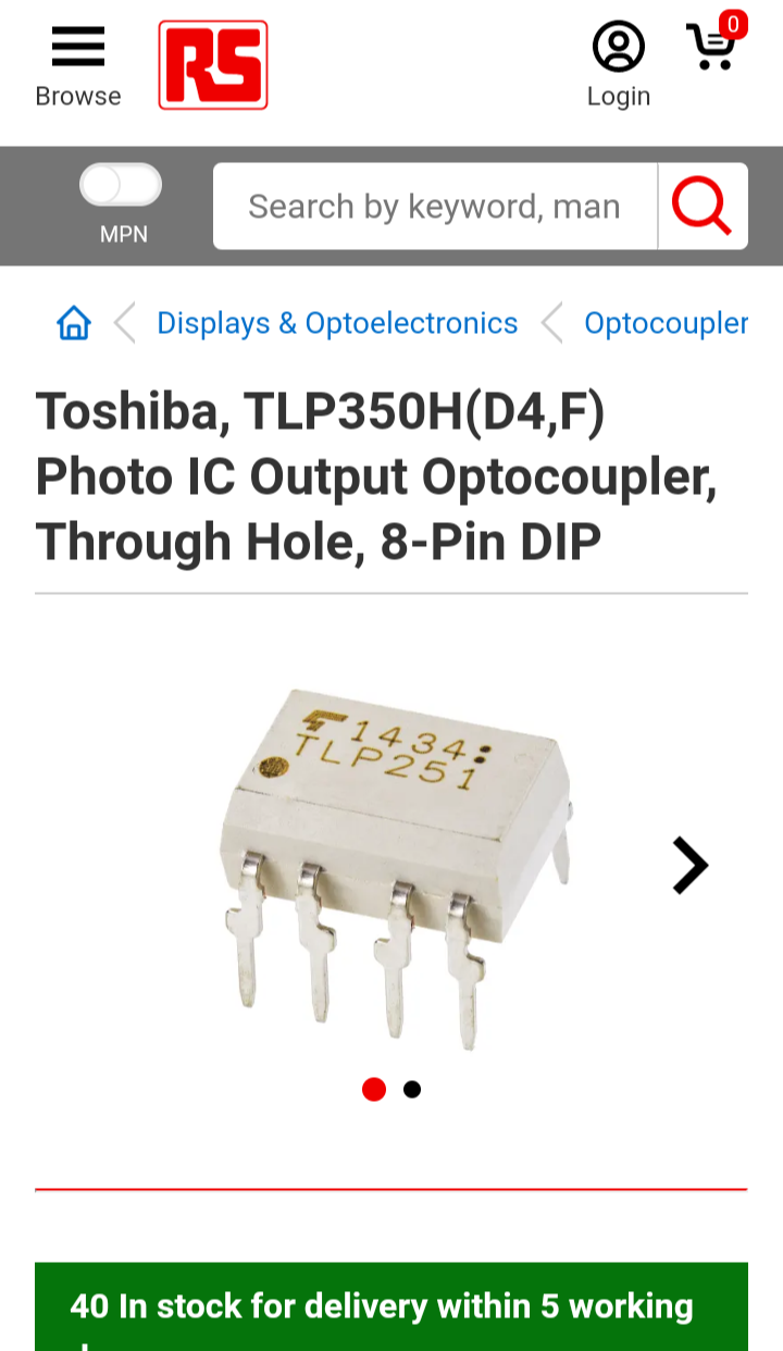 Edited 2021-07-24 22:46 by Tinine |
||||
| bob.steel Senior Member Joined: 27/02/2020 Location: AustraliaPosts: 188 |
I ordered a 4 channel one to check them out $9 AUD about 4 pounds UKP. I also ordered a 4 chanel relay board to try @ $5 AUD . 2 UKP On the SSD it shows 4, the input control signal voltage: (the state of the 0-1.5V low level relay ON) (the state of the 2.5-5V high level relay OFF) So I assume to turn the LED on I take the pin low? then leave the pin high till the next cycle. Would that be wasteful of power? |
||||
| The Back Shed's forum code is written, and hosted, in Australia. | © JAQ Software 2025 |
