
|
|
Forum Index : Microcontroller and PC projects : Pi Pico Security Alarm Driver
| Author | Message | ||||
| Solar Mike Guru Joined: 08/02/2015 Location: New ZealandPosts: 1211 |
I'm extending our security system to include a remote alarm driver that can be linked to the existing system or used as a stand alone alarm unit. Some of the noise makers used to wake the dead are sirens and large truck horns; these draw upwards of 30 odd amps off a localized 12v battery, the existing system wont really handle this unless I used heavy duty relays; so I thought an upgrade is in order. The truck horns driver will melt if run too long, so have to be switched on\off to limit heat build up. Some of the LED lamps will be flashed at a suitable confusing 10 - 13 Hz rate; thus requiring high power mosfet switches. Included is a simple PWM battery charger to keep the 12 volt LA. battery topped up. Will use a Pi Pico cpu module (u-Python) to run the system. Here is progress to date: 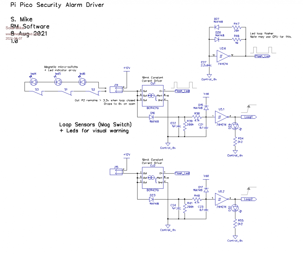 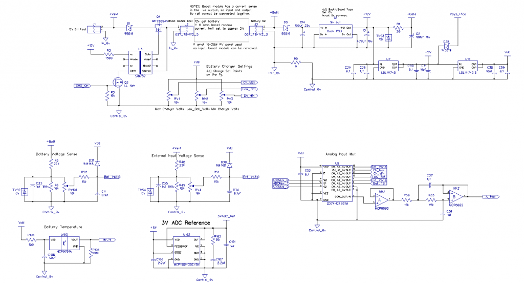 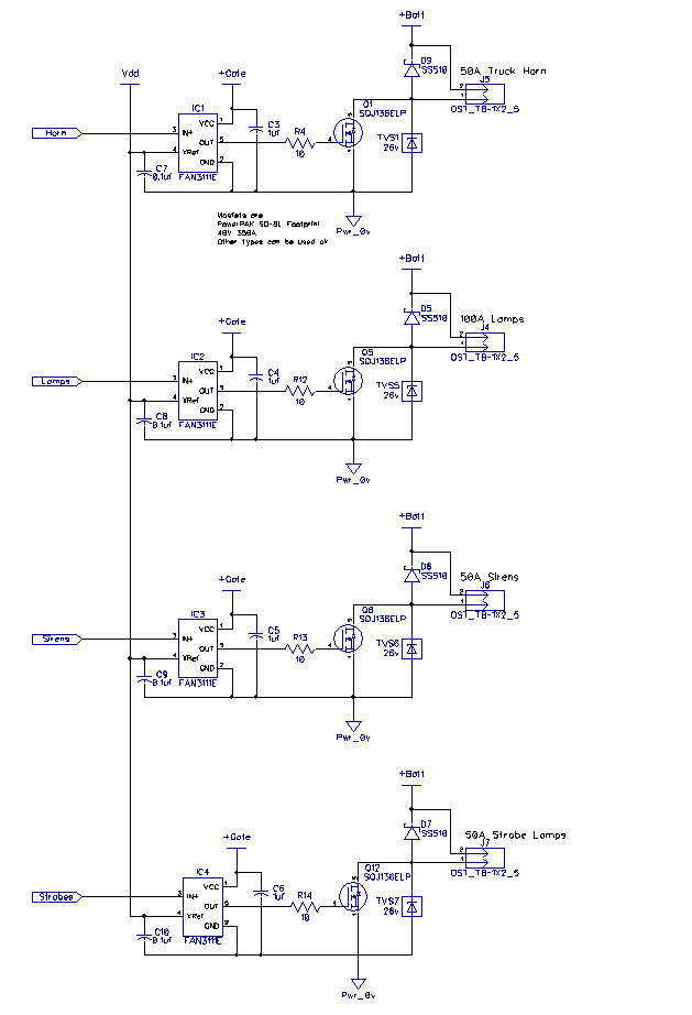 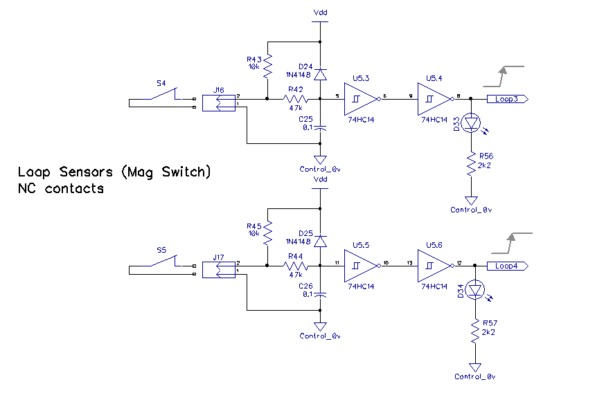 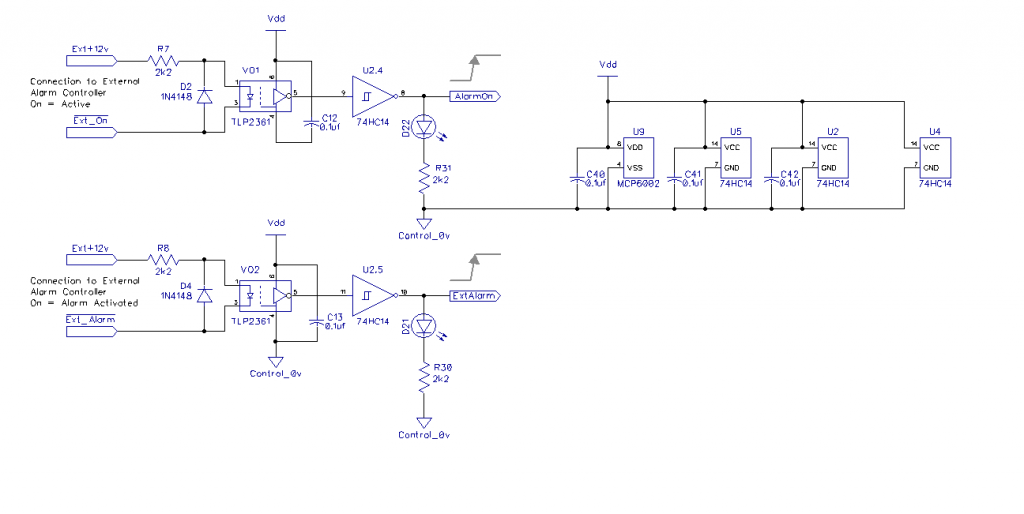 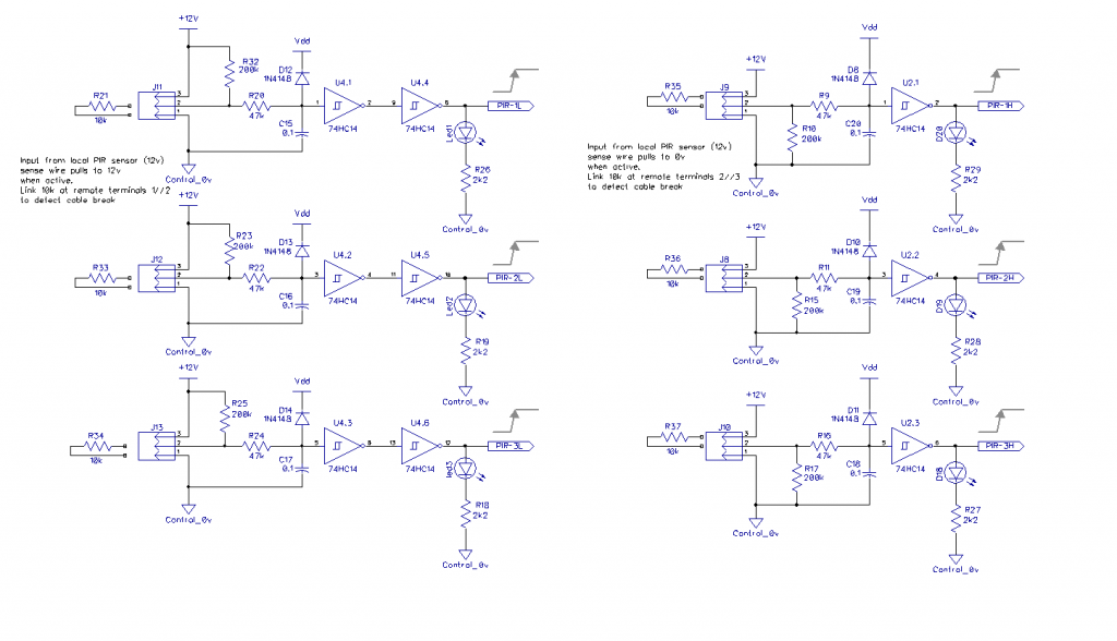 Cheers Mike |
||||
| Solar Mike Guru Joined: 08/02/2015 Location: New ZealandPosts: 1211 |
Have made some changes in the design, decided to use both digital (74HC251D) and analog multiplexers (CD74HC4051) to connect the cpu to various zone sensors and alarm outputs. Semi static relay and Led outputs are connected via High power serial shift registers, type NPIC6C596A-Q100. Schematic below: 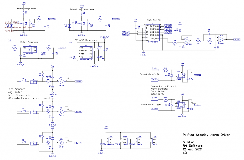 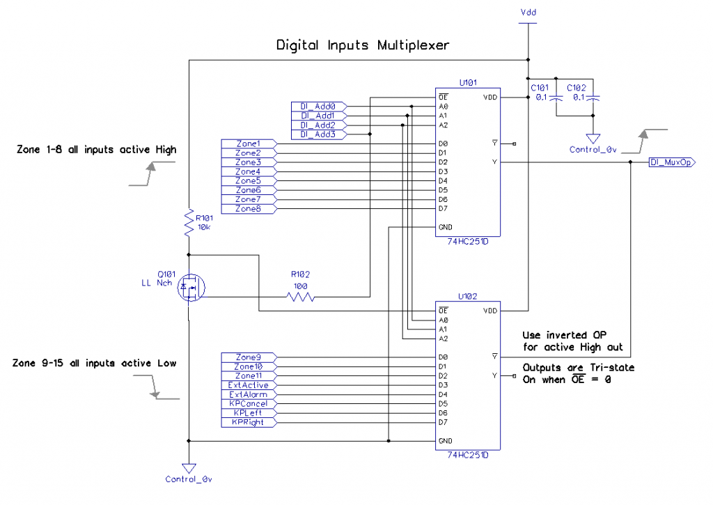 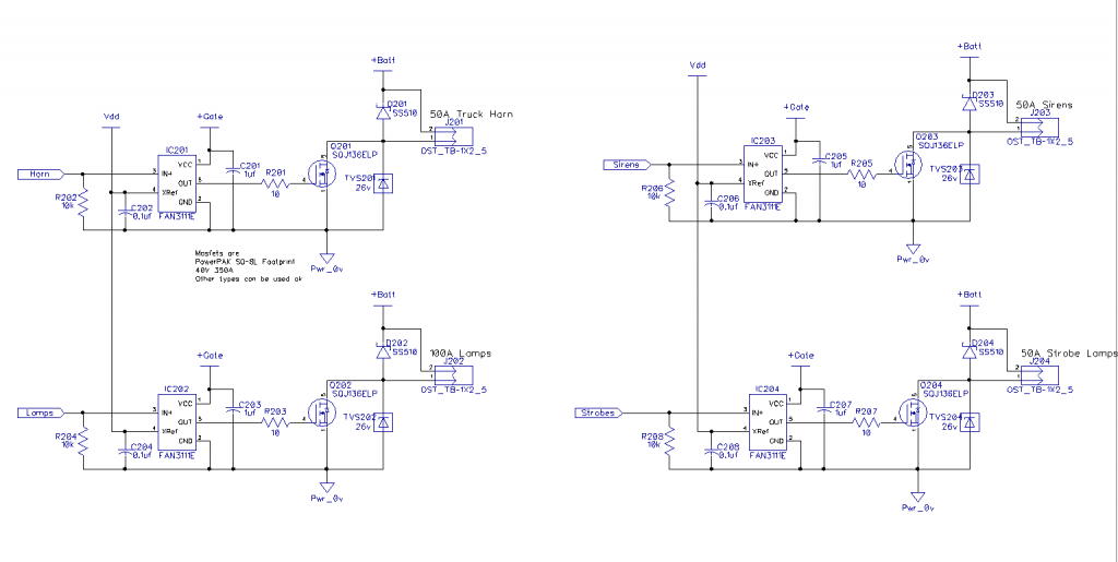 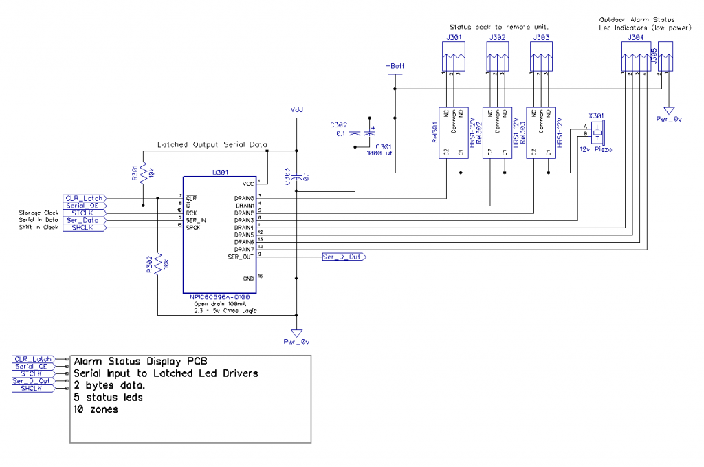 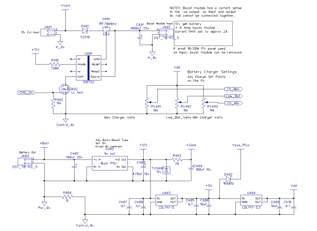 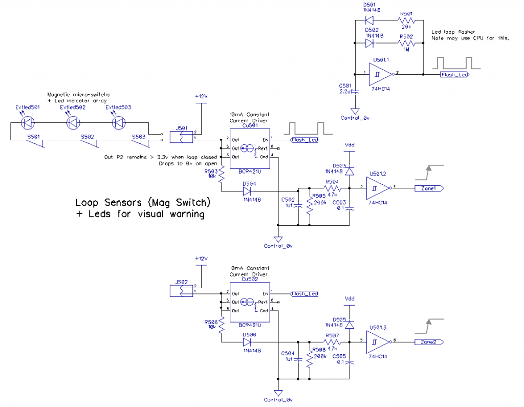 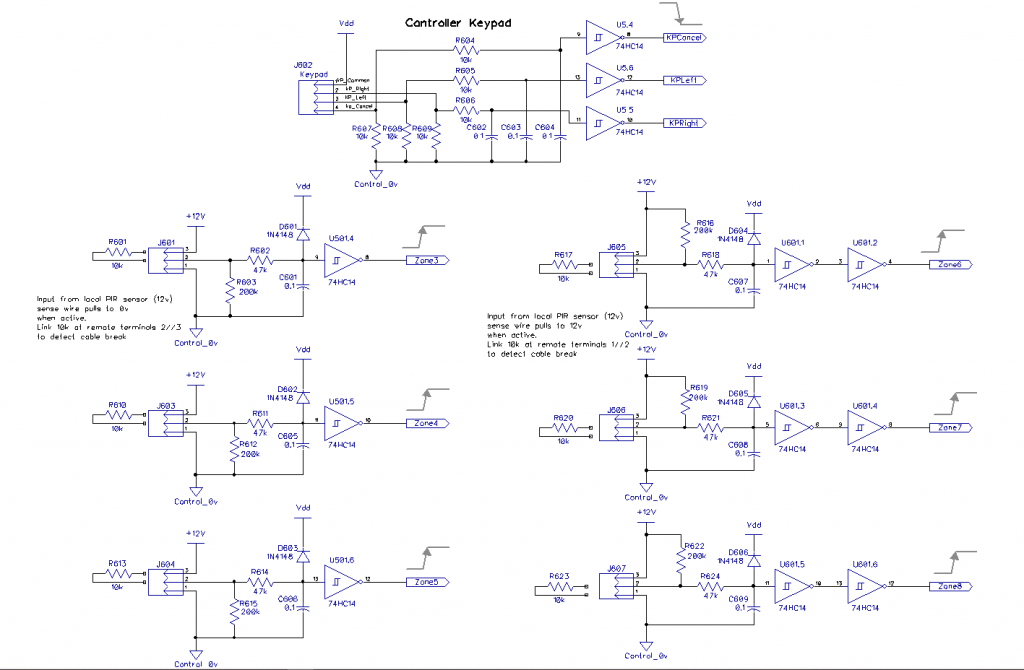 I will also use some of design ideas in the Pico H-Bridge driver module, then get on and do both PCB's; I do like the PI Pico, its an interesting cpu to play with, I just hope they bring out a revision to fix the broken interrupts and threading. Mike |
||||
| panky Guru Joined: 02/10/2012 Location: AustraliaPosts: 1127 |
Hi Mike, can you expand on your quote above please? What impact, if any, does this have on MMBasic on the Pico? Regards, Doug. ... almost all of the Maximites, the MicromMites, the MM Extremes, the ArmMites, the PicoMite and loving it! |
||||
| Solar Mike Guru Joined: 08/02/2015 Location: New ZealandPosts: 1211 |
I'm using micro-python here, so my comment is about those core libraries, not MMBasic. Edit: See Pico Forum Its really crap that the Pico board manufactures have released a product knowing it doesn't work fully, and don't appear to be doing anything about fixing the problems. Mike Edited 2021-08-12 13:04 by Solar Mike |
||||
lew247 Guru Joined: 23/12/2015 Location: United KingdomPosts: 1709 |
Board manufacturers at fault? Seems to be software Micro Pyton not working the way you want it and not the boards fault IF it's a security system you're building, why use a Pico? saving a tiny bit of money?~ Wouldn't be be much more prudent to use a decent cpu that can do the job that has a proven track record? Edited 2021-08-12 16:55 by lew247 |
||||
| Mixtel90 Guru Joined: 05/10/2019 Location: United KingdomPosts: 8904 |
The Pico board itself is barely more than the RP2040 pins wired out together with a dc/dc converter. There isn't much else, certainly nothing that effects interrupts or threading. The circuit is in the Pico Datasheet. Those are either on-chip problems or, far more likely, bad python libraries. Have you considered using Circuit Python rather than microPython? I think it's geared more towards I/O tasks. The Pico doesn't come with microPython - you have to add that to make it do anything at all so it seems rather unfair to blame the problems on the Pico. :) The RP2040 does have problems, but AFAIK those are mostly concerned with the ADC where there are some incorrect capacitor values. I haven't investigated further. The Pico would be a good platform for an addressable system, where inputs go into local nodes (or can stand alone) which are linked over a simple serial bus or even RF to cross buildings. Far less site wiring. The bus can be multi-voltage and/or encrypted to prevent tampering. That sort of scheme can even have multiple master panels. But I see I'm going off on a tangent again... I do that. :) Mick Zilog Inside! nascom.info for Nascom & Gemini Preliminary MMBasic docs & my PCB designs |
||||
| Solar Mike Guru Joined: 08/02/2015 Location: New ZealandPosts: 1211 |
@lew247, I didn't literally mean the physical board, more the Co. releasing the product + software combination; its the Pico micro-python core software that's at fault and lack of fix thereof; Not blaming the board design at all. Its early days for the product, no doubt there will be a fix at some stage. @Mixtel90, Circuit Python doesn't support the other core at all. Reason why I'm wanting to use this board is the advertised dual cpu usage, I'm used to commercial software programming in an object orientated dot net environment using multiple cores and complementary threading tasks, this board with all its release hype seemed a good candidate for experimentation in that aspect in a simple IO based controller, not so important in this security system but absolutely required in the other H-Bridge controller project, when using Python. Cheers Mike Edited 2021-08-12 19:13 by Solar Mike |
||||
| matherp Guru Joined: 11/12/2012 Location: United KingdomPosts: 11499 |
Neither micro-python nor Circuit Python are anything to do with the Raspberry Pi Foundation. Their "deliverable" is the H/W, the C SDK, and the various manuals. My experience is that once over various "learning" issues the SDK is pretty robust. IMHO the whole micro-python thing is an example of uncontrolled open source. It has to be pretty much impossible to support all the platforms that they are attempting with robust good quality and the Pico implementation seems to be an example of this. I know from my own experience how long it takes to port MMBasic to a new platform and how much scope there is for platform specific errors to creep in. Moral of the story is that if you want to code on the RP2040 then currently it is only using C where you can be reasonably confident things will work and where you can expect support from the RP2040 developers. |
||||
| Solar Mike Guru Joined: 08/02/2015 Location: New ZealandPosts: 1211 |
Seems a good time to practice my C then, very rusty I'm afraid, that's why I initially went with Python. Mike |
||||
| Solar Mike Guru Joined: 08/02/2015 Location: New ZealandPosts: 1211 |
Sticking with the PICO 2040 module, good excuse to update my very rusty C coding to use the second CPU if I want to use threading. Have made a few alterations to the final schematic, added more high power mosfet output switches for Horns, Strobes, Sirens and Lamps; these are coupled directly to the CPU with tiny mosfet drivers. All analog inputs are multiplexed by an analog mux chip, 74HC4051 with a common Low Pass active filter. Digital IO from the various types of zone sensors, 16 in all are connected via 74HC251D digital multiplexers. The IO stuff takes up a lot of space so have placed that on a separate plugin pcb and sits over the main pcb. The slower LED status display leds and output relays are accessed by power serial to parallel output chips NPIC6C596A, these can drive 100ma on each IO pin; the leds will be on a small pcb connected by ribbon cable so can bolt to the front panel of the case. Haven't started this board yet, next on the list. Main PCB 245 x 128mm: 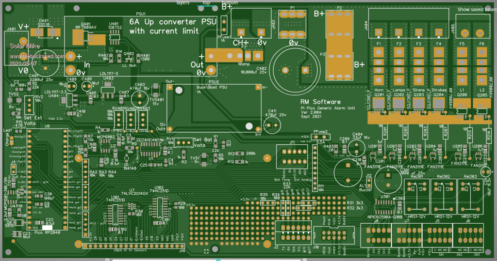 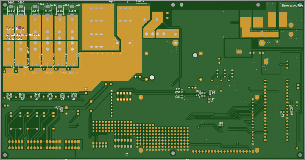 IO Zone Inputs 100 x 60mm: 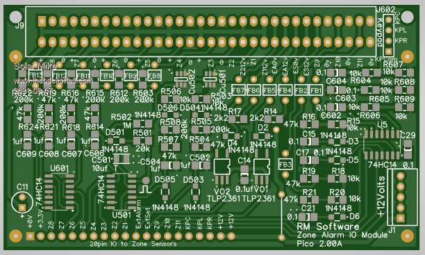 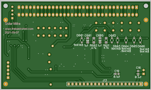 Cheers Mike |
||||
| Solar Mike Guru Joined: 08/02/2015 Location: New ZealandPosts: 1211 |
Schematic: PicoAlarm_2.pdf MIke |
||||
| Solar Mike Guru Joined: 08/02/2015 Location: New ZealandPosts: 1211 |
Schematic for the Led status display board, decided to use the serial input TLC5925 constant current Led drivers, so Led resistors are not required. Each zone will have 2 status Leds. 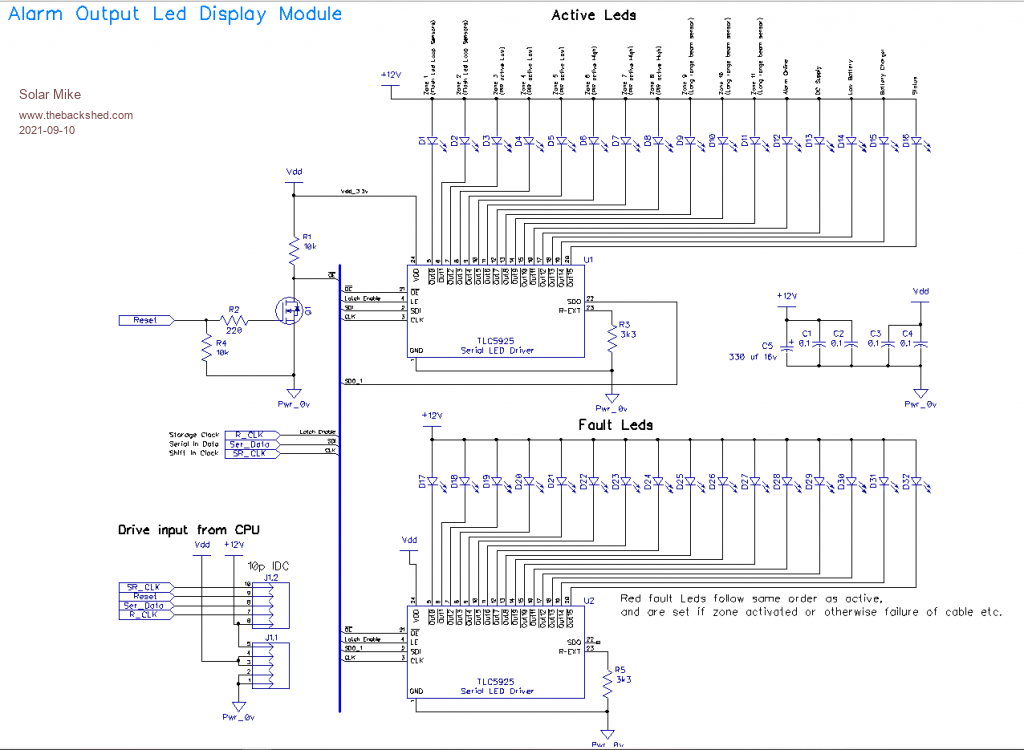 Mike |
||||
| Solar Mike Guru Joined: 08/02/2015 Location: New ZealandPosts: 1211 |
SPI serial Led display PCB, 100 x 65mm, smd or 3mm leds mount on the top half of the pcb, so they can show through holes or a slot cut in the front panel. 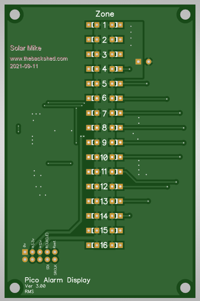 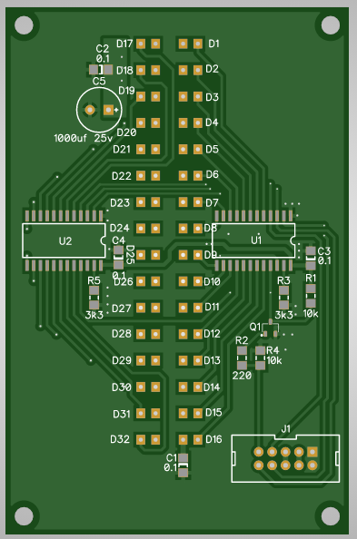 Cheers Mike Edited 2021-09-11 18:34 by Solar Mike |
||||
| Volhout Guru Joined: 05/03/2018 Location: NetherlandsPosts: 5930 |
Impressive job Solar Mike. The boards all look absolutely good. Please also post some pictures when they are assembled. About the power outputs. 50A - 100A are impressive currents, especially in the common path (all outputs loaded). Did you take special precaustions to prevent the PCB from overheating ? Is it 2 ounce copper ? or even thicker ? Volhout PicomiteVGA PETSCII ROBOTS |
||||
| Solar Mike Guru Joined: 08/02/2015 Location: New ZealandPosts: 1211 |
The underside of the pcb (1oz) current tracks has a tinned solder mask, so additional heavy gauge wire can be soldered on to augment the current capacity. Alarms are not running continuously and of limited duration, so not too worried about some short term heating. The mosfets have well in excess of 100 amp rating, so can switch very high peak currents, ie the truck horn requires > 40 amps on start. Will post the zipped up gerbers to anyone here who wants them, no doubt the pcb could be used for other generic purposes. Cheers Mike |
||||
| The Back Shed's forum code is written, and hosted, in Australia. | © JAQ Software 2026 |
