
|
|
Forum Index : Microcontroller and PC projects : Question: settick faster, or alternative
| Author | Message | ||||
| Volhout Guru Joined: 05/03/2018 Location: NetherlandsPosts: 5927 |
Maybe someone can point me in the right direction... I am looking at a problem, and for solving it I need a 3 phase sinewave (120 degrees between phases) at 50Hz or 60Hz. There are several ways to generate a 3 phase sinewave, in example. 1/ PWM (3 channels) and write sine values to them with 120 degrees pahse shift (i.e. prepared in an array). 2/ Parallel (write 16/32 bit data, similar the way video is build in a CMM(2) and use a resistor network to make it analog). This can either via the "port" command, or using SPI and external shift registers. 3/ Feed an audio stream that is pre-sampled repeatedly to the DAC. For 3 phase you would need 3 DAC's, but with external hardware (need opamps to buffer anyway) you can derive the 3'rd phase from the other 2. Of coarse this is also true for options 1/ and 2/. Option 3 can only work on a CMM(2). Not on an MX or maybe a Pico. It needs a pre-configured audio stream, and stitching the repeats seemlessly together may be difficult. If it where a single phase, you could create a sample that starts and ends at zero, so any delay would only cause phase shift. But when the other stereo channel is 120 degrees phase shifted, the distortion would be larger. Let's assume you would design around 128 samples per sine wave (at max 60Hz). That would mean an output update rate of 16.6ms/128 = 130us. In basic you would need a timer tick of 130us (Settick 0.13,doint). And in the interrupt routine you would only send the next vaue to either SPI, port, or PWM. When using PWM at 8 bit resolution, the PWM clock must run at 2MHz clock minimum. When using SPI, and sending data (24 bits) the SPI clock must be 130us/24 = 5us (200kHz. easy peasy, a 74HC164 runs at 24 MHz easily). When using the port command, you need stitch pins together for 16 bits, and mke sure these update simultanaous. That is probably the biggest risk. that some bits toggle later than others. (unless, a pico is used with the PIO sequencer, but then, how to make sure 16 or 24 bits are updated with the right data. Each channel can only do 5 bits parallel). Anyway: PWM or SPI, you need an interrupt in the basic program every 130us. And the fastest tick is 1ms. I am open to suggestions. As additional info I can only explain that the thing needs do nothing else. Only generate 3 phase sine wave, maybe only a switch at a GPIO pin to toggle between 50 and 60Hz. I hope someone has an idea how to do this. Volhout. P.S. Yes there are DDS, but 3 phase DDS needs hardware design, P.P.S. I am almost tempted to take a binary counter, and put a sinewave table in 3 parallel EPROM's. That is a hardware solution, that is guaranteed to work. PicomiteVGA PETSCII ROBOTS |
||||
| Mixtel90 Guru Joined: 05/10/2019 Location: United KingdomPosts: 8904 |
PWM is almost certainly the simplest. I do have a soft spot for option 2 though as it appeals to the experimenter in me! You can have more than 8-bit resolution. One of the nice things is that all pins are driven either high or low so there is no interaction between the three phase generation. The hardest bit is getting the binary weighted resistors. I once did a similar thing but only single phase. I drove a crude amplifier into the 12+12v secondaries of a transforner and took the mains side out. We needed a 120/240v variable frequency supply for testing synchroscopes and auto-synch equipment at the time. :) How accurate do you need to be? Would a simple timing loop be better than an interrupt? Edited 2021-08-18 04:37 by Mixtel90 Mick Zilog Inside! nascom.info for Nascom & Gemini Preliminary MMBasic docs & my PCB designs |
||||
| Volhout Guru Joined: 05/03/2018 Location: NetherlandsPosts: 5927 |
Hi Mixtel90, Can you share your latest PIO assembler and instructions, I think maybe PIO can do it, looking at this video (Based on micropython). In EP.2 of the video they explain however that feeding new data is done from the python program. And that is slow(er). PIO for parallel output I simply have not been playing with the PIO lately. So I have to re-educate myself how to do this... Regards, Volhout Edited 2021-08-18 04:51 by Volhout PicomiteVGA PETSCII ROBOTS |
||||
| Mixtel90 Guru Joined: 05/10/2019 Location: United KingdomPosts: 8904 |
No problem - but remember that I'm barely scratching the surface of understanding the PIO. Writing an assembler for it and actually being able to use it aren't the same thing. lol PASM12a.zip PicoMite TINAM doc 0817.zip I think the PIO can output a value to PWM... EDIT: OOH! I've just been looking at the Picoputer project on youtube. He's programmed the PIOs to give 4 serial ports (data_in and data_out on each). Then he's running a Transputer emulator on the Pico. Effectively a Transputer on a Pico. He thinks he may be able to put an emulator on each core, with some of the data links internal, to get a 2 Transputer package. He got the basic single Transputer setup to run with a test rig then swapped it out for a real Transputer and the result was identical, so it seems to be viable. Edited 2021-08-18 06:53 by Mixtel90 Mick Zilog Inside! nascom.info for Nascom & Gemini Preliminary MMBasic docs & my PCB designs |
||||
| Tinine Guru Joined: 30/03/2016 Location: United KingdomPosts: 1646 |
Why not simply use a Parallax Propeller? It can do this stuff in its sleep and programmable in BASIC or C or Forth or PASM (propeller assembly) Perfect companion for the micromite. |
||||
| phil99 Guru Joined: 11/02/2018 Location: AustraliaPosts: 3289 |
Since you are using a single frequency and op amp buffers you can send a single sinewave to the first op amp and use an RC phase shifter to the next, and same again for the third. Choose RC values to get 60 degrees, with the op amp inverting (+180 deg.) giving +240 = -120, +240 again = +120. Did this many decades ago with a phase shift oscillator as the source. |
||||
| vegipete Guru Joined: 29/01/2013 Location: CanadaPosts: 1179 |
If the output frequency is fixed, why bother with a DAC at all? A balanced square wave into a resonant circuit would generate a nice sine wave. Yes, it must be tuned for the required output frequency, but if that is stable, all is good. Visit Vegipete's *Mite Library for cool programs. |
||||
| Volhout Guru Joined: 05/03/2018 Location: NetherlandsPosts: 5927 |
I have a quick solution in using the PORT command. On the pico, using GP0..5 for phase 1, GP6..11 for phase 2, GP12..17 for phase 3 3x 6bit DAC's with resistors, and low pass filter cap to terminate (remove the DAC steps somewhat). The resistor DAC is particular accurate (1.1k, 2.2k, 4.3k, 9.1k, 18k, 36k), the filter caps are 1uF. I create an array with sine, and sine shifted values. An in a single PORT command I write the 18bits (3x6bits) to the IO pins. Currently the program relies on the MMBasic interpreter execution speed (so any new compile may result in re-tuning). The output frequency (50Hz) is determined by the length of the array with samples. More data = lower frequency. With default speed (125MHz) 210 samples result in 50Hz. No need to align the number of samples with a multiple of 3 (as a HW guy would do, to make exactly 120 degrees shift possible) since the sine values in the table are phase shifted with "float" accuracy...hihi. 'test port command: generate 3 phase 50Hz 'defines samples = 210 'tuner to achieve 20ms (50Hz) ' = 3 * Int(samples / 3) 'make 120 degrees 3 phase, multiple of 3 bits = 6 resol = 2^(bits-1) Print "resolution = ";resol*2;" using ";samples;" samples per loop" 'init setport setsine 'loop Do 'Timer = 0 For i%=1 To samples Port(gp0,18) = a%(i%) Next i% Loop 'x=Timer Print "loop time = ";x;" ms" End Sub setport SetPin gp0,dout SetPin gp1,dout SetPin gp2,dout SetPin gp3,dout SetPin gp4,dout SetPin gp5,dout SetPin gp6,dout SetPin gp7,dout SetPin gp8,dout SetPin gp9,dout SetPin gp10,dout SetPin gp11,dout SetPin gp12,dout SetPin gp13,dout SetPin gp14,dout SetPin gp15,dout SetPin gp16,dout SetPin gp17,dout End Sub Sub setsine Dim a%(samples) 'L1 For i%=1 To samples a%(i%)=Int(resol*(1+Sin(i%*(2*Pi/samples)))) Next i% 'L2 For i%=1 To samples a%(i%)=a%(i%)+ 2*resol*Int(resol*(1+Sin(2*Pi/3 + i%*(2*Pi/samples)))) Next i% 'L3 For i%=1 To samples a%(i%)=a%(i%)+ (2*resol)*(2*resol)*Int(resol*(1+Sin(4*Pi/3 + i%*(2*Pi/samples)))) Next i% End Sub The test circuit: 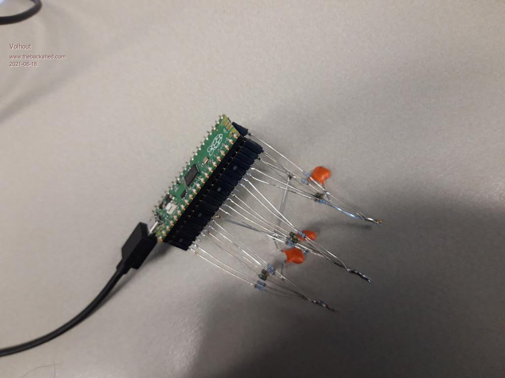 The output signals measured with a 4 channel oscilloscope. 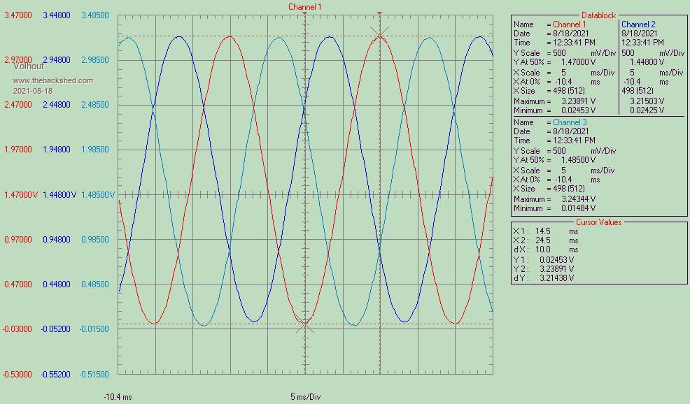 Some may wonder why I did not use the PIO to do exactly this ? Well, as far as I understood from the documentation, the PIO will output the data to the pins, but then needs new data in it's output shift register. That new data must be provided by the ARM. In our case, MMBasic. I have not been able to fidn out if the PIO can use some kind of DMA to read a basic array in a circular way autonomously. If MMBasic needs to provide the data to the PIO, why not send it to the port directly ? Edited 2021-08-18 21:12 by Volhout PicomiteVGA PETSCII ROBOTS |
||||
| Volhout Guru Joined: 05/03/2018 Location: NetherlandsPosts: 5927 |
Hi Tinine, Yep, though about that. But I needed somethin with parts I have in my shed. And I do not have Propeller, not it's development environment. Honestly, if this would not have worked, I would have tried a Arduino, programmed in C. It has a fast interrupt, and when using the analog pins as digital out, and UNO has 18 I/O that can be used the same way (A0..A5 and D2...D13). Remains is fiddling out how to map the data. Regards, Volhout PicomiteVGA PETSCII ROBOTS |
||||
| Mixtel90 Guru Joined: 05/10/2019 Location: United KingdomPosts: 8904 |
I like that. It's got bits hanging in mid air, just as they should. :) It seems to be working fine. If you can prove it at 60Hz it might be worth trying to get some closer resistors if you need less distortion. Mick Zilog Inside! nascom.info for Nascom & Gemini Preliminary MMBasic docs & my PCB designs |
||||
| Volhout Guru Joined: 05/03/2018 Location: NetherlandsPosts: 5927 |
Here the same code, running on a ATMEGA328 (Arduino nano), in C. This does not rely on execution speed of the language, but uses timed interrupts. There is jitter (interrupt response time) of 6us. The difference with the MMBasic pico is that the Arduino nano outputs 5V sine wave, the pi pico 3.3v. I made this since I have only 1 pi pico, and a sh*tload of nano's (from the time they cost near to nothing). // 3 phase generator // This is a 50Hz 3 phase (L1/L2/L3) generator running on ATMEGA328 // Outputs are 3x 6 bit ports, that need an external DAC (resistor network). // In prototype setup 36k, 18k, 9.1k, (2.7+1.8)k, 2.2k, 1.1k where used with 1uF filter cap. // Each sine wave consists of 128 samples. // Uses a Timer 1 interrupt to output samples. #include <TimerOne.h> const int samples = 128; // samples per sine const int resolution = 31; // 6 bit resolution (5 bit and sine aplitude is +/- 1) int delay_tmp = (20000/samples); // 50Hz = 20ms = 20000us int Count; byte L1[samples], L2[samples], L3[samples]; void setup() { // set IO pins: DDRD = DDRD | B11111100; // for L3 set port D2...D7 output = pin 2..7 DDRB = DDRB | B00111111; // for L2 set port B0...B5 output = pin 8..13 DDRC = DDRC | B00111111; // for L1 set port C0...C5 output = pin A0..A5 // generate data arrays for sine samples for (Count = 0; Count < samples; Count++) { L1[Count] = (byte) resolution * (1 + sin(2*PI*Count/samples)); L2[Count] = (byte) resolution * (1 + sin((2*PI*Count/samples) + 2*PI/3)); L3[Count] = (byte) resolution * (1 + sin((2*PI*Count/samples) - 2*PI/3)); } /* // for debug Serial.begin(9600); for (Count = 0; Count < samples; Count++) { Serial.print(L1[Count],L2[Count],L3[Count],"\r"); delay(10); } */ Timer1.initialize(delay_tmp); //set Timer 1 for 156uS interrupts (@128 samples) Timer1.attachInterrupt( T1_ISR ); // start interrupt } void loop() { // do nothing } void T1_ISR() { // send new samples out PORTC = L1[Count]; PORTB = L2[Count]; PORTD = (PIND & 0x03) + (L3[Count] << 2); // prepare for next samples Count++; Count = Count & (samples-1); } PicomiteVGA PETSCII ROBOTS |
||||
| Mixtel90 Guru Joined: 05/10/2019 Location: United KingdomPosts: 8904 |
All foreign to me. I never could get the hang of that horrible arduino language. :) Mick Zilog Inside! nascom.info for Nascom & Gemini Preliminary MMBasic docs & my PCB designs |
||||
| led-bloon Senior Member Joined: 21/12/2014 Location: AustraliaPosts: 209 |
Here is some code to generate 50/60Hz O/P on three pins of the pico using PIO. Some filtering may just get you some reasonable 3 phase sinusoidal O/Ps. May be of some use? ' PIO program that can output 50/60Hz squarewave on GP0-2 (3 pins > 3 phases) Option Explicit DIM integer asmblock(7) VAR RESTORE ' Retrieve PIO code into asmblock() ' Preparations : reserve GP0-2 for PIO SetPin 1,pio0 SetPin 2,pio0 ' Pin 3 Gnd SetPin 4,pio0 PIO clear 0 PIO PROGRAM 0,asmblock() ' Set clock 5kHz for 50Hz on pio0 sequencer 0 ' or change frequency to 6kHz for 60Hz ' Assign 3 pins to SET group and assign a base of 0. PIO init machine 0,0,5000,pio(pinctrl 0,3,0,0,0,0) ' Start the output PIO start 0,0 PIO execute 0,0,0 Do Print "."; ' do something to show we are working... Pause 1000 Loop ---------------------------- PIO Assembler: Data "set pindirs 7" Data "set pins 5 [16]" ' Pins 1 & 4 Data "set pins 1 [15]" ' Pin 1 Data "set pins 3 [16]" ' Pins 1 & 2 Data "set pins 2 [15]" ' Pin 2 Data "set pins 6 [16]" ' Pins 2 & 4 Data "set pins 4 [15]" ' Pin 4 Data "jmp 1" Data "" ' Data contained in asmblock() ' and VAR SAVEd by the assembler program &HF003EF01F005E087 &H0001EF04F006EF02 6 @ &HA042A042A042A042 nops ---------------------------- led Edited 2021-08-20 16:37 by led-bloon Miss you George |
||||
| Volhout Guru Joined: 05/03/2018 Location: NetherlandsPosts: 5927 |
Hi led-bloon, Thank you for creating this. Interesting to see how you solved the divide by 100 (by delays (16+1),(15+1),(16+1),(15+1),(16+1),(15+1),1). The "1" is the instruction itself, that last "1" is the jump. This is a small asymmetry. If you set the frequency to 99x50Hz (4950) then the jump can be replaced by a .wrap The thing I do not understand yet, is how to get data generated by the basic program to the output (shift) register in a way that avoids basic interference. I used the "pull". But I wonder if the X and Y registers can be used for an offset (like in 6502, X and Y can be used as index registers) and pull next value (32 bit shift register) from memory. So we have to "manipulate" in basic so a data array of 64 bit integers hold 2x 32bit values in each cell, but then the PIO can do autonomous pulls of data). PicomiteVGA PETSCII ROBOTS |
||||
| Mixtel90 Guru Joined: 05/10/2019 Location: United KingdomPosts: 8904 |
What a nicely laid out program, led. Even I can follow (some of) that. :) .wrap makes the program counter think it's reached the end of program memory so it just rolls over to .wrap_target (or whatever it's called...). As .wrap occurs during the instruction read rather than execute it doesn't take up a clock cycle so it effectively happens in zero time, whereas jmp needs a clock cycle. .wrap lets you generate truly square waves (and the RP2040 I/O ports have very fast rise/fall times, hence the number of GND pins - they aren't just being nice to those who lay out PCBs. The Pico PCB was designed at the same time as the RP2040 so it is actually pretty much ideal for it.). Edited 2021-08-20 17:26 by Mixtel90 Mick Zilog Inside! nascom.info for Nascom & Gemini Preliminary MMBasic docs & my PCB designs |
||||
| led-bloon Senior Member Joined: 21/12/2014 Location: AustraliaPosts: 209 |
@Volhout Checking .wrap stuff now, making sure I fully understand it. Will then move on to shift registers. The X & Y registers AFAIK are only temp hold registers for data, period. You can move data in/out to pins, Y reg, Shift reg, or just use as a counter. But don't take my word for it! Will keep going while having fun. led Edited 2021-08-20 17:53 by led-bloon Miss you George |
||||
| Volhout Guru Joined: 05/03/2018 Location: NetherlandsPosts: 5927 |
OK, the final version.... (for arduino nano). The interrupt latency is bypassed by using the same timer, with the same settings, but polling of the timer overflow bit. The jitter is less than 1us. // 3 phase generator // This is a 50Hz 3 phase (L1/L2/L3) generator running on ATMEGA328 // Outputs are 3x 6 bit ports, that need an external DAC (resistor network). // In prototype setup 36k, 18k, 9.1k, (2.7+1.8)k, 2.2k, 1.1k where used with 1uF filter cap. // Each sine wave consists of 128 samples. // Uses a Timer 1 polled for most accurate timing. const int samples = 128; // samples per sine const int resolution = 31; // 6 bit resolution (5 bit and sine aplitude is +/- 1) int delay_tmp = (20000/samples); // 50Hz = 20ms = 20000us int Count; byte L1[samples], L2[samples], L3[samples]; void setup() { // set IO pins: DDRD = DDRD | B11111100; // for L3 set port D2...D7 output = pin 2..7 DDRB = DDRB | B00111111; // for L2 set port B0...B5 output = pin 8..13 DDRC = DDRC | B00111111; // for L1 set port C0...C5 output = pin A0..A5 // generate data arrays for sine samples for (Count = 0; Count < samples; Count++) { L1[Count] = (byte) resolution * (1 + sin(2*PI*Count/samples)); L2[Count] = (byte) resolution * (1 + sin((2*PI*Count/samples) + 2*PI/3)); L3[Count] = (byte) resolution * (1 + sin((2*PI*Count/samples) - 2*PI/3)); } /* // for debug Serial.begin(9600); for (Count = 0; Count < samples; Count++) { Serial.print(L1[Count],L2[Count],L3[Count],"\r"); delay(10); } */ // stop all interrupts noInterrupts(); // initialize timer 1 in phase correct PWM mode at 0.5us tick, due to symetry this is 1us ICR1 = delay_tmp; // set TOP to delay_tmp TCCR1A = 0x00; // Timer1 Control Reg A: Normal port operation, Wave Gen Mode normal TCCR1B = _BV(WGM13); // set mode 8: phase and frequency correct pwm, stop the timer TCNT1 = 0; // Reset Timer Count to 0 TCCR1B |= (1 << CS11); // 8 prescale } void loop() { // in fastest possible loop check timer 1 reach bottom while (!(TIFR1 & _BV(TOV1))) { }; TIFR1 |= _BV(TOV1); // clear TOV1 by writing 1 to it // send new samples out PORTC = L1[Count]; PORTB = L2[Count]; //PORTB = (PINB ^ B00111111); // debug at D13 for phase jitter PORTD = (PIND & 0x03) + (L3[Count] << 2); // prepare for next samples Count++; Count = Count & (samples-1); } PicomiteVGA PETSCII ROBOTS |
||||
| The Back Shed's forum code is written, and hosted, in Australia. | © JAQ Software 2026 |
